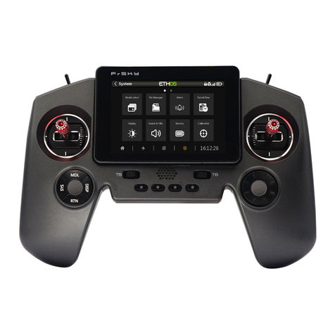
Fly-Dream V3 User manual

2.4 GHz Radio Control System
www.fd‐rc.com
Version:V3.1
Update:V3.1

ThankyouforpurchasingourFly‐Dream2.4GHzV3RadioControlSystem.
Wearesureyouwillenjoyit.Thefollowingnoteswillguideyouthrough
thesimplesetupprocedures.Modelisnottoy,wegiveyouastrong
reminder that you should reading the contents of this article carefully
beforeusingit,whichistheinterestsofpublicsafetyconsiderations
Attention:
1. Please use this in the provided venues, juveniles are asked to be accompanied by a
guardian to use.
2. Any electronic may lose control, please set up failsafe correctly to avoid or reduce
losses.
3. Range is affected by the environment .Please test range in the open away from
any obstacles.
4. As a result of receiver sensitivity's enhancement, will cause certain jamming
situation between some receivers and the transmitters (on usual,the distance between
receiver and transmitter is3cm). This does not affect the normal use.
5. Because IS-4R0 is a ultra light receiver , the bind is not the same as others, please
read the manul of “Bind receivers"
6. Once bind success,use for ever and never bind again!
7. Please note the positive and negative charges on the voltage protector, don't
make mistake
8. Do not fly unless it is safe to do so. Consider the safety of others at all times when
flying.
FD 2.4GHz V3 radio control system
FD 2.4GHz works with the standard of Frequency-Hopping Spread Spectrum
(FHSS), it changes frequency quickly throughout the 2.4 GHz band, utilizing 19
separate frequencies in order to reduce interference from other unwanted signals.
This ensures safe, stable operation over a wide range of conditions likely to be
encountered at any flying field.
FD 2.4GHz V3 radio control system's features
◆Long range and more Stability
◆More small and more ultra light
◆Failsafe. You can set the receiver to default to a pre-set position on all channels in
the unlikely event of signal loss.
◆Automatic frequency scan when turning on the transmitter and receiver ensures no
frequency clash and maximum safety.
◆Bind once, use forever!
◆Range test. Convenient method to check the performance of the system which
means you won't need to walk kilometers away.
◆Ultra-low-power design. Low power consumption by Transmitter modules and
Receivers.

FD 2.4GHz V3 radio control system's details
1.FD2.4GHzV3radiocontrolsystemconsistsof:
Transmittermodule(IS‐8F/IS‐8J)×1
Receiver(IS‐8R/IS‐6R/IS‐4R/IS‐4R0)×1
Transmitterantenna(IS‐TA)×1
Voltage protector×1
2.Transmittermodulecompatibility
Futabamodule(IS‐8F):
Futaba:3PM/3PK/7U/8U/8J/9C/9Z/10CandFNseries.
Hitec:Optic6/Eclipse7.
WFLY:WFT08/WFT09.
JRmodule(IS‐8J):
JR:347/388/783/U8/PCM10/PCM10S/PCM10SX/PCM10IIS/
8103/3810/J9303/MX‐22/MX‐24S/PX/9X/9XII/Turnigy9X/11X
3.Transmittermodulespecifications
Dimensions:58.5×37.5×22.1mm(IS‐8F)
63.9×48.5×36.5mm(IS‐8J)
40.2×20.1×7.2mm(IS‐8D)(DIYkit)
OperatingVoltage:6V~18V
OperatingCurrent:40mA
OutputPower:<19mW
Resolution:1μs
4.Receiverspecifications:
TypeIS‐4R0(4CH)IS‐4R(4CH)IS‐6R(6CH)IS‐8R(8CH)
Size(mm)17×13.7×4.524×15.1×5.634.2×18.4×8.736.2×20.1×8.1
Weight1g2.2g6.5g7.3g
Distance300m
(onground)
450m
(onground)1200m1200m
Operating
Voltage3.7V~6.0V3.7V~6.0V4.8V~6.0V4.8V~6.0V

Follow these easy steps to set up your transmitter and receiver.
Install the transmitter module and receiver
1.Removetheoriginaltransmittermodule.
2.PuttheFD2.4GHztransmittermoduleintothemoduleportand
screwonthetransmitterantenna.
3.Whenyoudoinstallthereceiverinthemodeltrytoplacethetipof
theantenna(thesilverbit(s)approx33mmlong)awayfromobjectswith
highconductivity,suchasmetalparts,servos,ESCʹs,batterypacks,
wires,andcarbonfiberstructures.Forreceiverswith2antennasposition
thetipsoftheantennassotheyareapproximately90degtoeachother.
Ifpossibleputthetipoftheantennas(the33mmlongsilverbit)outside
ofthefuselageformaximumreception.
Bind and set Failsafe on the receiver(s)
Beforeinstallingthereceiver(s)inyourmodel(s)followtheinstructions
belowtobindthereceivertothetransmitter.
Bind receivers
1.Turnthetransmitteron.MakesurethatyourtransmitterissettoPPM
mode,andthenturnthetransmitteroff.Note:‐Receiverswillnotbindif
thetransmitterissettoPCMmode.
2.Pressthe“BIND”buttonontheTXmoduleandturnonthe
transmitter.TheLEDonthemodulewilllightredandgreenfor0.5s
thengoofffor1s.Releasethebuttonwithinthis1s.TheLEDonthe
modulewillflashbetweenredandgreenwhenitgetsintobindmode.
3.ThebindingprocedureisdifferentforIS-4R0 (see 3A) and IS-4R, IS-6R
and IS-8R (see 3B)
3A:IS‐4R03B:IS‐4R&IS‐6R&IS‐8R
Afterthemodulegetsinto
bindmode,thenconnectthe
receivertobattery,theLed
onreceiverwilllightonce,
thenflashquicklyandthen
putoff,thisshowsthe
moduleandreceiverbind
successful,nowturnoffthe
powerofreceiverandturn
offthetransmitter.
Pressandholdthebuttononthe
receiver.Connectthereceivertothe
battery.TheLEDonthereceiverwill
lightImmediately(whiletheLEDison)
releasethereceiverbutton.TheLED
willflashquicklyseveraltimesandgo
out.Turnoffthepowertothereceiver.
Ifyoudonotwanttobindmore
receiversatthistime,turnoffthe
transmitter.

4.Checksystemoperation.
Turnthetransmitteron.ThemoduleLEDshouldbegreen.Connectthe
receivertothebattery.TheredLEDonthereceiverwillflashthreetimes
(nowitissearchingforthefrequency)andlightred,indicatingthe
receiverisoperatingproperly.TheLEDonthereceiverwillnotlight
whenthereisnosignal.
OncethesuccessfulbindingofTxmoduleandReceiver,nobinding
againinthefollowinguse.

Set Failsafe
IS‐4R0
IS‐4R0cansetfailsafeautomaticly,whenitlosecontrol,allchannelswith
nooutput.
IS‐4R&IS‐6R&IS‐8R
1.Afterinitialbinding,turnonthetransmitter.
2.Pressandholdthebuttononthereceiver.Connectthereceivertothe
battery.TheLEDonthereceiverwilllight(about1s)andthengoout
(forabout1s).Atthistime(whentheLEDoff)removeyourhandfrom
thereceiverbutton.TheLEDonthereceiverwillthengoon.
3.Movethejoystickonyourtransmittertowhereyouwantthesurfaces
/motoretctobeintheeventoflostsignal.Pressthebuttononthe
receiver.TheLEDwillflashseveraltimes;thisshowsthereceiverhas
rememberedthepositionwhichyouhaveset.Intherareeventthatyour
systemlossessignal,allchannelswillreturntothepositionwhichyou
haveset.
4.Turnoffthepowertothereceiver.Failsafeisnowset.
5.Checkthatfailsafeworks,byturningonthetransmitterthenthe
receiver/model.Turnoffthetransmitter.Thecontrolsshouldgototheir
presetposition.Theywillreturntothoseonthetransmitterwhenpower
isrestored.
6.GoFly.

Range checking
For safety, we suggest you conduct a range test before each flying session.
1).Haveafriendholdthemodelforyou.Positionthemodelatleasttwo
feet(60cm)abovenon‐metalcontaminatedground.Ifyoudon’thave
anyonetohelpyou,usesomethinglikeawoodenbench.Makesurethe
modelcannotmoveunderitsownpower.
2).Pressandholdonthe“RANGE”buttononthemoduleandturnon
thetransmitter. (pleasedon’treleasethebuttonforthewhole
process).ThereadLEDwilllightfor0.5sthentheyellowLEDlight,
thisshowsthemoduleisnowin“RANGE”mode.
3).Movejoysticksinthetransmitterandverifythatthemodelis
respondingnormally.Moveawaythetransmitterfromthemodelupto
10m(IS6R,IS8R)or8m(IS4R)or4m(IS‐4R0).Ifthecontrolsurfaces
moveasexpecteditshowstheTxmoduleandreceiverareworkingas
expectedandcanbeused.Ifcontrolislost,orthemodelbehaves
abnormally,pleasecheckandresolveanyproblemsbeforeconducting
anotherrangetest.Donotflyiftherangetestfailsandcannotbefixed.
4).Whenrangetestingiscompleted,releasethebutton.TheLEDonthe
Txmodulewilllightgreen,indicatingthattheTxmodulehasreturned
toitsnormalpowerstate.Youcannowfly.
DuringtherangetesttheTransmittermodulewillhavearangeof
approx10m(IS6R,IS8R)and8m(IS4R).Innormalpowermode,range
isgreaterthan1,200meters(IS6RandIS8R)and1000meters(IS4R)in
thesky.
Note:
1.OncetheTransmittermoduleandReceiveraresuccessfullybound,
thereisnoneedtobindagainifyouaddextrareceivers.
2.NotflywhenyouatRangeTestMode.
3.Intheextremelyrareevent(1inapproximately13million)that
anotherFly‐DreamsystemusesthesameIDitispossibletoresetthe
IDbypressingboth“BIND”and“RANGE”buttonstogether.(NOT
dothisunlessyouwanttoresettheID.Thereisabsolutelynoneedto
dothisinnormaloperations.)

Attach: Instruction of LED on the TX module
GreenLEDlighton Normalworking
YellowLEDstayon Shortrangetesting
LEDflashbetweenredandgreenBindcode
FlashredLEDChangeTXmoduleID
condition
Enjoy your Fly-Dream 2.4GHz
Radio Control System.
Ifyouhaveanyquestionspleasedonothesitatetocontactusorvisitour
website:www.fd‐rc.com
Orcontactwithyourlocalsupplier:
This manual suits for next models
2
Table of contents
