FLYDOR Unika User manual

Unika
Product Guide
KEEP FLIES OUT!


UNIKA RETRACTABLE SCREEN
The Unika Retractable Screen benefits from a compact cassette and profiles manufactured in
Extruded Powder Coated Aluminium. The screen mesh neatly retracts from view makin this
screen discreet. Window and door applications available, desi ned for domestic use. Face or
reveal fitted internally or externally.
The Unika Window (MUV) (MUV-BV) is unobtrusive with its
slimline rounded 36mm cassette. The spring tensioned
screen simply pulls down and securely locks into the
concealed side channel catches. An optional soft close brake
can be fitted to slow the screen retraction if desired. Simple
intermediate stops can also be fitted to allow the screen to be
held in two positions, ideal for top and bottom opening
windows. ow available in long drops when using the Better
Vue mesh option.
Offers excellent visability, air flow qualities and insect
protection.
Window models available:
MUV- Standard (18x16) Mesh
MUV-BV – Better Vue Mesh.
The Unika Door (MUH) (MUH- ) is available in both single
and double options . Ideal for use with existing French
doors, simple to install and easy to maintain. Soft close
brakes are fitted as standard to all our door models. Strong
magnetic strip closure. Offers excellent visability , air flow
qualities and insect protection.
Door models available:
MUH – Horizontal single door
MUH- – Horizontal double door.
All Unika models are fitted with our Standard Fibre lass
(18x16) Charcoal Mesh. Better Vue mesh is only available
for the Window versions (MUV-BV) .
1
White or Brown finishes as standard. Special option RAL colours are available.
Please contact our Sales Team for further details.

Unika Model Codes and Specifications.
Product Code Standard Specifications Options (POR)
Unika Door
Sin le
Rec Max Size
W = 1000mm
H= 2100mm
Double
Rec Max Size
W = 1600mm
H= 2100mm
MUH
MUH-
•Single (36 x 43mm) Slimline Rounded Extruded Powder
Coated Aluminium Cassette.
•Spring tensioned Fibreglass (18x16) Charcoal Mesh .
•Powder Coated Aluminium 30mm top and bottom channels.
•Full height Powder Coated Aluminium magnet side channel
closure.
•Front and back surface mounted rigid PVC handles. (x 2).
•Soft close brake.
•Face fitting and recess brackets. Allow 15 mm for face fittin
brackets, and 5mm for recess brackets.
•7mm PVC Cover Caps
•As above with Double (36 x 43mm) Slimline Rounded
Extruded Powder Coated Aluminium Cassettes.
•Surface mounted PVC sliding shoot bolts to one door.
•Anti Wind Pile.
•Re-inforced bar
handle profile.
•RAL colours .
Unika
Window
Rec Max Size
W = 1200mm
H= 1200mm
BV
SLS
MUV
MUV-BV
MUV-SLS
•Slimline (36 x 43mm) Rounded Extruded Powder Coated
Aluminium Cassette.
•Spring tensioned Fibreglass (18x16) Charcoal Mesh .
•Powder Coated Aluminium 30mm side channels.
•Front surface mounted rigid PVC handles. (x 2).
•Pull cord.
•Concealed catches.
•Face fitting and recess brackets. Allow 15 mm for face fittin
brackets, and 5mm for recess brackets.
•7mm PVC Cover Caps
•As MUV with Better Vue Long Drop Mesh (Max 2400mm)
•As MUV with Spring Loaded Locking Handle System. (SLS)
•Anti Wind Pile.
•Soft close
brake.
•Re-inforced bar
profile handle.
•Intermediate
stops.
•RAL colours .
2

Recess Fitting Width
If using the cassette fixing “m”
clips allow 5mm for fitting.
Tip – If the inner handle(s) on
the screen is catching the door
frame, the top and bottom
guides can easily be cut down
on site to reduce the width
accordingly.
Height Measurement (All types)
The height is from the top edge
to bottom edge of the cassette.
Tip - This measurement is
critical! Watch out for plinths
and any lips which are common
with UPVC doors. Allow
yourself at least 5mm if fitting
into a recess.
WIDTH
HEIGHT
5 mm
mm
43 mm
36 mm
Unika Profile(Not to scale)
mm
30 mm
Cassette
Door Frame
Opening Door
SCREEN SIZE
(Birds eye view illustrated - Minimum width shown, side uide and cassette can be positioned to suit).
15 mm
Mag Closure Channel
Single Door (Face Fitting)
Opening French Doors
SCREEN SIZE
(Birds eye view illustrated - Minimum width shown, cassettes can be positioned to suit).
15 mm
Double Door (Face Fitting)
15 mm
Measuring Guide. Unika Door.
Please take note before you measure;
Screens are manufactured to SCREEN SIZE (ed e of frame to ed e of frame excludin fittin s). FLYDOR do not make any
adjustments or allowances. All Measurements are in mm. Sizes to be supplied as Width x Hei ht.
3
Door Frame
Door Frame
Door Frame
Cassette
Cassette

Side Guide Channel
Window Frame
Window Opening Vent
SCREEN SIZE
(Birds eye view illustrated - Minimum width shown, side uides can be positioned to suit).
5 mm
15 mm
SCREEN SIZE
40 mm
Face Fittin without sill.
SCREEN SIZE
Recess Fittin with or
without sill.
15 mm
SCREEN SIZE
Face Fittin with sill.
WIDTH
HEIGHT Face Fixing L racket Recess Fixing M Clip
5 mm
mm
43 mm
36 mm
Unika Profile
(Not to scale)
mm
30 mm
Side Guide Channel
Mag CatchChannel
Measuring Guide. Unika Window.
Please take note before you measure;
Screens are manufactured to SCREEN SIZE (ed e of frame to ed e of frame excludin fittin s). FLYDOR do not make any
adjustments or allowances. All Measurements are in mm. Sizes to be supplied as Width x Hei ht.
4
Window Frame
Window Frame
Window Frame
Window Frame
Window Frame
Window Frame
Window Frame

Step 1 Before proceeding, decide which of fitting options you wish to use and
prepare the side guides prior to assembling the unit.
Unika Window Screens (All MUV models)
FACE FITTING Option A Drill a 3.5 mm hole through
the outer groove, ensuring you remain within the
recessed area in pic 2.
(Tip) Use a 2mm bit for the pilot hole into the frame.
Please note you will need a hex bit for the screws
FACE FITTING Option B Drill directly through the
guide using a 3mm bit. Open up the front facing
hole to 7mm and use the cover caps provided for a
neat finish.
(Tip) Use a small screw (3.5x 16) to affix to frame.
RECESS FITTING Option C Drill 3.5 mm holes
through the sides of guides, for directly fixing into
the recess. Typically two or three depending on
height.
(Tip) Use the special tool 8460.0 to allow the fluffy
pile to be safely moved when fittin .
Step Fitting the Concealed Catches to the side guides.
To avoid the fluffy pile being pulled back into the
cassette during use. Trim about 6mm off the length
of the pile. Simply crimp the channel top and
bottom with a flat headed screwdriver and hammer.
(Tip) Gently does it! Avoid bendin the uide out of
shape by hittin too hard.
Slide the catches (marked L or R) into the
appropriate guide as shown. Ensure the hook is to
the (grooved) front .Crimp the guide to hold the
catch firmly in place. This prevents catches being
forced out in operation.
( uides are shown with no pile for illustration
purposes)
OPTIONAL INTERMEDIATE STOPS. If using the
optional intermediate stops, slide into the guide
ensuring the “ wedge “ is to the (grooved) front of
the side guide Leave loose, adjust to desired height
once the screen has been installed.
(Tip) Gently does it! Avoid overti htenin the rub
screws when adjustin . This can cause dama e to
the side uide and failure to work properly
5
Installation guide .

Step 3 Preparing the Cassette prior to assembling the unit.
FACE FITTING Slide the face fitting Linto the groove
on the top of the cassette .
RECESS FITTING Insert the additional fluffy pile into
the grove in the top of the cassette. The M
bracket is directly fixed to the top of the recess and
the cassette simply clicks in n place .
Step 4 Assembling the unit prior to fitting.
Push the side guides into place ensuring the lugs are
correctly located. There should be no gaps as per pic
2.
Step 5 Installation of the unit.
FACE FITTING Offer the screen against the frame,
ensure the screen is square, then mark the fixing
points. Carefully drill the pilot holes. Loosely fit the
screen in place using suitable screws. Check
operation of screen, before tightening.
RECESS FITTING Offer the screen into the recess,
ensure the screen is square, then mark the fixing
points for M clips. Remove the screen, Directly fit
the M Clips to the top of recess. Click the screen
into place. Mark the fixing points for side guides.
Directly fix the side guides with suitable screws and
fittings if required.
Step 6 Operation of the unit.
6

Step 1 Before proceeding, decide which of fitting options you wish to use and
prepare the top and bottom guides prior to assembling the unit.
Unika Door Screens (All MUH & MUH2 models)
FACE FITTING Option A Drill a 3.5 mm hole through
the outer groove, ensuring you remain within the
recessed area in pic 2.
(Tip) Use a 2mm bit for the pilot hole into the frame.
Please note you will need a hex bit for the screws
FACE FITTING Option B Drill directly through the
guide using a 3mm bit. Open up the front facing
hole to 7mm and use the cover caps provided for a
neat finish.
(Tip) Use a small screw (3.5x 16) to affix to frame.
RECESS FITTING Option C Drill 3.5 mm holes
through the bottom of guides, for directly fixing into
the recess. Typically two or three depending on
height.
(Tip) Use the special tool 8460.0 to allow the fluffy
pile to be safely moved when fittin .
Step Securing the Fluffy pile
To avoid the fluffy pile being pulled back into the
cassette during use. Trim about 6mm off the length
of the pile. Simply crimp the channel at each end
with a flat headed screwdriver and hammer. (Tip)
Gently does it! Avoid bendin the uide out of shape
by hittin too hard.
Step 3 Preparing the Cassette(s) prior to assembling the unit.
FACE FITTING Slide the face fitting Linto the groove
on the top of the cassette .
RECESS FITTING Insert the additional fluffy pile into
the grove in the top of the cassette. The M
bracket is directly fixed to the side of the recess
and the cassette simply clicks in n place .
7
Installation guide .

Step 7 Shoot Bolt Catches (Double Door)
Step 6 Installation of the unit.
FACE FITTING Offer the screen against the frame,
ensure the screen is square, then mark the fixing
points. Carefully drill the pilot holes. Loosely fit the
screen in place using suitable screws. Check
operation of screen, before tightening.
RECESS FITTING Offer the screen into the recess,
ensure the screen is square, then mark the fixing
points for M clips. Remove the screen, Directly fit
the M Clips to the side of recess. Click the screen
into place. Mark the fixing points for the channels
and Mag Channel. Directly fix the screen with
suitable screws and fittings as required.
Snip off a small piece of the magnet. Crimp both
ends as shown to secure the strip in place.
Step 4 Preparing the Magnetic Catch Channel (Single Door).
Step 5 Assembling the unit prior to fitting.
Push the guides into
place ensuring the lugs
are correctly located.
There should be no
gaps as per pic 2.
Push the mag channel
onto the guide ends.
Bring both doors together and mark dead centre,
top and bottom. Offer up the shoot bolt keepers as
shown and mark for drilling in the centre the large
elongated hole. Loosely fix the keepers into place
with the screws provided. (This will give you a little
adjustment if needed). Check the doors are square
and working properly before drilling the smaller
hole, and securing the keeper finally into place.
8

Maintenance;
To keep your screen in perfect workin order please keep the uides free from debris and dirt. Should you need to
clean the mesh, open the screen fully and simply li htly spon e with a mild cleanin a ent and allow to dry before
retractin . Simply wipe the framework with a damp soapy cloth and dry with a towel.
Screens closed together.
Push and pull (gently) to break magnetic seal
DO NOT PULL APART
Screens will gently retract.
Opening the Screen (Double Door) Opening the Screen (Single Door) and Window
Screen closed into side channel
DO NOT PULL APART
Push (gently) to break magnetic seal
Screen will gently retract.
To Operate the screens . Single Door and window Gently pull the screen across/down to the mag catch channel.
Double Door bring the slave door over to the centre of the screen and secure in place with the shoot bolts. The main
door pulls across to the slave door and is held in place by the magnetic strips. To open, break the magnetic seal by
gently pulling the handle towards you. Do not pull “apart” The Mesh will then gently retract back into its cassette.
9

Priory Works, ewton St, ewton St Faith, orwich , orfolk, R10 3AD
Tel 01603 897799 sales@flydor.co.uk www. flydor.co.uk
For our full range of products please visit our website www.flydor.co.uk
You can purchase your Flydor screens, from your local distributer and installer @
Table of contents
Popular Projection Screen manuals by other brands
Andersen
Andersen LuminAire installation guide
Screen Research
Screen Research SolidPix installation manual

Grandview
Grandview SkyShow Series user manual
ligra
ligra Domoroll user manual
EliteProAV
EliteProAV Kestrel Stage Series Product White Paper
Screen Int
Screen Int FLAT ELASTIC VELVET CURVED installation manual
Fromm&Starck
Fromm&Starck STAR RS90E43 01 user manual
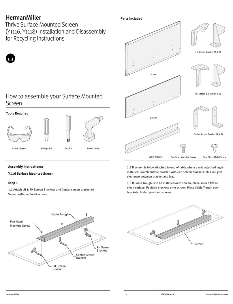
Herman Miller
Herman Miller Thrive Y1116 Installation and Disassembly for Recycling Instructions
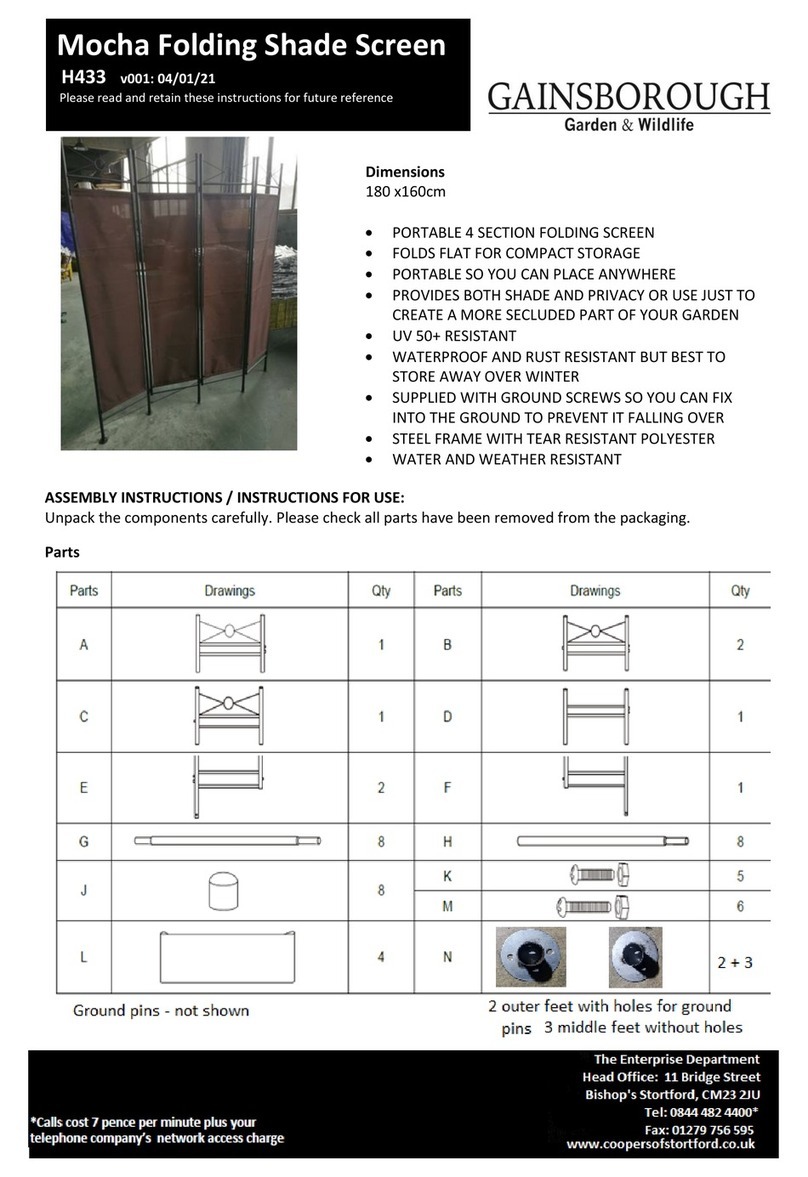
Gainsborough
Gainsborough H433 Instructions for use
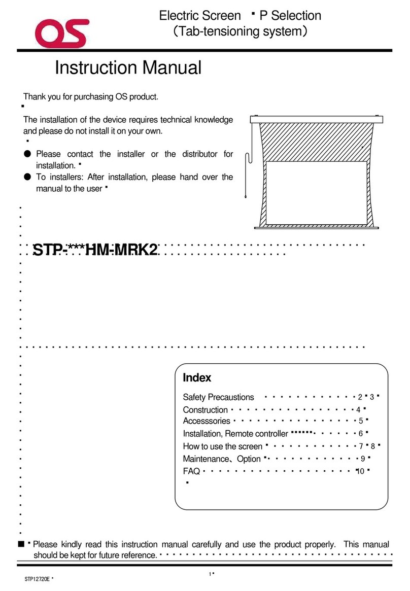
OS
OS STP-HM-MRK2 instruction manual
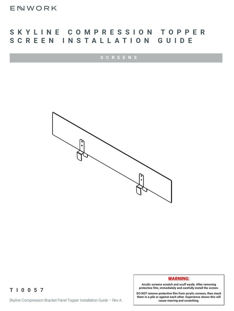
Enwork
Enwork Skyline installation guide
Elite Screens
Elite Screens Saker Tension Series user guide
