Flying Thingz M1A1 Flying Tank User manual
M1A1 Flying Tank
A Sport Scale Flying Military Tank
The M1A1 Flying Tank is fun and easy to build. We have done all the hard work for you. It can easi-
ly be framed up and covered in a weekend. While it may look a little bit different, the construction
techniques used are the same as most other airplanes. The average modeler will have no problem. You
will find top quality Laser Cut balsa, plastic and plywood, as well as beautiful CNC Cut foam cores
and parts! It is the ultimate high tech kit!
Low speed flying is great, with huge elevons and tons of surface area, it will crawl along with
full control and amazing stability. To speed up all you need to do is give it gas! It flies smooth, sta-
ble, and responds great. Most say that it flies like a low wing sport plane. Landings are breeze, just
lower the throttle and she’ll settle in on her own. All in all you can't find a plane that gets you more
attention and is as fun to fly.
Copyright © 2010 Kit# FTZ3015
Specifications
Wingspan: 24"
Wing Area: 864 sq in
Weight: 7 lbs.
Radio: 4 Channel w/ Elevon Mixing
Engine: .46 - .61 two-stroke / .53 - .71 four-stroke

2
Table of Contents
WarrantyInformation.................................................................................3
WarningsandSafetyPrecautions.......................................................................3
BeforeStartingAssembly..............................................................................3
UsingThisManual.................................................................................. .4
KitContents.........................................................................................4
AdditionalRequirements..............................................................................5
RequiredToolsandAdhesives.........................................................................5
FuselageAssembly....................................................................................6
PreparingtheFoam..................................................................................10
WingAssembly......................................................................................10
ElevonAssembly....................................................................................13
CoroplastPartsAssembly............................................................................13
FinalAssembly......................................................................................13
RadioSetup.........................................................................................16
ControlThrows&CG...............................................................................17
Pre-FlightChecklist..................................................................................17
FlightCharacteristics............................................................................ ....18
2004AMASafetyCode...............................................................................18

3
Warranty Information
FlyingThingZ, Inc. guarantees this model to be free from defects in material and workmanship at the date of purchase. This warranty
does not cover any parts damaged by use or modifications. In no way shall FlyingThingZ, Inc. liability exceed the original cost of the
purchased model. Further, FlyingThingZ, Inc. reserves the right to modify this warranty without prior notice.
In that FlyingThingZ, Inc. has no control over the final stages of assembly or material used for the final assembly, no liability shall be
assumed nor accepted for any damage of the final user-assembled product. By the act of using the final product, the user accepts all
resulting liability.
We, as a kit manufacture, provide you with a top quality kit and manual, but the quality and flying characteristics of your finished model
depend on how you build it; therefore, we cannot in any way guarantee the performance of your completed model and no representa-
tions are expressed or implied as to the performance or safety of your completed model.
If the buyer is not prepared to accept the liability associated with the use of this product, the buyer is advised to return this kit imme-
diately, in new and unused condition, to the place of purchase.
Warnings and Safety Precautions
READ THROUGH THIS MANUA BEFORE STARTING ASSEMB Y. IT CONTAINS IMPORTANT WARNINGS AND
INSTRUCTIONS CONCERNING THE ASSEMB Y AND USE OF THIS MODE .
AN RC AIRCRAFT IS NOT A TOY! IF MISUSED, IT CAN CAUSE SERIOUS BODI Y HARM AND DAMAGE TO PROPERTY.
F Y ON Y IN OPEN AREAS, PREFERAB Y AT AMA (www.modelaviation.com) APPROVED SITES. FO OW A INSTRUC-
TIONS INC UDED WITH YOUR RADIO AND ENGINE.
You must assemble the model according to the instructions. o not alter or modify the model, as doing so may result in an unsafe
or unstable aircraft. In a few cases the instructions may differ slightly from the images provided. In these cases, the written instructions
should take precedence.
Take your time to build straight, true and strong.
You must use an R/C radio system that is specifically designed for aircraft frequencies, properly tuned and in first class working
condition. The correctly sized engine displacements and miscellaneous components should be used throughout the building process as
specified on this manual.
Check the operation of your model before each flight and insure that all equipment is fully operational and all hardware is secure.
Be sure to check all linkage connections and parts that may become dislodged during flight.
This kit is not intended as a trainer. If you are not an experienced pilot, you should fly the model only with the help and supervi-
sion of a competent, experienced R/C pilot.
Before Starting the Assembly Process
Before beginning assembly of the M1A1 Flying Tank, remove all parts from their packages for inspection. Inspect all hardware, fuse-
lage parts, wing components and foam for damage. If you find any damaged or missing parts, please contact us directly.
FlyingThingZ, Inc.
2075 Grandview St.
Oceanside, CA 92054
www.flyingthingz.com
4
Using This Manual
This manual is divided into sections to aid in the assembly process. It provides an easier more concise layout allowing for breaks
between each major section. Additionally, check boxes have been provided next to each step to help keep track of the completed
assembly process. Steps with two check boxes indicate that the step is repeated, such as for a right and left wing panel, control link-
ages or fuselage side. Remember to take your time and follow the directions carefully.
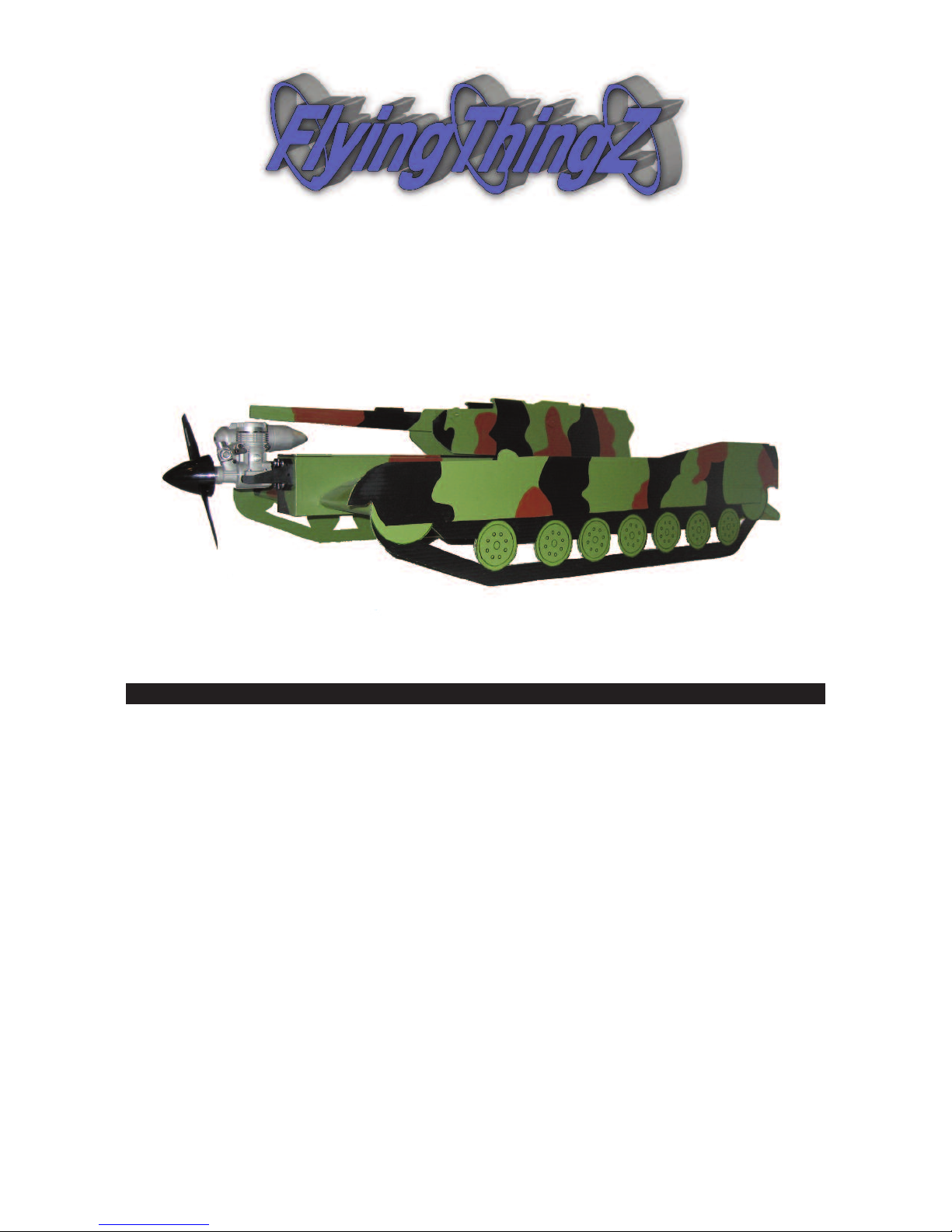
Kit Contents
Part# Description Qty.
AFuselage Hatch 1
BFuselage Reinforcements 2
CFirewall 2
DFuselage Sides 2
ERear Servo Tray 1
FForward Servo Tray 1
GFuselage Cross Brace 1
HHatch Tongue Plate 2
IGear Block Piece 6
JNotched Gear Block Piece 2
KRear Fuselage Plate 1
Lower Ply Fuselage Plate 1
MControl Horn 2
NNose Landing Gear 1
OMain Landing Gear 2
QHatch Tongue 1
RHatch Bolt Plate 1
Ply isks 4 (not shown)
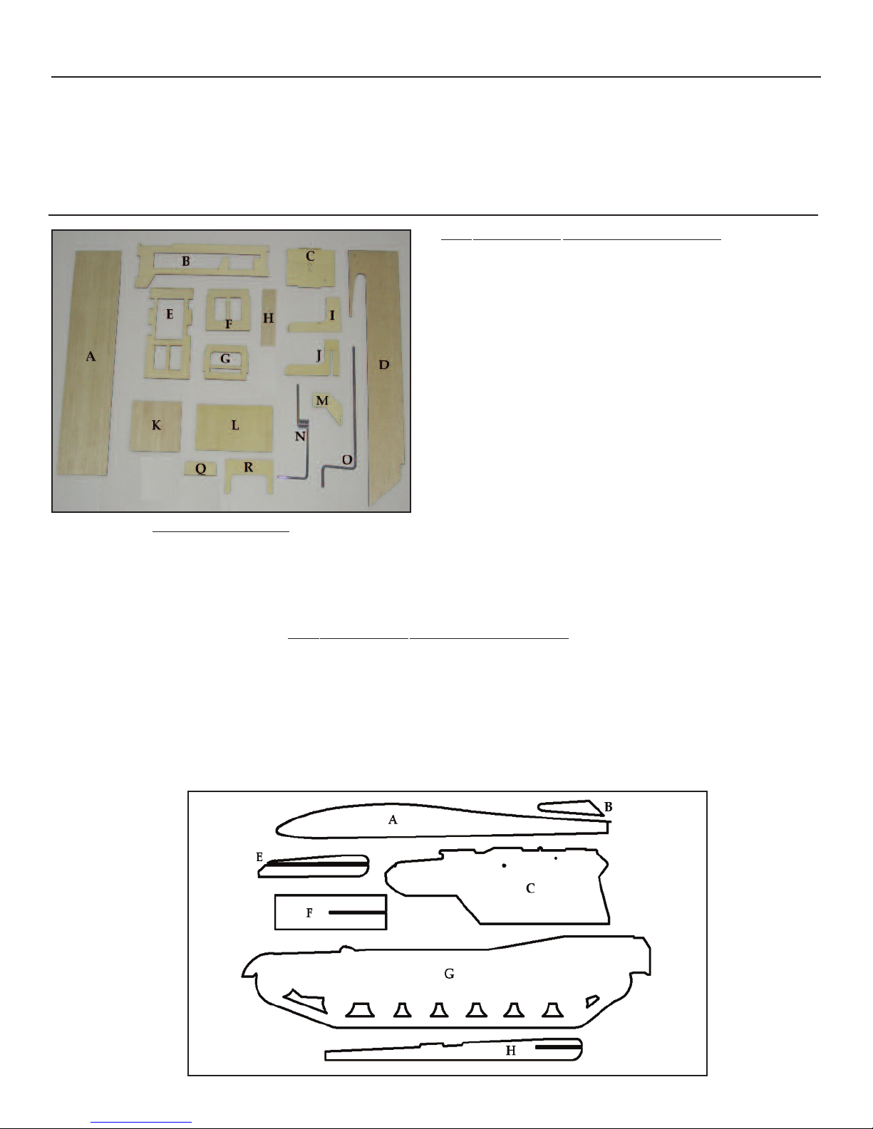
Part# Description Qty.
AWing Core 1
BElevons 1
CTank Turret 2
ECanon Reinforcements 4
FCanon Base 1
GTank Sides 2
HCanon 2
Wood Parts Not Shown
1/2” x 18” Balsa Triangle
1/16” x 4” x 36” Balsa Sheet
1/4” x 1/4” x 36” Balsa Stick
1/4” x 36” Wood owel

5
3 2.5” to 3” Wheels
Motor Mount and Mounting Hardware
2’ Medium Fuel Tubing
Prop Suited to Engine
2” Filament Strapping Tape
Engine - .40 to .60 two-stroke or .45 to .72 four-stroke
Rubber Foam
Low Temperature Covering Material
FlyingThingZ Pre-cut Self Adhesive Vinyl Covering
Clear Packing Tape
4 2-56 Pushrods
8oz. Fuel Tank
2” Spinner
4 Channel Radio with Elevon Mixing
3M Super 77 Spray Adhesive
Thin, Medium and Thick CA
5 minute and 30 minute Epoxy
CA Accelerator
White or Carpenter’s Wood Glue
Small Square
#120, #220, #320 Sand Paper
Sanding Block
Hobby Knife with Extra #11 Blades
Pen, Pencil or Marker
Assorted Screw rivers
Building Pins
Razor Saw
Miter Box
Masking Tape
Clamps or Clothespins
Wire Cutters
Needle Nose Pliers
Scissors
Wax Paper
Paper Towels
Ruler
Mixing Sticks
Threadlock
enatured Alcohol
Rotary Tool or remel
Router Attachment for Rotary Tool or remel
Rubber Bands
ead Center Engine Mount Locator
Hex Wrench Set
rill Bits (1/16” 3/32” 1/8” 5/64” and 1/2” bits)
Electric rill
Unless a specific glue is specified, use your best judgement when joining parts.
CA WI EAT FOAM. O NOT USE CA TO BON ANY PARTS TO FOAM.
Most of the tools listed herein come in handy when assembling parts provided by this kit. Although they are not all necessarily
required, they do make the process easier. You may substitute tools and other equipment listed here as long as they serve the same
purpose in a similar fashion.
Required Tools and Adhesives
Part Description Qty.
3/4” x 4-40 Bolts 1
4-40 Blind Nuts & Washers 1
Landing Gear Straps 4
Nose Gear Hardware 1
#2 x 9/16 Wood Screws 2
5/32” Wheel Collars 6
Additional Kit Contents (Not Shown)
Additional Kit Requirements
6
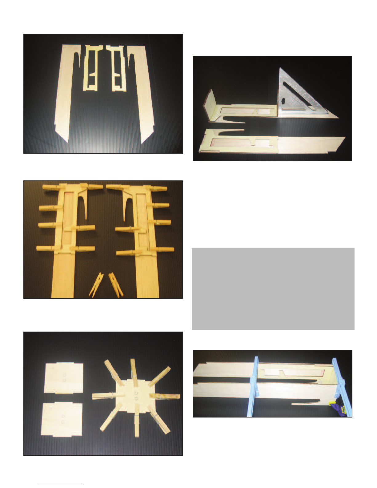
A. Fuselage Assembly
A1. Start by lining up the two fuselage sides and the two ply
fuselage reinforcements. Take note of the orientation to assure a
right and left fuselage side is created when assembled.
A2. Utilizing cloths pins, glue the fuselage reinforcements
onto the two fuselage sides. Line up the edges of the reinforce-
ments until they are flush with the three edges of the fuselage
sides.
A3. Glue the two ply firewall pieces utilizing clothe pins to
hold the parts together. Verify the orientation of the holes on the
firewall as they will play a vital role later on.
A4. Glue the fuselage cross brace to the back of the fuselage
reinforcement. Assure that the brace lines up with the notches on
the back of the reinforcement. Use a square to assure the brace is
90-deg. to the fuselage side.
A5. In the same fashion, glue the firewall to the front of the
fuselage reinforcement. Assure that the firewall lines up with the
notches in the front of the reinforcement. Again, use a square to
assure it’s at a perfect 90-deg. angle to the fuselage. The small hole
on the firewall should be on the top left when laid out as shown in
the photo above.
A6. Using clamps, glue the two fuselage sides together. The
firewall and cross brace should line up with the notches on the
other side of the fuselage reinforcement. Make sure pressure is
applied where the cross brace and the firewall meet the fuselage
sides. Make sure to apply pressure on the bottom part of the fire-
wall as well to create a strong bond.
Hints and Tips
You can substitute rubber bands or masking tape to hold parts
together. Flat parts can be sandwiched between books; just make
sure they don’t get stuck to the books.
You can make your own square by cutting a triangle out of card-
board exactly at 3” x 4” x 5”. If your measurements are correct,
this should make a perfect 90-deg angle.
Cut several paper towels into 4 pieces and soak them in alcohol.
Store them in a plastic zip bag to keep them from drying out. You
can use them to wipe up any excess epoxy while you work.

7
A7. Carefully insert the forward servo tray between the two
fuse sides. Make sure the back end butts up against the fuselage
cross brace, then glue into place.
A8. Slide the hatch bolt plate against the firewall. Line up the
flaps flush against the top of the firewall and clamp down as the
glue sets. Make sure the hatch bolt plate is on top of the fuselage.
A9. To prepare the rear part of the fuselage, use the rear servo
tray as a spacer and clamp down the two fuselage sides. O NOT
glue the rear servo tray at this time, it is only being used as a
spacer.
A10. Size and cut a hatch tongue plate and glue it to the notch-
es on the back of the fuselage. Sand the edges flush with the sides
of the fuselage. Sand the rearward part of the hatch tongue plate
to match the angle of the fuselage as shown in the image above.
A11. Glue the rear fuselage hatch plate to the back of the fuse-
lage. Sand the top of the fuselage rear plate flush with the hatch
tongue plate. Leave a 1/8” overhang on the bottom of the rear
fuse plate.
A12. Cut two pieces of balsa triangle to fit flush with the top
of the firewall. Glue the triangle onto the hatch bolt plate and the
sides of the fuselage and firewall

8
A13. Line up a piece of 1/4 x 1/4 balsa stick against the fuse-
lage cross brace. Scribe a line where the balsa stick lines up with
the hatch bolt plate. Cut the balsa stick along the line.
A14. Lay the fuselage assembly onto the fuselage hatch.
Make sure the hatch is flush along the sides of the fuselage and the
firewall. Glue the balsa stick onto the hatch only. The balsa stick
should only be glued to the hatch.
Avoid getting glue on the fuselage sides. Repeat on the other side.
A15. Flip the fuselage around until the bottom is facing up.
Glue the rear servo tray 1 - 1/2 inches from the bottom of the fuse-
lage. Make sure the tray is up against the fuselage cross brace.
A16. Cut two pieces of 1/4 x 1/4 balsa stick the same size as
the servo tray. Glue the balsa sticks to the sides of the fuse, the rear
servo tray and the fuselage cross brace. Cut the balsa stick at the
notches on the servo tray, you’ll need these notches to mount your
radio gear later.
A17. Reinstall the fuselage hatch and flip the fuselage around
so that the bottom is facing up. raw a line onto the fuselage
hatch across the hatch tongue plate. Extend the lines about 1/2”
along the sides of the fuselage.
A18. Cut a piece of the hatch tongue plate down to 3”. Center
and glue it onto the fuselage hatch 1/8” of an inch from line mark
made on the previous step.
A19. Glue the ply hatch tongue onto the hatch tongue plate.
Make sure it is centered and 3/8” from the front of the hatch
tongue plate. The lip should protrude towards the back of the
fuselage hatch. When the hatch is inserted onto the fuselage, the
fit should be snug. With the fuselage hatch installed, sand the
back edge of the hatch flush with the rear fuselage plate.

9
A20. Cut several pieces of the 1/16” balsa sheet. For added
strength make your cuts are against the grain. When installed on
the fuselage bottom, the grain on the 1/16” balsa sheet should be
running along the width of the fuselage, not it’s full length.
A21. Glue the 1/16” balsa sheets onto the bottom of the fuse-
lage. Sand all the edges flush with the sides and back end of the
fuselage. Remember, the grain on the 1/16” sheeting should run
along the width of the fuselage.
A22. Along the front of the fuselage, glue the lower ply fuse
plate flush with the edges of the fuselage sides and the firewall.
A23. Sand all rough edges of the fuselage to obtain a nice
smooth finish.
All parts should be flush with each other at all corners and edges.
A24. Fuel proof the firewall and internal components using
either epoxy or polyurethane.
The next steps outline covering the fuselage with our precut, self
adhesive vinyl covering. If you have elected to use another
material such as Monokote, the process will be very similar.
Please follow the manufacturer’s instructions on using their
material for covering.
A24. Lay a piece of the precut vinyl shaped like the fuselage
on your workbench. Place the fuselage onto the vinyl and cut slits
into the vinyl at the corners of the fuselage. Fold the corners over
onto the fuselage and trim any excess. Leave approximately 1/8”
to 1/4” overlap. Cut out the opening on the bottom of the fuselage
where it saddles onto the wing.
A25. Flip the fuselage over and do the same on the other side.
In the image above, you can see the cutout on the fuselage/wing
saddle mentioned in step A24.
A26. Cover the firewall and hatch bolt plate in the same man-
ner as the fuselage sides. Extend the covering onto the bottom
front of the fuselage right below the firewall. o not cover the
1/16” balsa sheeting on the bottom of the fuselage. This needs to
be exposed due to the fact that it will be expoxied to the wing in a
later step. In the same manner as the firewall, apply vinyl cover-
ing to the rear fuselage plate.
A27. In the same manner as the fuselage sides, cover the fuse-
lage hatch. Cut slits in the corners to make folding over easier.
Leave a 1/8” to 1/4” overlap on the bottom of the hatch.
The fuselage is now complete.
10
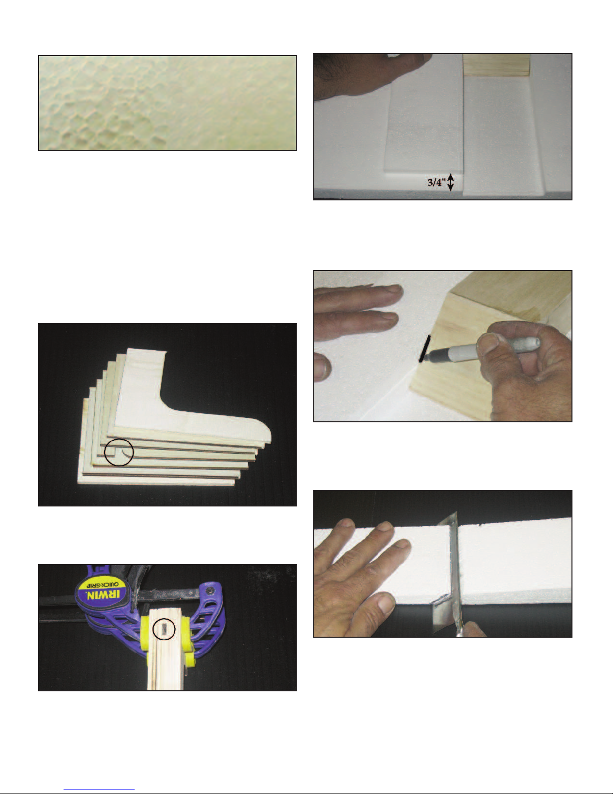
B. Preparing the Foam
B1. Sand the foam using #120 grit sand paper on a sanding
block. The foam should have a smooth texture after sanding is
completed. Be extremely careful not to distort the foam in any
way. Sand edges and curves very lightly. Enough pressure should
be applied to smooth out the foam, not to change its shape.
When sanding the leading edge’s airfoil, remove the sand paper
from the block and sand around the contour of the airfoil. Be care-
ful not to distort the airfoil. oing so will make the wing ineffi-
cient.
Smooth out all other foam parts in the same manner.
C. Wing Assembly
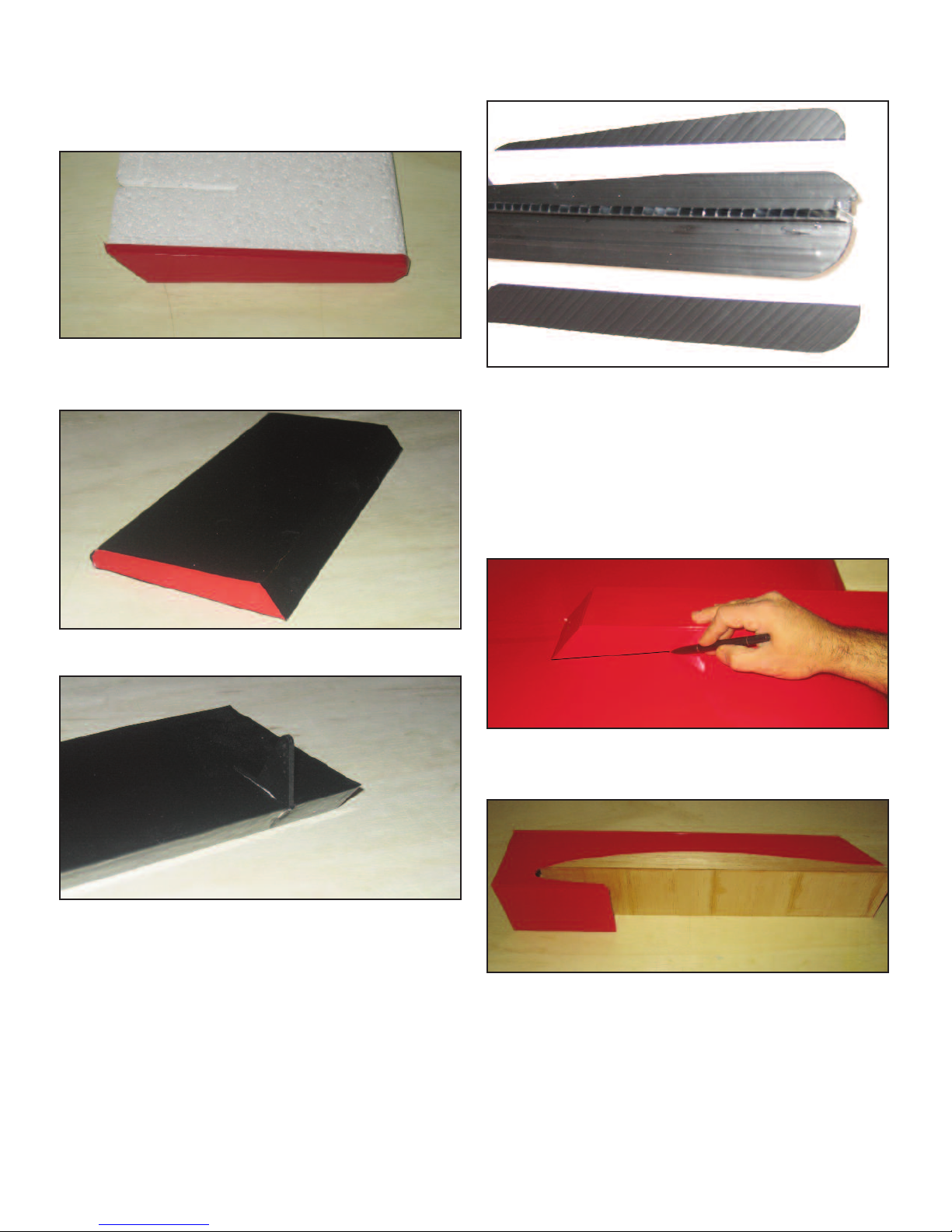
C1. Line up the gear block pieces and the notched gear block
piece as shown in the image above. The layout should be three
gear block pieces, a notched gear block piece, three more gear
block pieces.
C2. Glue the pieces together to form one gear block with a
notch in the middle as shown in the image above. Use clamps to
keep the assembly together as the glue sets. Once the glue has set,
sand all edges flush for a smooth finish.
C3. Remove the foam center insert from the wing core.
Temporarily install the fuselage into the leading edge of the wing
core and lay the foam center along the side of the fuselage. Place
the foam center 3/4” from the trailing edge of the wing. O NOT
GLUE THE FUSELAGE AT THIS TIME.
C4. With the fuselage in place and the foam center piece 3/4
of an inch from the trailing edge, make a mark along the back of
the fuselage onto the side of the foam center piece. The mark on
the foam center piece should be at the same angle as the fuselage
back plate.
C5. Extend your line all around the foam center. Using a
hobby saw or sharp hobby knife, cut along your line marks. Sand
the backing where the cut was made and check to make sure the
angle of the cut is the same as the angle of the fuselage back plate.

11
C6. Reinsert the cut foam center piece along the fuselage back
plate. If there is any excess overhang on the trailing edge, make a
mark and cut the excess until the back is flush with the trailing
edge. Sand as necessary to obtain a nice flush fit. Remove the
fuselage and glue the foam center piece flush with the trailing
edge. Avoid getting glue into the sides of the foam center piece.
You will need to route this area out later for the canon.
C7. Lay the wing core with the bottom facing up. From the
leading edge make a mark on the wing at 11” and 11 3/4”. To
obtain an accurate measurement, you can butt the leading edge of
the wing against a square, then butt the ruler against the same
square. You can also use a wall on the leading edge to serve the
same purpose if a square is not available.
C8. Lay the assembled gear block between the marks scribed
on the bottom of the wing core. Extend the lines around the out-
side edges of the assembled gear block. In the same fashion, scribe
marks along the side of the wing core following the smaller edges
of the assembled gear blocks.
C9. Using a rotary tool with a router attachment cut the foam
inside your line marks. The top portion should be at a depth of
11/16th of an inch. The side portion of the cut should be set at 1”
depth. Make sure you start your cuts inside your lines and test fit
the gear block often. The final fit should be snug and flush with
the edges of the wing core. When you are satisfied with the fit,
glue the gear blocks into place.
C10. Use a rotary tool to notch out 4mm of the gap between
the wing core and the foam center piece. Test fit the canon turrets.
C12. Temporarily insert the fuselage and test fit the canon tur-
ret. The front of the canon turret should be flush with the back of
the fuselage. Continue to make the cut deeper as needed to obtain
a good fit.
12
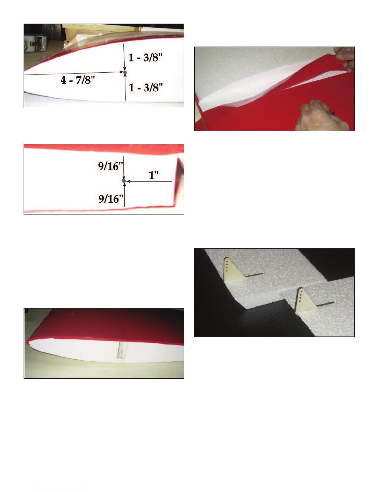
C13. Make a mark 4 - 7/8” from the leading edge centered on
the side of the wing core. In our model, the center point was 1 -
3/8” from the top and bottom. rill a 1/4” hole on the mark and
test fit a dowel. Repeat on the other side.
C14. Make a mark 1” from the trailing edge centered on the
side of the wing core. In our model, the center point was 9/16”
from the top and bottom. rill a 1/4” hole on the mark and test fit
a dowel. Repeat on the other side.
The next steps outline covering the wing with our precut, self
adhesive vinyl covering. Be extremely careful when using a heat
applied covering. High heat will distort the foam and perma-
nently ruin the wing shape. These steps are best performed with
some help. Apply a thin coat of Super 77 Spray Adhesive before
covering any foam parts.
C17. Cut a strip of vinyl to 27” long. Staring on the bottom of
the wing, scribe a mark near the leading and trailing edge 11 3/4”
from one side of the wing. Carefully lay the first piece of covering
along the two marks centered on the wing. Squeeze out any air
bubbles starting in the middle and work your way out towards the
edges. Overlap the trailing edge, but do go onto the top of the
wing. Cut off any excess at the trailing edge. For the leading edge,
only overlap to the very tip of the leading edge. Cut off any excess
beyond the tip of the leading edge. The sides of the wing should
have about 1/8” to 1/4” overhand on the sides. You may need to
cut slits into the vinyl to follow the contour of the wing.
Repeat for the other half of the wing bottom. The two pieces of
vinyl covering should leave an overlap in the middle approxi-
mately 1/4”.
C18. On the wings top, scribe a mark 11 3/4” from the side of
the wing on both the leading and trailing edge. Using another
piece of vinyl cut at 27” lay the covering along the marks on top of
the wing. Squeeze out any air bubbles starting in the middle and
work your way out towards the edges. Cut away any excess vinyl
over the wing center cutout leaving approximately 1/8” to 1/4”
overlay. Fold over the excess into the center cutout area. Wrap the
covering 1/2 through the back of the trailing edge and cut off any
excess. Wrap the covering beyond the leading edge to the bottom
of the wing approximately 2” and cut off any excess.
Repeat for the other half of the wing top. The two pieces of vinyl
covering should leave an overlap in the middle approximately
1/4”.
D. Elevon Assembly
1. Lay out the left elevon and make a line 2” long that is 3/4”
away from the right side. On the right elevon, do the same, but
measure the 3/4” from the left of the elevon. Make sure they are
on the forward part of the elevon as shown in the photo above.
2. Using a rotary tool or drill, make a 1/16” slot on the 2”
line all the way through the elevon. You may want to use a square
to assure your cut is perfectly straight. Test fit the control horns,
they should fit snug and should be flush with the edges of elevon.
The edges of the control horns should match the contours of the
elevon. Sand as necessary to obtain a good fit.
O NOT GLUE THE CONTROL HORNS AT THIS TIME.
13
The next steps outline covering the elevons with our precut, self
adhesive vinyl covering. Be extremely careful when using a heat
applied covering. High heat will distort the foam and perma-
nently ruin the elevon’s shape. Apply a thin coat of Super 77
Spray Adhesive before covering any foam parts.
3. Start by covering the outside edges of the elevons. Cut
slits into the vinyl around edges to help fold over the curves.
Overlap 1/8” to 1/4” of the covering around all the edges.
4. Using a larger piece of covering, wrap the elevon in the
vinyl. Cut away all excess.
5. Find the location of the control horn slots. Using a hobby
knife, cut a slit into the covering over the control horn cutout.
Using epoxy, glue the control horns in place. The control horn
should be painted prior to installation. This will help to conceal
the control horns and protects them against the fuel and exhaust.
E. Coroplast Parts Assembly
E1. Cover or paint the canon parts in the same fashion as the
fuselage. Cut slits along curves to allow for the covering to wrap
properly around the edges.
E2. Assemble the canon parts by sliding the two canon parts
into thier base unit. Epoxy the canon into place and attach the top
and bottom canon reinforcements.
G. Final Assembly
G1. Temporarily attach the fuselage to the wing. Use a felt tip
non-permanent marker to outline the shape of the wing onto the
fuselage.
G2. Cut out the covering approximately 1/8” down from the
line your created and remove the covering from this area. Wipe up
any marker lines with a rag and alcohol.
14
G3. Use a liberal amount of 30 minute epoxy on the wings cen-
ter cut out and the bottom of the fuselage. Slide the fuselage into
the wing until the back of the fuselage is flush with the back of the
wing center piece. Make sure the fuselage saddle is seated well on
the leading edge of the wing. Wipe up and excess epoxy before it
dries.
G4. Cut the two slit along the previously created 1/8” line on
the sides of the center cutout. Try to make the cut as centered as
possible. o not remove the excess covering, it will fold into the
cutout and provide a snugger fit for the canon turret. Using a lib-
eral amount of epoxy, glue the tank turret into the wing core. Use
a level to assure a 90 degree angle.
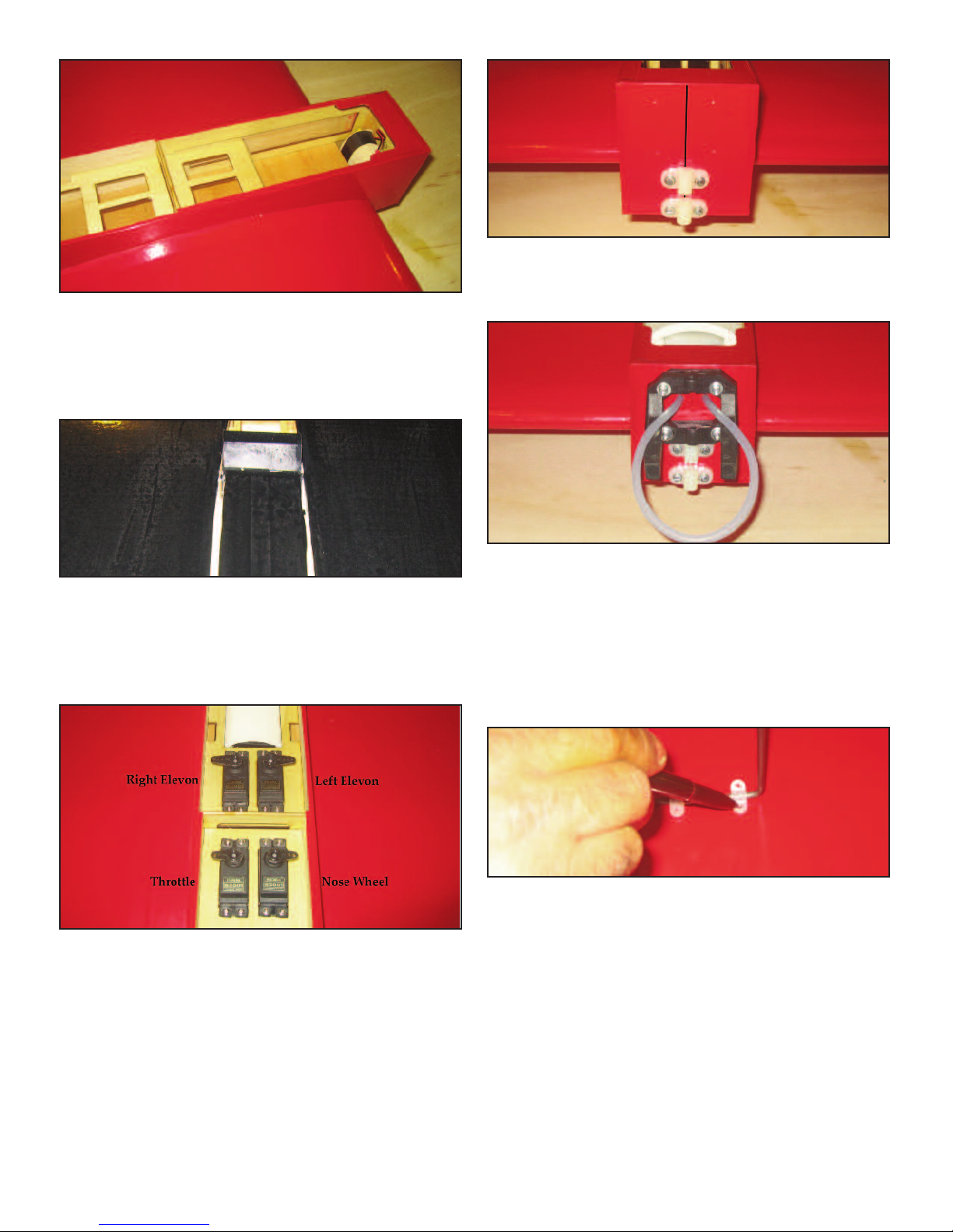
G5. Lay out the servos as shown in the image above. Use a
dead center tool to make the pilot holes for the servo’s self tapping
screws. Use your radio manufacturer’s instructions on installing
the rubber grommets on your servos. Wrap your receiver in foam
and place into the rear servo tray opening. The battery is placed
in the compartment right behind the firewall.
G6. Scribe a center line on the front of the firewall. Center the
nose gear mounting brackets against your line and flush with the
bottom of the firewall. Use a dead center tool to create pilot holes
and mount using the provided self tapping screws.
G7. Center the motor mount on the scribed center line flush
against the nose gear brackets. Use a dead center tool create pilot
holes. Enlarge the pilot holes and install the motor mount using
the appropriately sized blind nuts, bolts and washers to suit your
motor mount. rill out the two precut holes in the center cutout
of the motor mount for your fuel lines. The fuel tank goes right
behind your battery pack directly in front of the forward servo
tray. Wrap the fuel tank with foam rubber to prevent bubbles from
forming due to vibration.
G8. Use a 5/32” drill bit to clean out the cutout on the land-
ing gear block located under the wing. rill only deep enough for
the 5/32” rod to fit. Use a dead center tool to make pilot holes
using the provided main gear mounting brackets as a guide.
Secure the main landing gear with the self tapping screws and
nylon brackets provided.
15
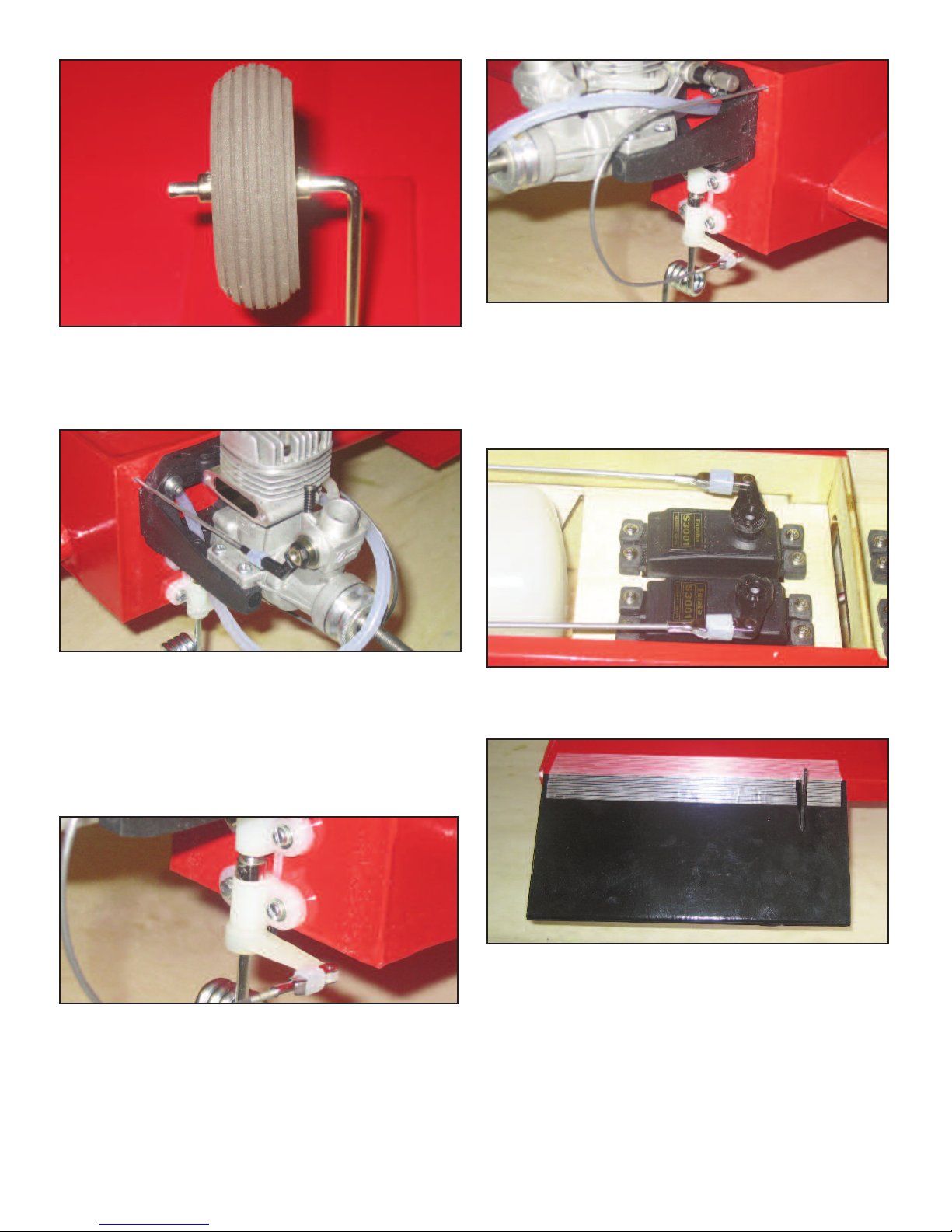
G9. Temporarily slide a wheel collar into the landing gear rod,
then a wheel then another wheel collar. Mark the locations of the
wheel collars. Using a dremel or rotary tool, grind a flat spot onto
the landing gear wire so that the wheel collar set screws have
something flat to bite into. Reinstall the wheel and wheel collars.
G10. Install the engine onto the motor mount. Place the
engine as close to the tip of the motor mount as possible. Using a
dead center tool, mark the screw location onto the motor mount
and drill the pilot holes to accommodate a #6 x 3/4” self tapping
screw. Use the throttle lever to align the control rod and mark the
location onto the firewall. rill a hole to accommodate the throt-
tle control rod. Install a clevis onto the control rod and connect it
to the throttle level.
G11. Install the nose gear wire into the brackets by placing
the spacer between the two brackets then inserting the control arm
on the bottom of the brackets. Insert the nose gear through the
control horn, the first bracket, the space, then the top bracket. The
top of the wire should butt up against the bottom of the motor
mount. o not change the length of the nose wire, it should bring
the nose slightly higher than the rest of the model.
G12. Using 4-40 rod, make a bend outlined in the image above
as a sample.
Align the rod with the control horn and mark a location on the
firewall to run directly back to the rudder servo. Attach a clevis to
the end of the rod and connect it to the outer most hole on the con-
trol horn. Run the other end of rod through the firewall hole
towards the rudder servo.
G13. Size the control rods to reach the outer most hole of your
servo control horns. We opted to use solder clevises, but quick
connectors or nylon clevises will work as well.
G14. Use a strip of 2” filament tape (strapping tape) to attach
the elevons to the trailing edge of the wing.. Use one strip of tape
on the top and one on the bottom of the elevon joint. Make sure
the tape follows the contours of the elevon for a silky smooth oper-
ation. Apply a strip of the appropriately colored vinyl over the
strapping tape.

16
G15. Attach a clevis to one end of a control rod and attach it
to your servo control horn. Find a suitable exit point either on the
side of the fuselage or through the rear fuselage plate. The image
above shows the option going through the side of the fuselage.
Cut the control rod to a suitable size to fit onto the elevon control
horns and attach with a clevis.
G16. Insert 2 dowels into the 1/4 holes on the side of the wing
core. They will be used as guides to line up the tank sides. Lay the
wing core on top of a spoiler support bracket and tank sides.
Make a mark onto the tank sides and spoiler support bracket.
Remove the covering 1/8” from the line you scribed. Using a lib-
eral amount of glue and attach the spoiler support bracket and
tank sides to the wing core. Make sure the dowels are flush with
the tank sides. The dowel will be concealled with a wheel decal
provided in our covering kit.
G17. Assembly the tank canon stays by epoxing one disk onto
the carbon rod. Slide the assembly through the holes on the turret
and through the canon. Tie it all together by screwing the oppo-
site side in place.
Apply a dab of oil on the screw to avoid cracking the carbon rod.
H. Radio Setup
H1. Turn on the transmitter then the receiver and center the
trims. If necessary, remove and adjust the control clevises or the
servo control horns to obtain a centered position.
H2. Make certain that the controls surfaces respond in the cor-
rect direction as shown in the diagrams. If any of the controls
respond in the wrong direction, use the servo reversing function in
your transmitter.
eft Stick Throttle: When moved up, the carburetor should open
fully. When brought down, the carburetor should close.
eft Stick Rudder: When turned right, the steering wheel should
turn right. When turned left, the steering wheel should turn left.
Right Stick Elevator: When moved up, both elevons should move
down. When moved down, both elevons should move up.
Right Stick Aileron: When turned right, the left elevon should
move down and the right elevon should move up. When turning
left, the left elevon should move up and the right elevon should
move down.
Note: Check all control surface movement looking at the model
from behind.
17
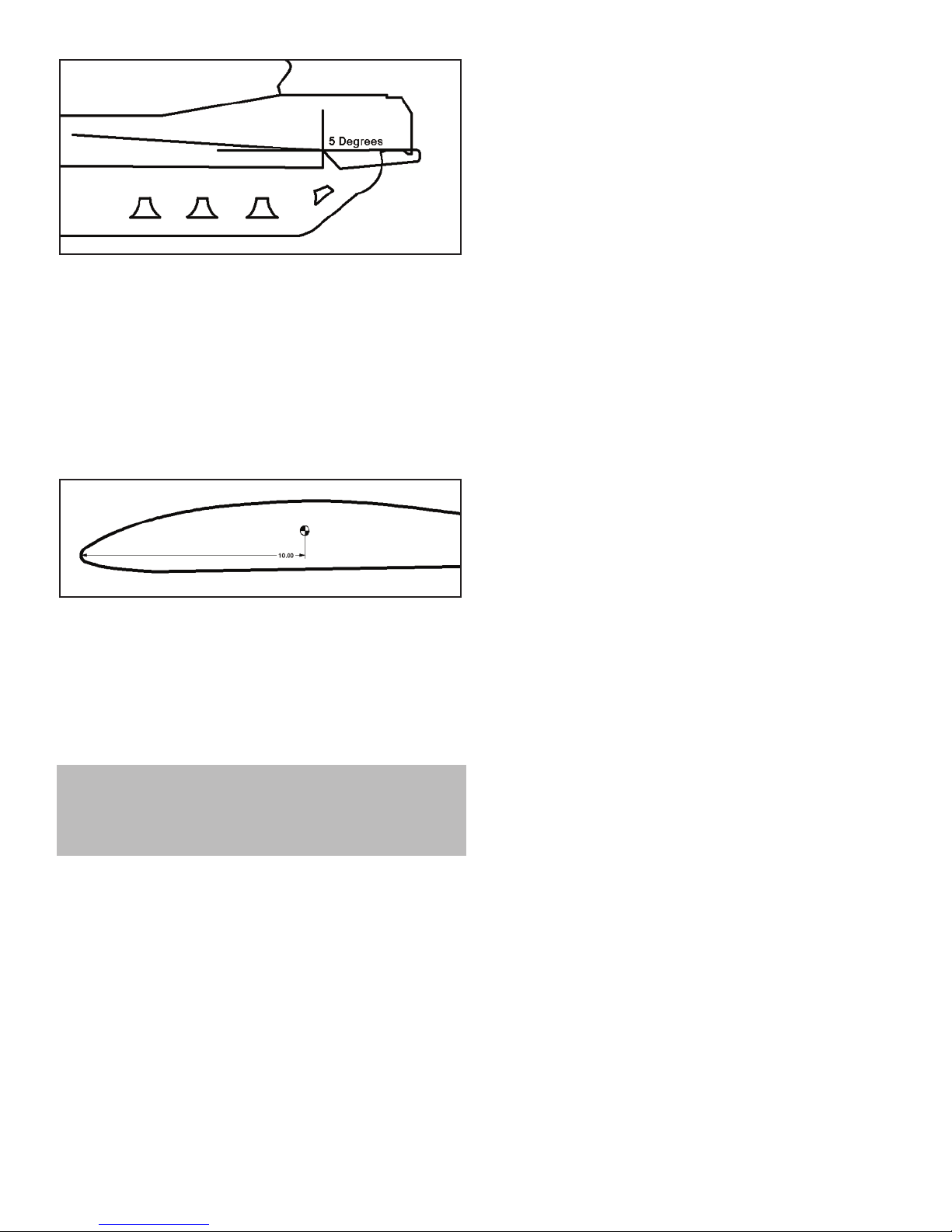
H3. For straight and level flight, the Tank’s elevons should be
set at 3 to 5 degrees of up elevator.
I. Control Throws & Center of Gravity (CG)
I1. We recommend a total of 3/4” of up and down throw for
the ailerons and elevators for low rates. For high rates set both to
1 1/2” of up and down throw. Exceeding this limit may cause the
model to become unstable in flight. You can experiment by
increasing or decreasing the throws with the dual rate function of
your transmitter.
I2. The M1A1 Flying Tank should balance as close as possible
to it’s center of gravity. The center of gravity on this model is 8” to
9 ” back from the leading edge of the wing. For initial flights, we
recommend setting the CG as close as possible to 8”.
If the tail drops from the CG point then the model is tail heavy and
requires weight up front. If the nose drops, the model is nose
heavy and requires weight in the rear.
Pre-Flight Checklist
Fuelproof all areas exposed to fuel or exhaust residue such
as the wing, fuselage, handle bars and firewall.
Check the CG according to the measurements provided in step
in this manual
Be sure the battery and receiver are securely mounted and cov-
ered in protective foam.
Make sure your receiver antenna is fully extended and there
is a strain relief in place to prevent it from being pulled from the
receiver housing. o not cut any excess antenna wire.
Use a threadlocking compound on all metal to metal fasteners
such as nuts, bolts and set screws.
Add a few drops of oil to the wheel axles so that they spin
freely.
Make sure all hinges are secure.
Reinforce holes for wood screws with CA where appropriate.
Confirm all controls operate freely and in the correct direction.
Make sure that throws are set as specified in this manual.
Make sure there are silicon retainers on all clevises, and the
servo horns are secured to the servo.
Make sure all your wire connections are secure and in good
physical condition.
Make sure your fuel lines are connected and are not kinked.
Balance your propeller to assure minimal vibration. Make
sure the prop nut is fully fastened.
Place your name, address, AMA number and telephone num-
ber on or inside your model.
Cycle all battery packs and make sure they are fully charged
before flying.
Range check your radio at the flying field before the first flight
following the radio manufacturer’s instructions.
More than any other factor, the CG can have the greatest effect on
how this model flies and may determine if your first flight will be
successful or not. O NOT OVERLOOK BALANCING YOUR
MO EL. Failure to properly balance this model may make it
unstable and possibly unflyable.

18
Flight Characteristics
Take Off: Line up on the runway and slowly advance the throttle.
Apply some down elevator to keep the tank from taking off before
obtaining take off speed. In crosswinds, it’s more important to
apply enough down elevator to keep the tank from flipping over.
Once flight speed is achieved, slowly add up elevator to take off.
The Tank will easily lift off and climb as long as enough speed is
obtained on the ground.
ow Speed Flight: The Tank will float around nicely at slow
speeds. Expect a high nose angle at slower speeds. Practice slow
speed high nose attitudes up high in preparation for landing. Get
used to this angle in the air up high as it will play a vital roll for
landing.
High Speed Flight: With a .61, the Tank really moves through the
air even at 1/2 throttle. It remains steady and predictable.
Aerobatics: The Tank will loop, roll. Make sure all initial aero-
batics are performed high to get a feel for any unusual tendencies
before bringing it down on the deck. We were not able to fly the
tank inverted.
All attempts ended in the tank going into an inverted flat spin.
Any inital inverted attempts should be made with enough altitude
to bail out.
anding: If setup according to this manual, the Tank will come in
slow with a high angle of attack. When landing, the elevons do lit-
tle work. Adjust the throttle as necessary to flare at the bottom of
your approach. Practicing this up high will make landings a snap.
2004 Official AMA National Model Aircraft Safety Code
Effective January 1, 2004
General
1) I will not fly my model aircraft in sanctioned events, airshows,
or model flying demonstrations until it has been proven to be air-
worthy by having been previously, successfully flight
tested.
2) I will not fly my model higher than approximately 400 feet
within 3 miles of an airport without notifying the airport opera-
tor. I will give right-of-way and avoid flying in the proximity
of full-scale aircraft. Where necessary, an observer shall be uti-
lized to supervise flying to avoid having models fly in the prox-
imity of full-scale aircraft.
3) Where established, I will abide by the safety rules for the fly-
ing site I use, and I will not willfully and deliberately fly my
models in a careless, reckless and/or dangerous manner.
4) The maximum takeoff weight of a model with fuel is 55
pounds, except models flown under Experimental Aircraft rules,
ocument Number 549*.
5) I will not fly my model unless it is identified with my name
and address or AMA number, on or in the model. Note: This
does not apply to models while being flown indoors.
6) I will not operate models with metal-bladed propellers or with
gaseous boosts, in which gases other than air enter their internal
combustion engine(s); nor will I operate models with extremely
hazardous fuels such as those containing tetranitromethane or
hydrazine.
7) I will not operate models with pyrotechnics (any device that
explodes, burns, or propels a projectile of any kind) including,
but not limited to, rockets, explosive bombs dropped from
models, smoke bombs, all explosive gases (such as hydrogen
filled balloons), ground mounted devices launching a projectile.
The only exceptions permitted are rockets flown in accordance
with the National Model Rocketry Safety Code or those perma-
nently attached (as per JATO use); also those items authorized for
Air Show Team use as defined by AST Advisory Committee (doc-
ument available from AMA HQ). In any case, models using rock-
et motors as a primary means of propulsion are limited to a max-
imum weight of 3.3 pounds and a G series motor. A model air-
craft is defined as a non-human-carrying device capable of sus-
tained flight in the atmosphere not exceeding the limitations
established in this Code, exclusively for recreation, sport, and/or
competition activities. The operators of radio control model air-
craft shall control the aircraft from the ground and maintain
unenhanced visual contact with t he aircraft throughout the
entire flight operation. No aircraft shall be equipped with
devices that would allow for autonomous flight.
8) I will not consume alcoholic beverages prior to, nor during,
participation in any model operations.
9) Children under 6 years old are only allowed on the flight line
as a pilot or while under flight instruction.
Radio Control
1) I will have completed a successful radio equipment ground
range check before the first flight of a new or repaired model.
2) I will not fly my model aircraft in the presence of spectators
until I become a qualified flier, unless assisted by an experienced
helper.
3) At all flying sites a straight or curved line(s) must be estab-
lished in front of which all flying takes place with the other side
for spectators. Only personnel involved with flying the
aircraft are allowed at or in the front of the flight line. Intentional
flying behind the flight line is prohibited.
4) I will operate my model using only radio control frequencies
currently allowed by the Federal Communications Commission.
(Only properly licensed Amateurs are authorized to
operate equipment on Amateur Band frequencies.)
5) I will not knowingly operate my model within three miles of
any pre-existing flying site except in accordance with the fre-
quency sharing agreement listed below in this paragraph. Flying
sites separated by three miles or more are considered safe from
site-to site interference, even when both sites use the same fre-
quencies. Any circumstances under three miles separation require
a frequency management arrangement which may be either an
allocation of specific frequencies for each site or testing to deter-
mine that freedom from interference exists. Allocation plans or
interference test reports shall be signed by the parties involved
and provided to AMA Headquarters. ocuments of agreement
and reports may exist between (1) two or more AMA Chartered
Clubs, (2) AMA clubs and individual AMA members not associ-
ated with AMA Clubs, or (3) two or more individual AMA mem-
bers, ocument Number 551*.

19
6) For Combat, distance between combat engagement line and
spectator line will be 500 feet per cubic inch of engine displace-
ment. (Example: .40 engine = 200 feet.); electric motors will be
based on equivalent combustion engine size. Additional safety
requirements will be per the RC Combat section of the current
Competition Regulations.
7) At air shows or model flying demonstrations a single straight
line must be established, one side of which is for flying, with the
other side for spectators.
8) With the exception of events flown under AMA Competition
rules, after launch, except for pilots or helpers being used, no
powered model may be flown closer than 25 feet to any person.
9) Under no circumstances may a pilot or other person touch a
powered model in flight; nor should any part of the model other
than the landing gear, intentionally touch the ground, except
while landing.
10) All officials, callers, and contestants must properly wear hel-
mets, which are OSHA, OT, ANSI, SNELL, OR NOCSAE
approved or comparable standard while on the race course with
aircraft(s) in flight.
Organized RC Racing Event
11) An RC racing event, whether or not an AMA Rule Book
event, is one in which model aircraft compete in flight over a pre-
scribed course with the objective of finishing the course faster to
determine the winner.
A. In every organized racing event in which contestants,
callers and officials are on the same course:
1. All officials will be off the course except for the starter
and their assistant.
2. “On the course” is defined to mean any area beyond the
pilot/staging area where actual flying takes place.
B. I will not fly my model aircraft in any organized racing
event which does not comply with paragraph A above or which
allows models over 20 pounds unless that competition event is
AMA sanctioned.
C. istance from the pylon to the nearest spectator (line) will
be in accordance with the current Competition Regulations under
the RC Pylon Racing section for the specific event pending two
or three pylon course layout.
12) R/C Night Flying is limited to low performance models (less
than 100 m.p.h.). The models must be equipped with a lighting
system that clearly defines the aircrafts attitude at all times.
Other Unique and Fun Kits from FlyingThingZ
Witch Wilga
Wing Span: 72” 60” Length
Flag Ship .40
Wing Span: 24.5” Chord 30”
Sky Cutter .40 V2
Wing Span 24.5” Chord 24.5”
Indy Sport Car
Wing Span 24.5” Chord 30”

Table of contents
Other Flying Thingz Toy manuals


Popular Toy manuals by other brands


Fisher-Price
Fisher-Price imaginext Pirate's Island B1473 quick start guide

MinimumRC
MinimumRC F8F Rare Bear Install manual

UGEARS
UGEARS Set of rails with crossing Assembly instructions

Velleman
Velleman XMDH1 user manual

Galak Electronics
Galak Electronics VG-212 manual

Eduard
Eduard Me 262A Schwalbe quick start guide