IINNSSTTAALLLLIINNGGTTHHEEAAPPPPLLIIAANNCCEE
To ensure the appliance is positively located into position, it is necessary to secure it in
place using one of the following methods, either with the cable fixing kit, or the double-
sided neoprene strips included in the instruction pack. Freestanding fires should use the
neoprene strip method only.
Fixxing bbynneoprene sstrips
In normal installation circumstances, this method of fixing is satisfactory for use with marble,
stone, laminate, or any smooth faced mounting surface. Peel off the adhesive backing from
one side of each strip and apply to the periphery of the REAR of the appliance frame, as
shown in the Fig.1. Ensure that the strips are not applied any closer than 5mm (1/4”) from the
edge of the frame, attaching the strips closer may present problems when fitting the decora-
tive trim. Tear off any excess lengths of strip to form a neat border around the frame.
Before finally fitting the appliance into its location, remove the remaining strips of adhesive
backing, ensure that the mains cable and plug are properly routed, locate the fire into the
opening and press firmly around the edge of the frame to allow the strips to adhere to the
back panel of the surround.
Fixxing bbyccable ffixxing kkit
This method of securing is normally necessary when the mounting surface is of a rough tex-
ture, i.e. stone or brick.
Firstly mark and drill a suitably sized hole in the centre of the proposed appliance location,
250mm up from the hearth surface, or floor if no hearth is to be used. Insert the rawlplug into
the hole, then screw in the eyebolt.
Withdraw the fuel bed and then the transparent flame effect screen by removing the two
screen clamps, which are each held in place by two screws, one at the base the other at the
top in to the hood. Insert the cable through the central hole in the back of the appliance
(Fig.2), through the eyebolt and through the hole in the lower rear of the appliance. The
screen can now be refitted with the textured side facing forward and secured under the
screen clamps (reversing the previously described method), adjust the screens height to suit
the fuel beds ‘legs.’ Remove the light bulb from its mounting by pushing it in and twisting.
Thread the cable through the small hole in the front panel. Locate the appliance into its open-
ing and pull the cable taught. Slide on the screwed nipple and keeping the cable reasonably
taught, tighten the nipple to secure (Fig.3). Replace the light bulb. The remainder of the cable
may be coiled up and tucked behind the front when fitted, or fed back into the appliance
through the hole and neatly coiled in the base, ensuring it does not come in to contact with
any part of the flame effect motor. Fit the fuel bed and decorative cast front.
NOTE: When uusing tthis ccable ffixing mmethod,,tthe aadditional ddepth ooftthe eeyebolt mmust bbe
taken iinto aaccount. TTherefore,,uusing tthis mmethod wwill iincrease tthe mminimum mmounting ddepth
of tthe aappliance bby220mm.
FITTING THE DECORATIVE FRAME AND FRONT
The appliance may be supplied with a decorative frame in a variety of finishes.
IMPORTANT ::DDue ttotthe ppossibility oofssharp eedges,,ccare sshould bbettaken wwhen hhandling tthe
three-ppiece fframe ccomponents. TThe uuse oofpprotective ggloves iisrrecommended.
If not pre-fitted, the clip-on frame pieces should be hooked over the outer edges of the
fireframe, and pushed firmly home. The sides should be fixed first, followed by the top bar,
which overlaps the sides. Push firmly home. A plastic protective film may be applied to the out-
side of the frame and should be removed at this stage.
Fit the firefront brackets (not required with Elegance models) under the screws that secure the
lower front panel on either side (fig.3). Fold the brackets along the ‘stitch bend’ so that they fit
inside the decorative firefronts sides. Place the decorative firefront in front of the fire and slide
the ashpan door into place.
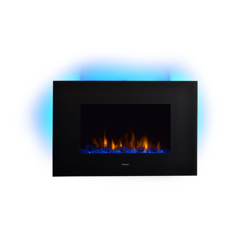
OPERATING THE APPLIANCE
Check that the fan outlet is not covered or obstructed in any way and ensure the power to the fire is switched on.
The appliance is controlled using four switches, mounted under the lift up hood. The left switch (OI) controls the main power to the fire and
switches on the fuel effect, which can be used independently of heat for visual effect only. The second switch (*) operates the fan blower
without heat, which can be used in the summer for cool air circulation. The switch marked with a single bar (I) operates the fan heater on
the LOW setting. The switch marked with two bars (II) operates the fan heater on the HIGH setting.
To operate the fire, the left switch must be turned on first, followed by the second switch to start the blower, if required. To obtain heat from
the appliance, the Iswitch must then be operated for LOW of heat, followed by the II switch for the HIGH setting. It is not possible to obtain
heat from the appliance without first switching on the main power switch (OI) and the fan blower switch (*) in conjunction with either the
LOW (I) or both the LOW and HIGH (II) switches.
Neoprene Strip
Fig. 1
Cable
Eyebolt screwed
into rear of
opening
5.0
5.1
6.0
2
Cable
Fig.3
Lower Front Panel
Screwed Nipple
Fret
bracket
Fig. 2


