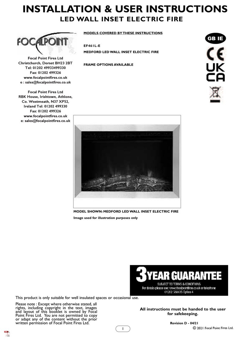
Focal Point AVANT User guide


Table of contents
Other Focal Point Indoor Fireplace manuals
Focal Point
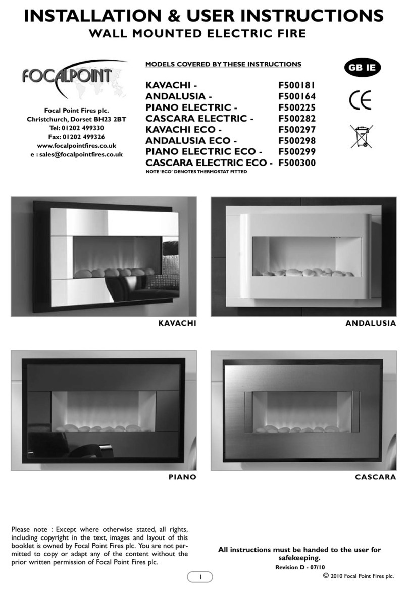
Focal Point KAVACHI F500181 Assembly Instructions
Focal Point
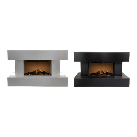
Focal Point DS-EHS01-41E Assembly Instructions
Focal Point
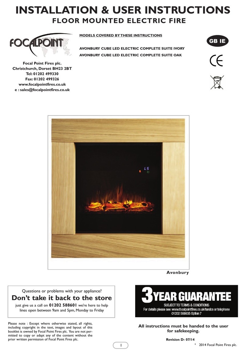
Focal Point AVONBURY CUBE LED ELECTRIC COMPLETE SUITE... Assembly Instructions

Focal Point
Focal Point EVOKE LED ELECTRIC Assembly Instructions
Focal Point
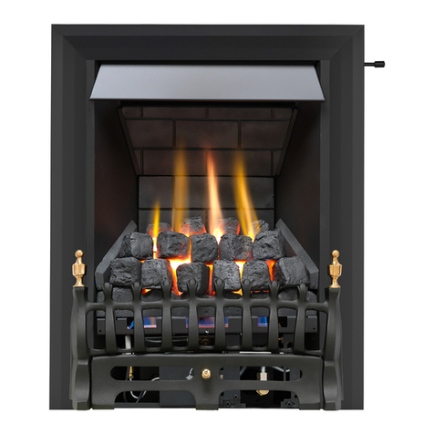
Focal Point MULTIFLUE GAS FIRE RANGE Guide

Focal Point
Focal Point HANNINGTON Assembly Instructions

Focal Point
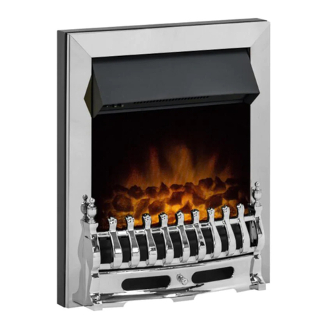
Focal Point BLENHEIM Assembly Instructions
Focal Point
Focal Point GRANGE MULTIFLUE Assembly Instructions

Focal Point
Focal Point Vogue Guide
Focal Point
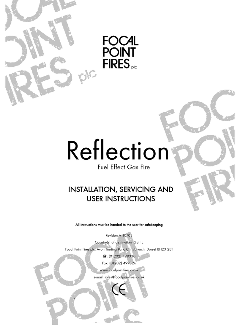
Focal Point REFLECTION User guide

Focal Point
Focal Point AMERSHAM LED ELECTRIC SUITE Assembly Instructions
Focal Point
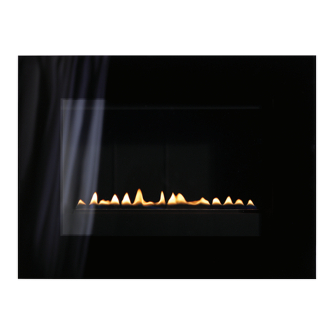
Focal Point L23 Series Assembly Instructions

Focal Point
Focal Point FPFBQ390 WICHITA FIRE SURROUND WHITE Programming manual
Focal Point
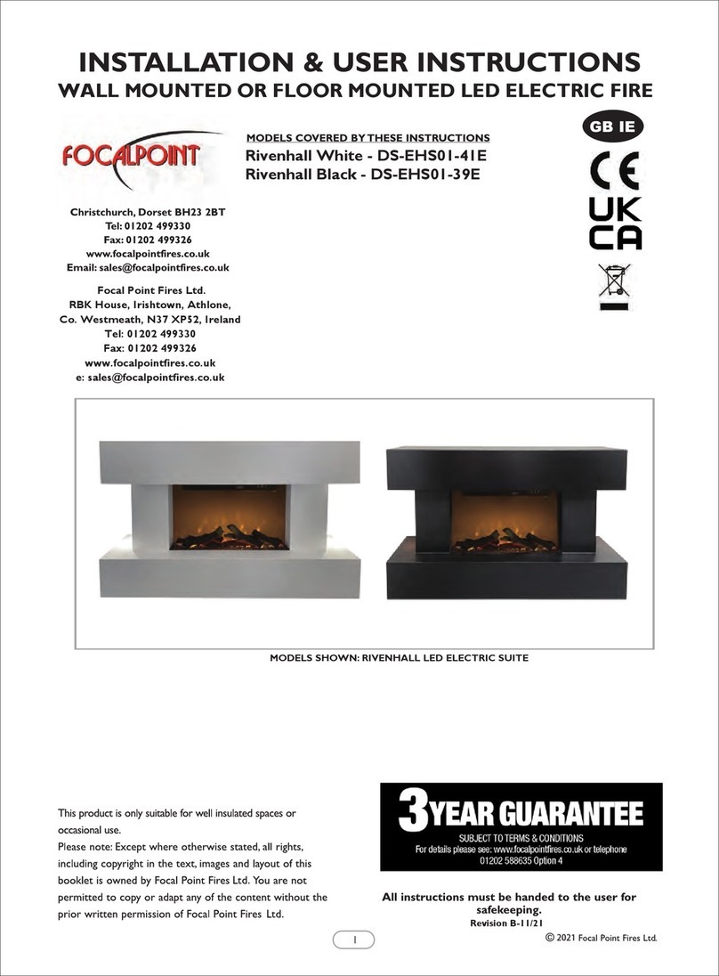
Focal Point Rivenhall DS-EHS01-41E Assembly Instructions
Focal Point
Focal Point F500116 User manual

Focal Point
Focal Point L23S MIDNIGHT Assembly Instructions

Focal Point
Focal Point REFLECTION Guide
Focal Point
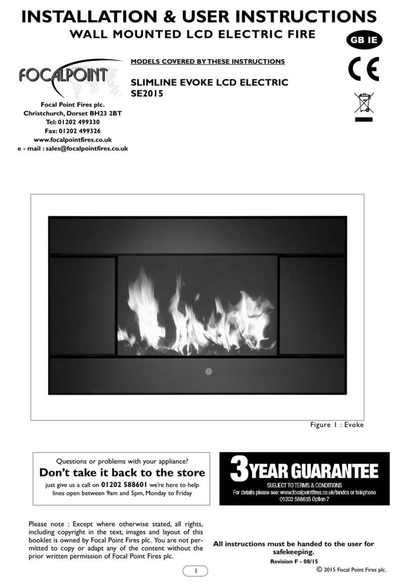
Focal Point SLIMLINE EVOKE Assembly Instructions

Focal Point
Focal Point LIBRA ELECTRIC EF451SLB Assembly Instructions

Focal Point
Focal Point ATHERSTONE SLATE ELECTRIC SUITE Assembly Instructions
Popular Indoor Fireplace manuals by other brands
barbas
barbas Evolux 100-45 Installation and maintenance manual

Amantii
Amantii SYM-B Series How To Fix
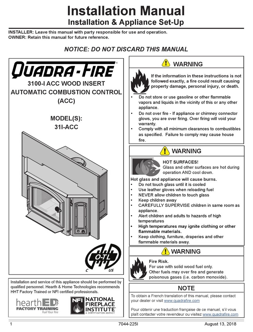
Quadra-Fire
Quadra-Fire 3100-I installation manual
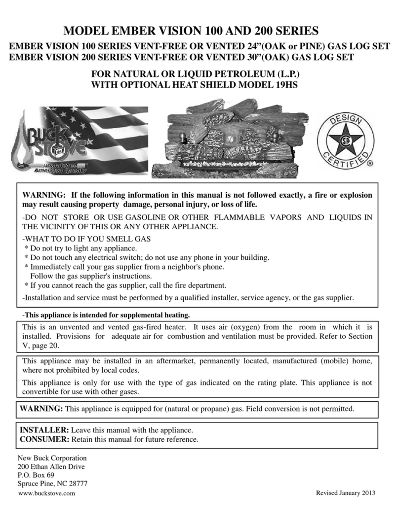
New Buck Corporation
New Buck Corporation EMBER VISION 100 SERIES installation instructions

Defro Home
Defro Home INTRA SLIM Series operating manual
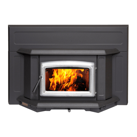
Pacific energy
Pacific energy SUPER INSERT DESIGN-E SPNE operating instructions
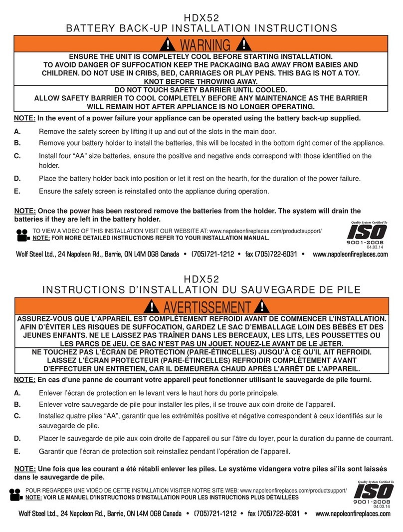
Napoleon
Napoleon HDX52 installation instructions
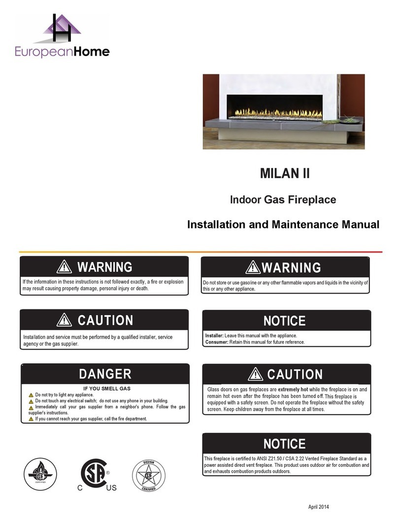
European Home
European Home MILAN II Installation and maintenance manual
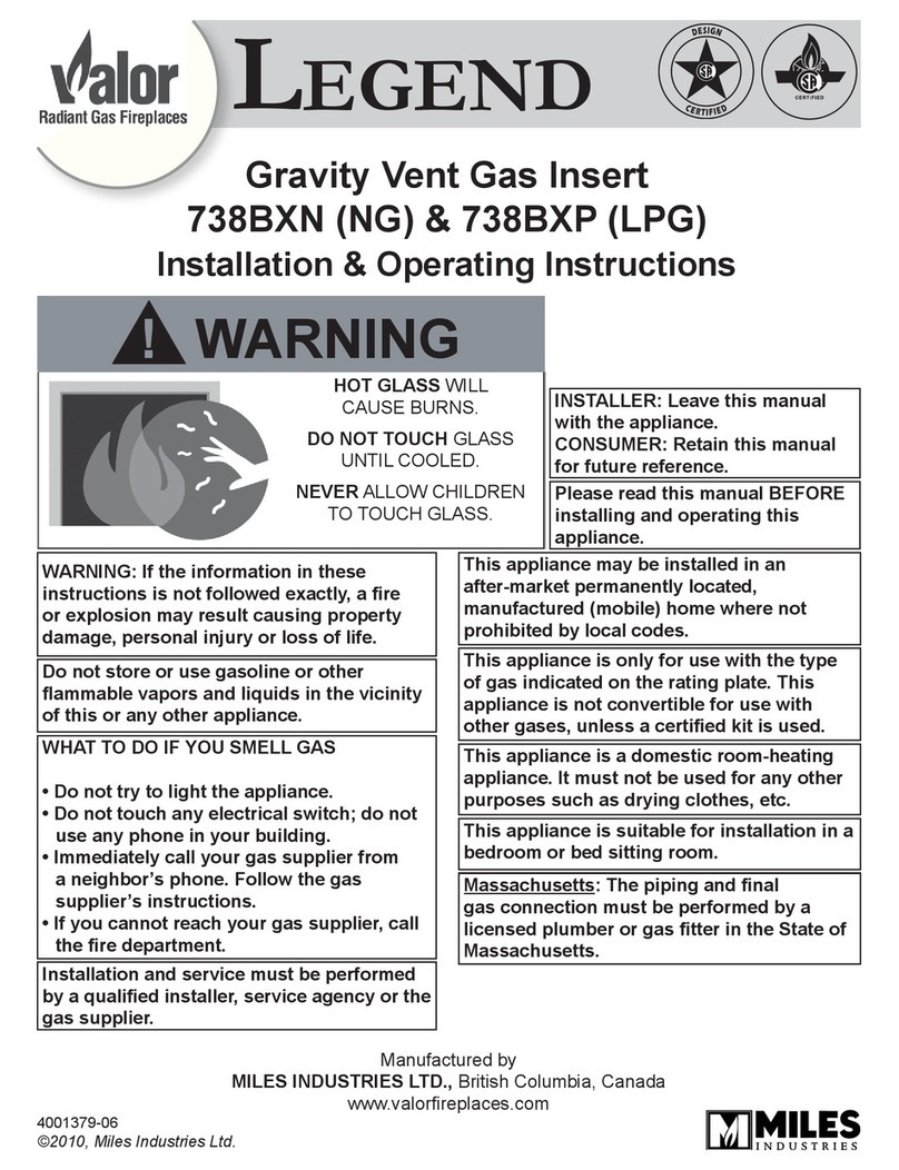
Legend
Legend 738BXN (NG) Installation & operating instructions
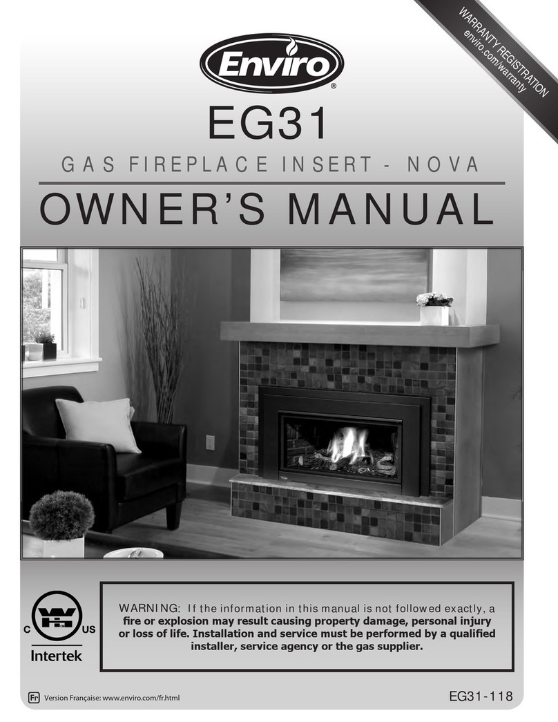
Enviro
Enviro EG31 Nova owner's manual
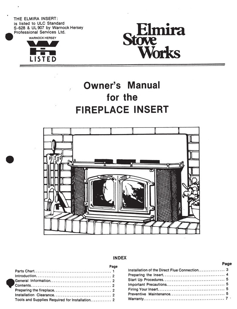
Elmira Stove Works
Elmira Stove Works Fireplace owner's manual

Napoleon
Napoleon NZ3000 Installation and operating instructions
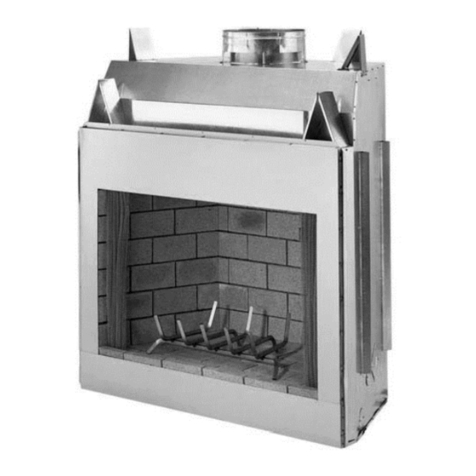
Mendota
Mendota SEABROOK D-30 Installation and operating instructions
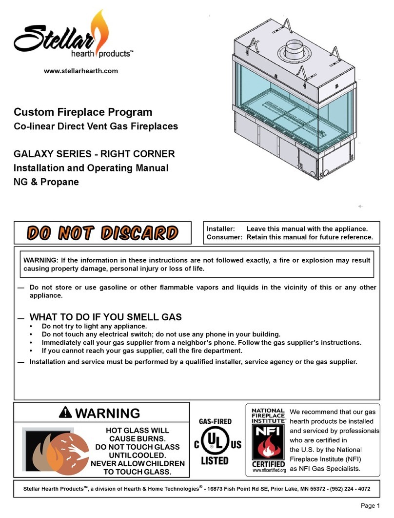
Stellar Hearth Products
Stellar Hearth Products GALAXY Series Installation and operating manual
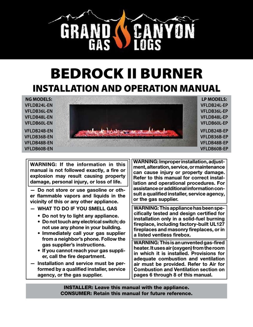
Grand Canyon Gas Logs
Grand Canyon Gas Logs BEDROCK II BURNER VFLDB24L-EN Installation and operation manual

Valor
Valor 1400IN Installation & owner's manual
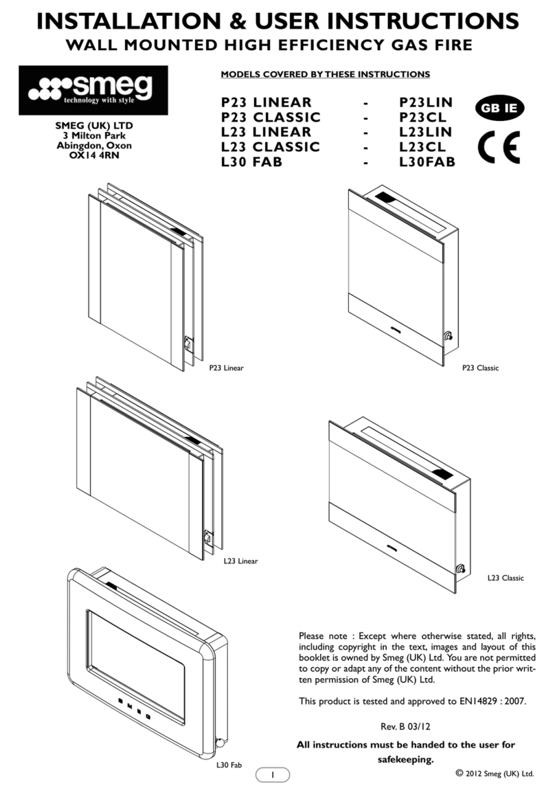
Smeg
Smeg P23 LINEAR Installation & user's instructions

Vermont Castings
Vermont Castings VE1263 Installation instructions and homeowner's manual

