FOG 444 9160 User manual
E 219 GB (991 9709)
Edition 1 : 01/2007
Installation - Operation
Maintenance - Spare Parts
Servicebook
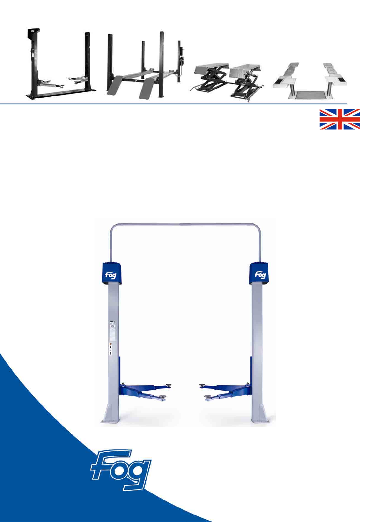
2-POST VEHICLE LIFT
444 9160 (3 T)
444 9180 (3 T)
442 9020 (3.5T)
English

444 9160 / 444 9180 / 442 9020
E 219 GB - Issue 1
2
Issue
F.F.B. reserves the right to modify the information contained in this manual at any time (non-contractual
document).
Despite the greatest care with which this document has been prepared, F.F.B. cannot be held
responsible, and may not be sued for any error or omission which may have crept into this publication.
All the updates of this manual are displayed below. The latest issues or additional copies of this manual
are available from F.F.B. S.A. Rue du Pré Neuf. 58440 Myennes FRANCE.
Minor changes are indicated by a thick line next to the modified text.
ISSUE PUBLICATION TEXT/ILLUSTRATIONMODIFIED
Number 1 01/2007 First issue.

444 9160 / 444 9180 / 442 9020
3
E 219 GB - Issue 1
Table of contents
TABLE OF CONTENTS
Description: Page:
1. Application range and appropriate use 4
2. SafetyInstructions 5
General Safety Instructions / Owner’s Responsibility 5
Basic Safety Measures during Normal Operation, Maintenance and Repair 6
ElectricalWork 6
Protection of the Environment 6
Practical Safety Instructions and Signs 7
General Safety Instructions for Vehicle Lifts 8
General Vehicle Lift Safety Instructions 9
Remaining Risks 10
3. ProductDescription 11
4. Technical Data 12
Datasheet 12
Lifting arms 16
5. Transport-Storage-Unpacking-Scope of Delivery 18
Informations in case of damages in transit 18
Notification of damages in transport 19
6. Foundation Plan and Power Supply (Customer) 20
Construction of foundation 21
Electrical connections, Air plug 22
Wiring in the concrete 23
7. Assembly and Installation 24
Area layout 24
Dowelling of the columns 24
Mounting of the lifting arms 27
Electricalconnections 28
Control platform 29
Adjustment of control platform 30
Mounting of housing 31
8. Handling and Conduct during Operation 32
Description of operating elements 32
Initial operation 33
9. Fault finding / problem solving 34
Emergency lowering at power failure 35
Emergency lowering with the service plug 35
Operating instructions – control of new vehicle lifts 36
10. Monitoring of Safety Devices 39
Carrying nut break protection 39
Carrying nut wear and tear test 39
Obstacle detection 39
11. Maintenance 40
12. Spare parts supply 41
13. Electrical diagrams 42
14. Spare parts 45
15. Service book 61
Guarantee 69

444 9160 / 444 9180 / 442 9020
E 219 GB - Issue 1
4
1. Application range and appropriate use
The 2-Post lift has been tested for functionality and longevity. It is most economical and safe. It is up to you to
make use of these advantages.
This is best achieved through correct handling, good maintenance and good care of the lift. Please read the
operating instructions carefully. It contains all necessary data and shows how easy it is to keep your lift in
good working order.
The lift is designed to lift motorised vehicles; it is not meant to transport persons. If the
lift is used in car body shops, i.e. in rooms where solvents are used, please be aware of
the danger of explosion. The standard engine is not protected against explosions.
The lift is exclusively designed for lifting passenger cars or vehicles where the total
weight is not above the maximum permitted carrying capacity of the lift and where
stipulated acceptance points lie within the acceptance area of the lift.
Your lift has been furnished with a safety device which guarantees safe operation when handled in
accordance with the instructions.
During installation and operation please pay attention to the functioning of the safety device and check this
after each fault incident.
Please make sure that a function test is carried out after each fault incident.
Your vehicle should only be maintained and repaired by manufacturer trained specialists who possess the
relevant certificate.
Only original spare parts should be used.
If other spare parts are used, the CE-conformity will be null and void.
According to the regulations about the operation of vehicle lifts, lifting gear must be subjected to a safety test
by an expert after one year at the latest.
This test must be entered into the test report book.
Please note, that only manufacturer trained specialists who are certified by the manufacturer as lift experts
can test your lift and confirm its good functioning.
Customer responsibilities
1. A site complying with the specifications in chapter 6 must be provided.
2. Ensure access to a protected electrical supply complying with CE regulations, and use a qualified
electrician to connect the lift to the electrical supply and check the safety of the electrical circuits.
3. Use fixing bolts of an appropriate length. See Assembly and Installation Chapter.
4. Any person assisting the installing technician must be familiar with the handling and health and safety
regulations.
5. An initial inspection must be carried out before commissioning the lift to comply with current legislation
(static and dynamic tests).
6. Means for marking out the danger zone must be provided.
7. Ensure that only competent persons operate and service the lift.
8. Keep this manual for the lift’s entire service life.

444 9160 / 444 9180 / 442 9020
5
E 219 GB - Issue 1
2. Safety Instructions
GENERAL SAFETY INSTRUCTIONS
Owner’s Responsibility:
The vehicle lift is constructed and built to legal standard and further technical specifications. It therefore
corresponds to current technology and gua rantees the highest degree of safety in operation.
Please note, that the machine is only safe in action when all necessary measures have been met. It is the
responsibility of the vehicle lift owner to plan and check that the regulations are adhered to..
The owner is responsible for the following safety aspects:
•The vehicle lift must only be used for its intended purpose.
•The vehicle lift must be kept in good functioning condition and especially the safety equipment
must be checked regularly to ensure that they are functioning reliably.
•Operating, maintenance and repair staff must be supplied with the necessary protective gear
and it is essential that this is worn.
•The operating instructions must be kept in a legible condition and must be available where the
machine is used.
•Only qualified and authorised personnel should operate, maintain and repair the machine.
•The personnel must be regularly informed about relevant industrial safety and environmental
issues and must know the operating instructions and the safety regulations contained therein.
•Any safety labels and warnings attached to the vehicle lift must not be re moved and must be
legible.

444 9160 / 444 9180 / 442 9020
E 219 GB - Issue 1
6
Basic Safety Measures during Normal Operation:
The vehicle lift may only be operated by authorised personnel who have received
specialist training who know the operating instructions and are able to adhere to them.
Before switching on the lift, the following must be checked and ensured:
•Only authorised persons may be present in the working area of the lift.
•It must be ensured that nobody can be injured when the lift is set in motion.
•Before each use, the lift must be checked for visible damages and it must be ensured that
it is only operated in good condition.
•Faults must immediately be reported to the responsible member of staff.
•Before starting to operate the machine it must be checked and secured that all safety
equipment is in good functioning order.
Inspection and maintenance intervals stipulated in the operating instructions must be
observed.
Basic Safety Measures during Maintenance and Repair:
Before maintenance or repair work is carried out, the working area of the lift must
be made inaccessible for unauthorised persons. A sign should show clearly that
maintenance or repair work is in progress!
Before maintenance or repair work is carried out, unplug the power supply or, if this is
not possible, switch off at the mains and secure it with a padlock. The key to this padlock
should be kept by the person who carries out the maintenance or repair work. If heavy
machine parts are to be exchanged, the load bearing equipment and buffer should be
in good condition.
Any lubricating, cooling or cleaning agents which might endanger the environment,
should be disposed of properly.
Electrical Work:
Repair work on the electrical system of the lift should only be carried out by a qualified
electrician.
Electrical installations should be checked regularly.
Loose connections should be tightened.
Damaged leads / cables must be exchanged immediately.
Keep housing of electrical installations closed at all times. Access is only per mitted
to authorised persons in charge of the key / tools.
Housing of electrical installations must never be cleaned with a hose pipe.
Protection of the Environment:
During all work with and on the vehicle lift the statutory regulations regarding the
avoidance of waste and proper waste disposal must be adhered to.
In particular during installation, repair and maintenance work, water contaminating
materials must not be allowed to seep into the soil or into the sewage system. These
include: - Grease and oils - Oils for hydraulic systems
- Cooling agents - Detergents containing solvents
Such materials must be kept, transported and collected in suitable containers and
disposed of.
444 9160 / 444 9180 / 442 9020
7
E 219 GB - Issue 1
Practical Safety Instructions and Signs:
The following operating instructions contain practical safety directions in order to draw attention to any
unavoidable risks which might occur while the vehicle lift is in operation. Such remaining risks en danger:
•people
•products
•the environment
The signs used in the operating instructions are there mainly to draw attention to the safety directions.
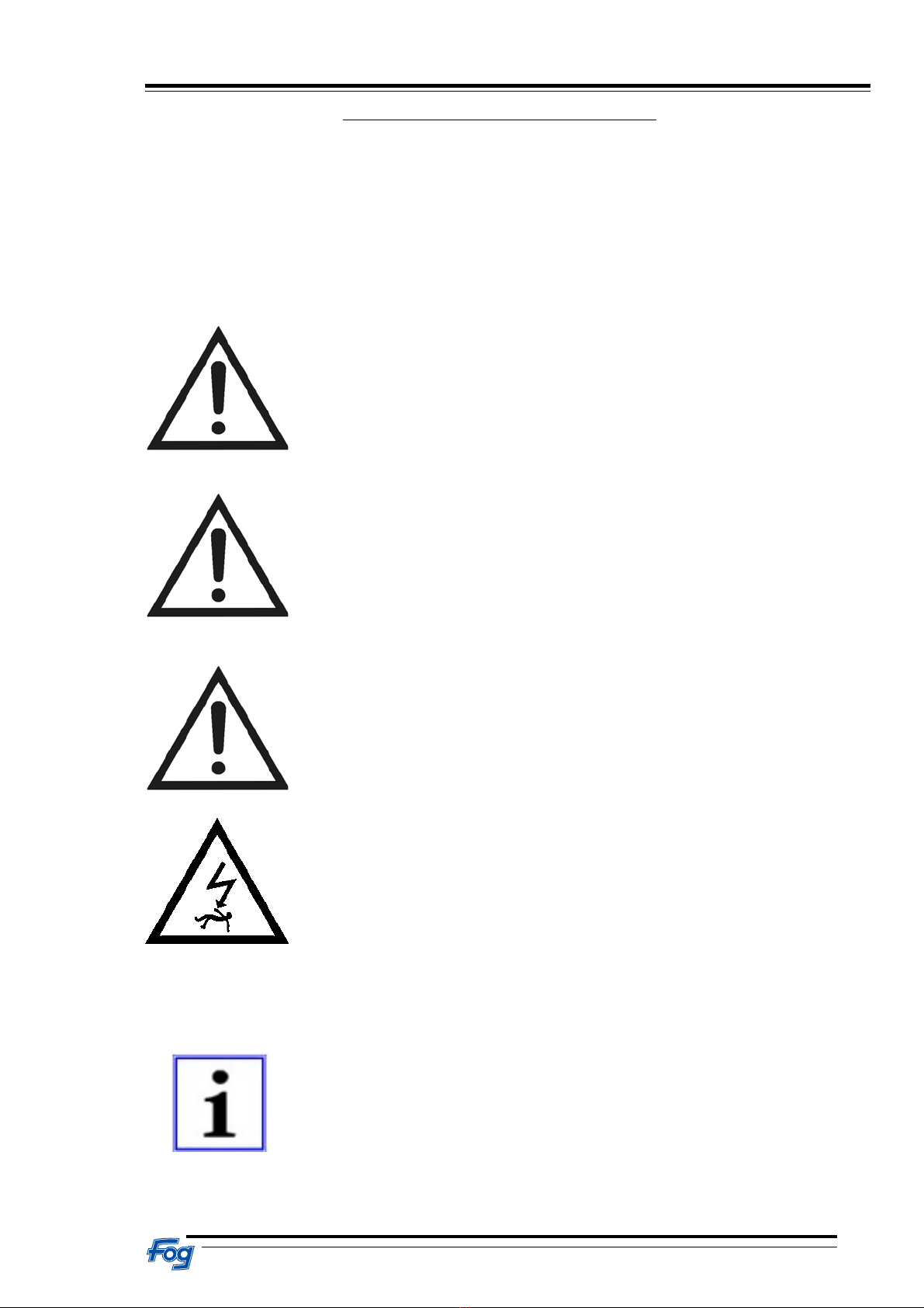
Danger - The sign points to danger for persons (fatal accidents or injuries)
Caution - This sign points to danger for machines, materials and the environment.
Danger – general sign
This sign is a reminder that the power supply to the housing must be switched off
and locked so that it is secured against accidental switching on.
The most important aim of the safety directions is to prevent injury to people.
The applied sign cannot replace the text of the safety directions. The text must always be read in full.
This sign does not relate to safety but gives information which should lead to a
better understanding of the machine proceses.
Danger
Caution
Information

444 9160 / 444 9180 / 442 9020
E 219 GB - Issue 1
8
General Safety Instructions for Vehicle Lifts:
The vehicle lift must only be used for lifting vehicles in accordance with the technical data.
Only trained personnel may operate the system.
Safety devices must not be replaced.
Necessary repair work may only be carried out by instructed customer service personnel.
Unauthorised alterations of the equipment render any liability by the manufacturer for any
resulting damages invalid.
Work on electrical installations may only be carried out by electricians.
The vehicle lift must not be operated in environments liable to explosions.

444 9160 / 444 9180 / 442 9020
9
E 219 GB - Issue 1
General Vehicle Lift Safety Instructions:
An uneven distribution of load on the front and back pick-up platforms should not exceed the listed
ratio of the types: 444 9160 and 444 9180 at a capacity of 3000 kg
3 to 2
442 9020 at a capacity of 3500 kg
2 to 1
The vehicle must always rest on all 4 supporting pads.
The vehicle must be picked up at the points stipulated by the manufacturer.
The vehicle and the lift must be observed during all vertical movements.
While the lift is operated, the danger area must be kept free. Travelling on or climingup on the
lift is not permitted. Persons under the age of 18 must not operate the lift.
The safety devices must not be changed in their position or function.
Repairs should only be carried out by authorised specialists.
The statutory accident prevention rules must be adhered to.
No work must be carried out on the vehicle during vertical movements.
The nominal load shown on the lift must not be exceed.
After a brief lifting of the vehicle it should be checked that all lifting arms are securely bolted.
If necessary, the vehicle should be lowered again and by a slight oscillating movement of the
lifting arm the bolt should slip into place.
During assembly and dismantling of vehicle units the eccentricity of the centre of gravity must
be taken into account.
Take care when vehicles are loaded! (other total weight and weight displacement)
If the safety instructions are not observed there is a
danger of injury!
Danger
444 9160 / 444 9180 / 442 9020
E 219 GB - Issue 1
10
Remaining Risks:
During vertical movements of the lift, no person is permitted to stand underneath a vehicle on
the lift or in the danger area. If this prohibition is not adhered to, there may be the danger of
injury. The operator must be expressly instructed to activate the up and down switch only if no
person is standing in the danger area.
The foot protection corresponds to statutory regulations, but this does not exclude all
imaginable possibilities of injury, but only those which are probable according to experience.
The operator must be instructed to activate the up and down switch only if no person is
standing in the danger area. Before each use, the protective device of the lift must be
checked for its perfect functionality.
If a vehicle has been mounted onto the lift according to instructions, there will be no danger of
accidents. If, however, the vehicle has not been mounted according to instructions, there is the
danger of injury. Special care must be taken with loaded vehicles or in cases of eccentricity of
centre of gravity through mounting or dismantling of heavy parts. The operator must be
instructed to check the mounting of the vehicle onto the lift before work commences.

444 9160 / 444 9180 / 442 9020
11
E 219 GB - Issue 1
3. Product Description
This lift consists mainly of two equal lift columns which are driven by an electric motor: the control column
with integrated base plate and the auxiliary column with an integrated base plate. There is no
mechanical connection between the lift columns. Each of the columns contains lifting spindles and a lifting
carriage with the load accepting devices.
The two electrical motors drive the lifting spindles by means of a sturdy and low-noise ribbed V-belt.
Integrated thermo-sensors in the motor coil winder act as an overload monitor.
The spindles house the various types of nuts: - supporting nuts with safety nuts - which are connected with the
two lifting carriages and, depending on the direction of the drive, carry out the up or down movements. The
two lifting carriages are guided by four gliding pieces in each column. The spindle supporting nut system
with carriages are maintenance free for one year if used as repair lift.
The necessary synchronisation of the carriage is guaranteed by an electronic synchronisation monitor. In the
event that the two carriages are not in parallel (for example, due to one-sided load, insufficient lubrication,
etc.) the synchronisation monitor will adjust the deviation within a distance of approx. 10 mm. This is done
by stopping the advanced carriage until the carriage which is lagging behind is at the same level again.
This process can be observed during a lifting action, possibly several times.
The drive is activated depending on the input by means of a key pad on the control panel; it is switched
on via an analogue path measuring counter in the upper and lower end position. After releasing the key
pad these return to “0” position automatically and the movement of the lift is stopped in each position of
the load uptake device.
The lift is fitted with safety devices, for example, the supporting nut break safety device which will transfer the
load to a free running safety nut in the case of a worn thread. During this process a mechanical safety system
is activated which will switch off the lift via the analogue path measuring counter and prevent a restart.
There is also the oscillating arm arrest which locks the lifting arms in their oscillating movement after a
lifting distance from the base position of approximately 100 mm in order to avoid that the supported
vehicle slips of the load bearing de vice.
The foot protection is activated via the analogue path measuring counter which stops the lowering of the
load automatically in the danger area (120 mm above the platform base). By pressing the key pad
“SENKEN” (down) again, the load carrier can be brought back into base position. This down-action in
the danger area will activate a warning signal tone.
The thermo-sensor in the drive motors causes the motors to switch off when they are too hot and after a
cooling-off time (of approx. 10-15 minutes) indicates that the lift can be used again.
An arch, which can be simply assembled, is placed above the control column to the auxiliary column, ,
serving as a safety channel for electrical cables (power supply, monitoring and control cables).
The lifting arms are, depending on the type, constructed resembling a single or double telescope which
can be adjusted to the required working length. The long single telescopic lifting arms in direction “up” at
the back and the short single or double telescopic lifting arms “up” in the front. This ensures that the doors
are free on both sides.
The vehicle to be raised is to be placed in such a way that the front door hinges are in the area of the lift
columns, so that a large door opening angle is created
The aim should be to direct the motor side of the vehicle towards the short oscillating arms (centre of
gravity of the vehicle should be at the centre of the lift if possible).

444 9160 / 444 9180 / 442 9020
E 219 GB - Issue 1
12
4. Technical Data
We reserve the right to alter the construction.
444 9160 444 9180 442 9020
Lifting arms: With short 2-part lifting arms
min: 650 mm
max: 1030 mm
................................
And long 2-part lifting arms
min: 870 mm
max: 1475 mm
With short 3-part lifting arms
min: 550 mm
max: 1070 mm
................................
And long 2-part lifting arms
min: 870 mm
max: 1475 mm
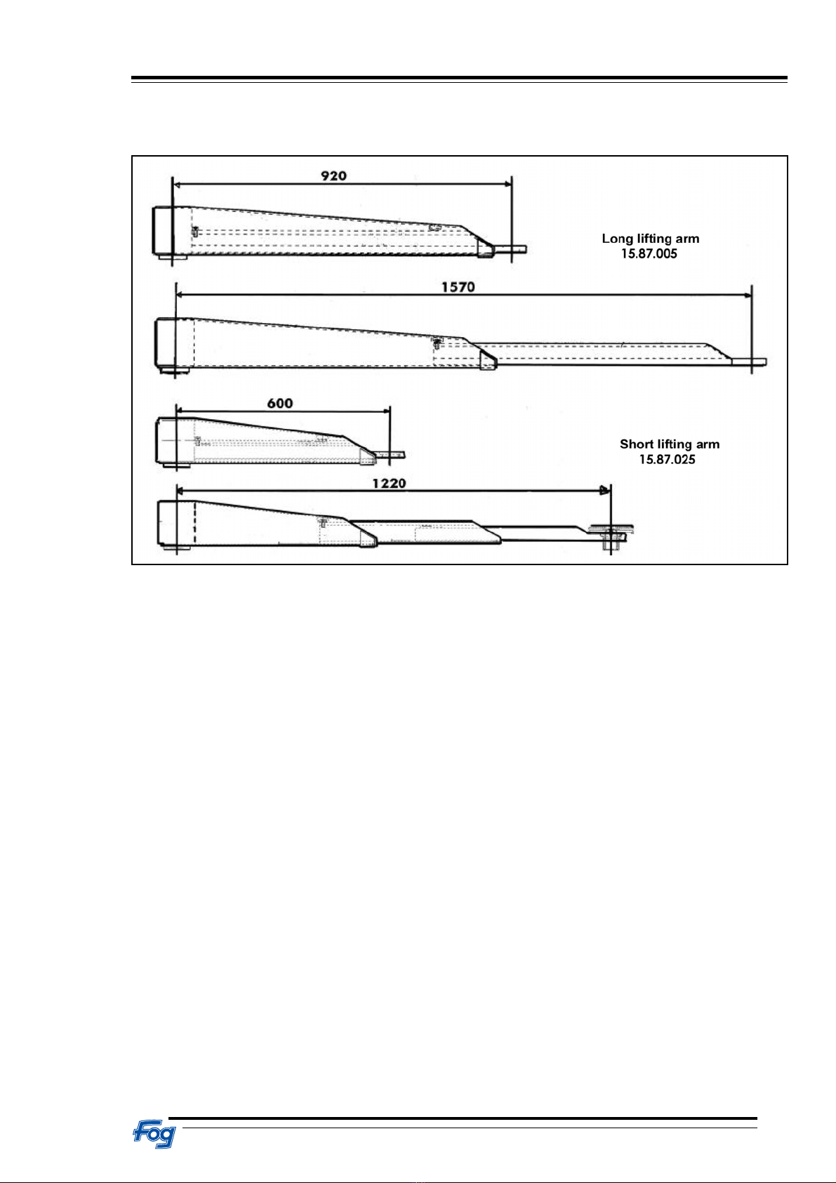
With short 3-part lifting arms
min: 600 mm
max: 1220 mm
................................
And long 2-part lifting arms
min: 920 mm
max: 1570 mm
Lifting arm
Locking device:
Automatic locking of lifting
arms
Automatic locking of lifting
arms
Automatic locking of lifting
arms
Supporting pads: Rotary plate d = 120 mm
Intake height:
min: 80 mm
max: 110 mm
Rotary plate d = 120 mm
Intake height:
min: 80 mm
max: 110 mm
Rotary plate d = 120 mm
Intake height:
min: 80 mm
max: 110 mm
Spindle lifting nut
system:
Electronic monitoring with
analogue counter
1 year maintenance free
Electronic monitoring with
analogue counter
1 year maintenance free
Electronic monitoring with
analogue counter
1 year maintenance free
Operating panel: 1 key pad on steering
column
1 key pad on steering
column,
1 additional key pad
2 sockets 230V,
1 air supply on auxiliary
column
1 key pad on steering
column,
1 additional key pad
2 sockets (1 socket
Switzerland) 230V, 1 air
supply on auxiliary column
Drive:
Power:
Connection value:
Fuse protection:
2 alternating current motors
2x2,4 KW
400V AC 50 Hz
3x20 A
2 alternating current motors
2x2,4 KW
400V AC 50 Hz
3x20 A
2 alternating current motors
2x3 KW
400V AC 50 Hz
3x25 A
Carrying
capacity:
1860 mm 1860 mm 1860 mm
Lifting time: 40sec 40sec 40sec
Weight:
Capacity: 3.000 kg 3.000 kg 3.500 kg
ED-operation: S3 S3 S3
Sound pressure
level:
70 dB(A) 70 dB(A) 70 dB(A)
444 9160 / 444 9180 / 442 9020
13
E 219 GB - Issue 1

444 9160 / 444 9180 / 442 9020
E 219 GB - Issue 1
14

444 9160 / 444 9180 / 442 9020
15
E 219 GB - Issue 1

444 9160 / 444 9180 / 442 9020
E 219 GB - Issue 1
16
Lifting arms for type 444 9160
Long lifting arm
15.87.001
Short lifting arm
15.87.020
Lifting arms for type 444 9180
Long lifting arm
15.87.001
Short lifting arm
15.87.023
444 9160 / 444 9180 / 442 9020
17
E 219 GB - Issue 1
Lifting arms for type 442 9020

444 9160 / 444 9180 / 442 9020
E 219 GB - Issue 1
18
5. Transport-Storage-Unpacking-Scope of Delivery
Transport and Storage:
The packed lift should only be lifted at the appropriate points.
Gripping the lift from below with a fork lift truck can lead to costly repairs.
The lift should not be stored outside.
The lift should be unpacked only one time arrived on its place of installation.
Unpacking
When the lift and the accompanying packages are unpacked, damages in transit should be noted and the
forwarding agent as well as F.F.B. should be informed immediately (see enclosed notification form).
The individual parts must be laid out in such a way that nothing can be lost when the packing material is
disposed of.
Despatch List
1x column complete control side
1x column complete opposite side
2x protective cap
2x lifting arm long complete
2x lifting arm short complete
1x U-profile for cross connection
1x box of accessories
IMPORTANT INFORMATION!
for our lift end customers in case of
DAMAGES IN TRANSIT
Delivery
Please check the goods immediately after arrival in the presence of the forwarding agent.
Should the goods show damages in transit, the forwarding agent must no be given a blank receipt.
If necessary, note the damage on the haulage documents.
Claim for damages
In order to ensure a quick and unproblematic handling of the damage, each damage in transit must be
reported to the F.F.B.-service partner immediately after the damage has been noticed.
The notification can be made by telephone, in writing or by fax / e-mail and must contain the following:
No. of assignment on the F.F.B.-delivery note and date of delivery
Type of lift and serial number
Exact description of the damage
(If necessary, use the back side of this information sheet).
Rectifying damages and settlement
The company F.F.B. can only deal with transport damages if a damage claim, as de scribed above,
has been made.
REPAIRS OR DELIVERIES OF SPARE PARTS AS WELL AS THE FINANCIAL SETTLEMENT
OF TRANSPORT DAMAGES ARE HANDLED BY YOUR F.F.B. SERVICE PARTNER.

444 9160 / 444 9180 / 442 9020
19
E 219 GB - Issue 1
NOTIFICATION OF DAMAGES IN TRANSPORT
On the lift Type: ______________________________________________________
Serial no.: ______________________________________________________
Delivered with Delivery note no.: ______________________________________________________
By Company: ______________________________________________________
Date: ______________________________________________________
The following damage was noticed On delivery
During unpacking
___________________________________________________________________________________________
___________________________________________________________________________________________
___________________________________________________________________________________________
___________________________________________________________________________________________
___________________________________________________________________________________________
___________________________________________________________________________________________
___________________________________________________________________________________________
___________________________________________________________________________________________
___________________________________________________________________________________________
(accurate description of the damage)
The packing was Damaged
Not damaged
Place/date Customer
444 9160 / 444 9180 / 442 9020
E 219 GB - Issue 1
20
6.FoundationPlanandPowerSupply(Customer)
Minimumrequirementrelatingtothebase:
The surface of the base must be level on all lifts. The foundation must comply with the general building
regulations (DIN 1054). For lifts which are installed outdoors, the foundation must be frost resistant. If the
lift is not to be installed on solid ground, an engineer engaged in statical calculations must examine each
case individually. The lifts are anchored with dowels.
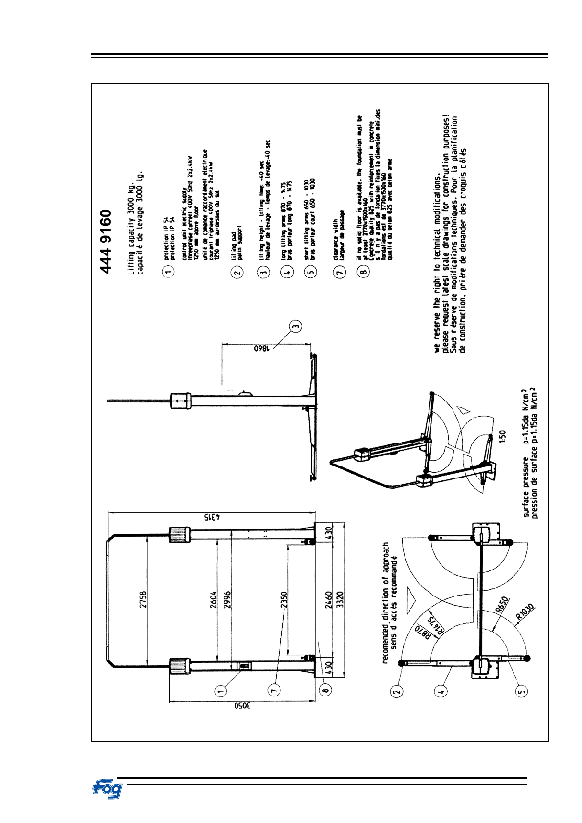
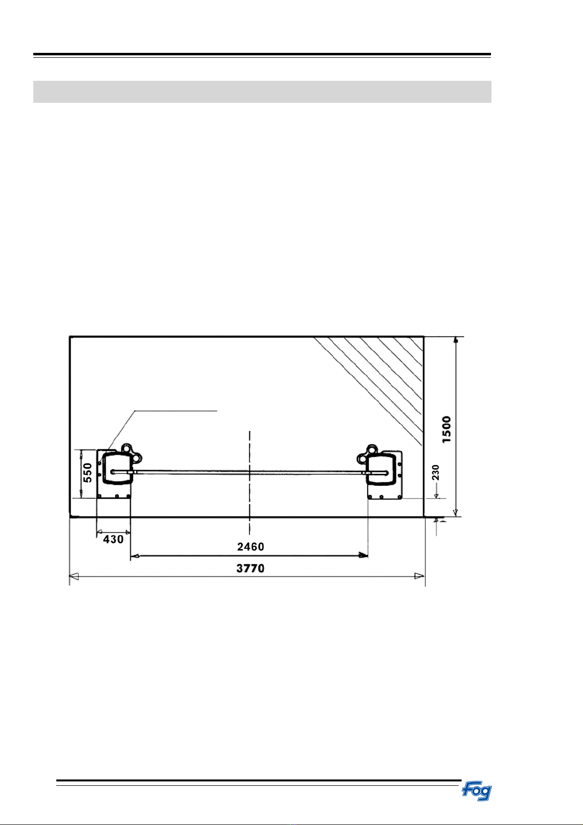
If no adequatel fixed foundation with the necessary concrete texture class is
available, then a foundation with the minimum size of 3770x1500x250 mm
of the concrete quality B25 with reinforcement must be created.
Surface pressing: p=1.15 daN/cm2 for Type 444 9160 / 444 9180
p=1.34 daN/cm2 for Type 442 9020
Drillholesfor
dowels
This manual suits for next models
2
Table of contents
Other FOG Lifting System manuals

Popular Lifting System manuals by other brands


Bishamon
Bishamon LV50WE Operation and service manual

Aqua Creek Products
Aqua Creek Products F-802SC2 quick start guide

Pro-Lift
Pro-Lift T-5350B Operating instructions & parts manual

MSA
MSA XTIRPA Instruction and safety manual

ABACO MACHINES
ABACO MACHINES ASB056M3 Operation manual

MAHA
MAHA HL CS Series operating instructions

Vestil
Vestil EHU-2 instruction manual

Blitz
Blitz MRG25-4 Operation & maintenance manual

EDER
EDER Power Climber 130 operating instructions

PLATFORM BASKET
PLATFORM BASKET SPIDER 18.90 PRO Use & maintenance manual

Sinoboom
Sinoboom AB16EJ Plus Maintenance manual

TRANZSPORTER
TRANZSPORTER TP250 Assembly instructions