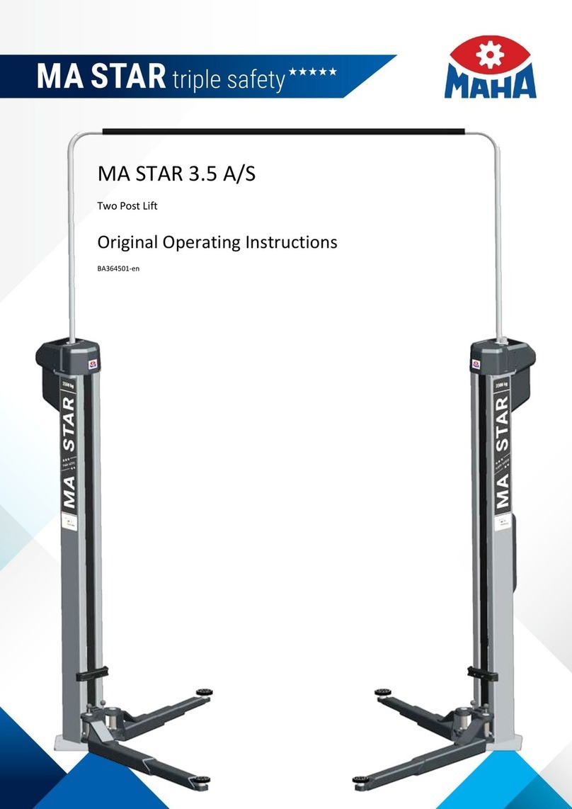
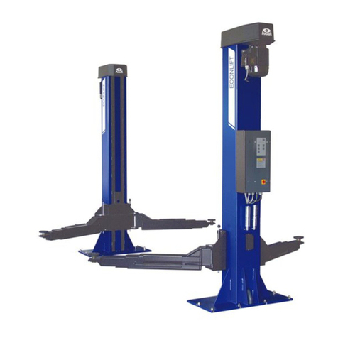
MAHA HL CS Series User manual

Fehler! Verwenden Sie die Registerkarte 'Start', um Name dem Text zuzuweisen, der hier angezeigt werden soll.Fehler! Verwenden Sie
die Registerkarte 'Start', um Name dem Text zuzuweisen, der hier angezeigt werden soll.Fehler! Verwenden Sie die Registerkarte
'Start', um Name dem Text zuzuweisen, der hier angezeigt werden soll.
HL CS 4.0
Two Post Lift
Original Operating Instructions
BA363901-en
Pos: 1 / Te chnisc he D okum entat ion/A lle G erä te/Tit eltex te/Tit eltext : HL CS 4. 0 - Al le Type n @ 29\mod_1347617265596_0.docx@ 1654075@ @ 1
HL CS 4.0 L
HL CS 4.0
HL CS 4.0 H
Pos: 2 / -----F or m at---- -/MAN UEL LE R UM B RUCH Seite numb r uc h @ 0\mod _ 11 344 03 577 6 87_ 0.d ocx @ 1 27 7 @ @ 1

2
BA363901-en
Pos: 3 / Te chnisc he D okum entat ion/Pap ierkor b/F orm at/In haltsver ze ichnis - 2 E b e nen @ 4 3\mod_1448887680115_75.docx @ 2352724@ @ 1
Contents
1
Safety.................................................................................................................. 5
1.1 Introduction..............................................................................................................5
1.2 Symbols...................................................................................................................5
1.3 Intended Use ...........................................................................................................5
1.4 Inappropriate Use.....................................................................................................5
1.5 Safety Instructions for Commissioning......................................................................5
1.6 Safety Instructions for Operation...............................................................................6
1.7 Safety Instructions for Servicing................................................................................6
1.8 Safety Instructions for Handling Hydraulic Fluid.........................................................7
1.9 What to Do in the Event of Defects or Malfunctions ..................................................7
1.10 What to Do in the Event of an Accident ....................................................................7
1.11 Safety Features ........................................................................................................8
2
Description .......................................................................................................... 9
2.1 General Information..................................................................................................9
2.2 Specifications...........................................................................................................9
3
Transport and Storage ....................................................................................... 11
4
Installation and Initial Operation........................................................................... 12
5
Operation .......................................................................................................... 12
5.1 Requirements on the Operator ...............................................................................12
5.2 Main Switch ...........................................................................................................12
5.3 Controls.................................................................................................................13
5.4 Preparations...........................................................................................................14
5.5 Raising...................................................................................................................14
5.6 Vehicle in Raised Position.......................................................................................14
5.7 Lowering................................................................................................................15
5.8 Manual Lowering....................................................................................................16
6
Maintenance...................................................................................................... 17
6.1 Annual Inspection...................................................................................................17
6.2 Maintenance Schedule...........................................................................................18
6.3 Care Instructions....................................................................................................18
6.4 Checking the Fluid Level.........................................................................................19
6.5 Greasing Points......................................................................................................20
6.6 Troubleshooting .....................................................................................................21
6.7 Spare Parts............................................................................................................21
7
Service Lifetime.................................................................................................. 22
3
BA363901-en
8
Dismantling........................................................................................................ 22
9
Disposal ............................................................................................................ 22
10
Contents of the Declaration of Conformity ........................................................... 22
11
Company Information......................................................................................... 23
Pos: 4 / -----F or m at---- -/MAN UEL LE R UM B RUCH Seite numb r uc h @ 0\mod _ 11 344 03 577 6 87_ 0.d ocx @ 1 27 7 @ @ 1

4
BA363901-en
Pos: 5 / -----F or m at---- -/MAN UEL LE R UM B RUCH Seite numb r uc h @ 0\mod _ 11 344 03 577 6 87_ 0.d ocx @ 1 27 7 @ @ 1

5
BA363901-en
Pos: 6 / Te chnisc he D okum entat ion/A lle G erä te/Üb erschr ifte n/Übers chr iften 1/ S/ Überschr ift 1: Sich erhei t @ 6\mod_1174482399906_75.docx@ 76962@ 1 @ 1
1
Safety
Pos: 7 / Te chnisc he D okum entat ion/A lle G erä te/Üb erschr ifte n/Übers chr iften 1 .1/E/ Übersc hrif t 1. 1: E inführ u ng @ 6\mod_1174482219062_75.docx@ 76793 @ 2 @ 1
1.1
Introduction
Pos: 8 / Te chn isc he Dokum en tat i on/A ll e Ger ä te/I n hal te/S ic her he it/I n ha lt: E inf ühr u ng Sicher hei t_ 12p t @2 5\mod_1324455248318_75.docx @ 1138886@ @ 1
Thoroughly read this manual before operating the equipment and comply with the
instructions. Always display the manual in a conspicuous location.
Personal injury and property damage incurred due to non-compliance with these
safety instructions are not covered by the product liability regulations.
Pos: 9 / Te chnisc he D okum entat ion/A lle G erä te/Üb erschr ifte n/Übers chr iften 1 .1/S/ Über schri ft 1. 1: Sy mbo le @ 6\mod_1174482270875_75.docx@ 76865@ 2 @ 1
1.2
Symbols
Pos: 10 /Techn ische Dokume ntation/Al le Geräte/Inh alte/Sicher heit/Inhal t: Symbole Sicher heit_12pt @ 2 5\mod_1324456650897_75.docx@ 1139046@ @ 1
Important safety instructions. Failure to comply with instructions could result in
personal injury or property damage.
Important information.
Pos: 1 1 / Techn ische Dokument atio n/Alle Geräte/Über sc hriften/ Über schri ften 1.1/B/ Überschr ift 1.1: Bes timm ungsg emä ßer G ebrau ch @ 6\mod _1176 73402 2203_ 75.doc x @ 8874 6 @ 2 @ 1
1.3
Intended Use
Pos: 1 2 / Techn ische Dokument atio n/Hebet ech nik/- A r ch iv -/ 00 H ebet echni k -A lle /I n ha lte/ I nh a lt : Bestim m u ngs gem äßer G ebr auc h H BZ _12p t @ 29\mod_1351147628024_75.docx@ 1668694@ @ 1
•This lift shall be used exclusively for the safe lifting of motor vehicles. Observe
the rated load capacity and load distribution.
•The lift shall not be modified without the express written consent of the manu-
facturer. In case of non-compliance the declaration of conformity becomes
void.
Pos: 1 3 / Techn ische Dokument atio n/Alle Geräte/Über sc hriften/ Über schri ften 1.1/B/ Überschr ift 1.1: Bes timm ungsw idr iger Geb rauc h @ 18\m od_1255530265027_75.docx@ 471571 @ 2@ 1
1.4
Inappropriate Use
Pos: 1 4 / Techn ische Dokument atio n/Hebet ech nik/- A r ch iv -/ 00 H ebet echni k -Al le/In ha lte/I nha lt: Bestimmungsw id ri ger Gebr a uch H BZ_ 12p t @ 26\mod_1325512462855_75.docx @ 1143595@ @1
Any use other than described is inappropriate, for example:
•Climbing on the lift supports
•Transporting persons on the lift supports
•Usage as mobile work platform or for other lifting operations
Pos: 1 5 / Techn ische Dokument atio n/Alle Geräte/Über sc hriften/ Übe rs chri fte n 1.1/S/ Über sc hr if t 1.1: S ic her he its vor schr ift en f ür d i e I nbe tr ieb nahm e @6\m od_1174482269156_75.docx@ 76838 @ 2 @ 1
1.5
Safety Instructions for Commissioning
Pos: 1 6 / Techn ische Dokument atio n/Hebet ech nik/- A r ch iv -/ 00 H ebet echni k -A lle /I n ha lte/ I nha lt : S ic her he itsv ors chri fte n f ür die Inb e trieb n ahm e H BZ _ 12p t @4 7\mod_1483524035338_75.docx @ 2804458@ @ 1
•The lift shall be installed and commissioned by authorised service personnel on-
ly.
•Use personal protective equipment.
•All safety features must be checked for proper function at commissioning.
•The control desk (if present) shall not be installed in the danger zone of the lift.

6
BA363901-en
•The standard lift version shall not be installed and commissioned in hazardous
locations, outdoors, in moist rooms (e.g. car wash) or outside a temperature
range of 5…40 °C (41…104 °F).
Pos: 1 7 / Techn ische Dokument atio n/Alle Geräte/Über sc hriften/ Über schri ften 1.1/S/Über sc hrift 1.1: Sic herhe itsvor schr iften f ür d en B etri eb @ 6\mod_1174482268953_75.docx@ 7 6826 @ 2 @ 1
1.6
Safety Instructions for Operation
Pos: 1 8 / Techn ische Dokument atio n/Hebet ech nik/- A r ch iv -/ 36 Säule n -Heb ebühn en/ 000 1 Säulen-H ebeb ühnen Alle/I nhalt e/Inh al t: S ic herh ei tsvors chr ift en für d e n Betr ieb Säulen-H BZ_12pt@ 46\mod_ 14 812 83 829688_75.docx @ 2797291@ @1
•Use personal protective equipment.
•Operation of the lift is permitted only with all protective covers (motor, spindle,
cylinder cover) correctly installed and undamaged.
•Drive on the lift only when it is in bottom position.
•Ensure an unobstructed movement of lift and vehicle.
•After raising the vehicle briefly, stop and check the lift supports for secure con-
tact with the vehicle.
•Make sure the vehicle doors are closed during raising and lowering cycles.
•Closely watch lift and vehicle during raising and lowering cycles.
•Do not allow anyone to stay in lift area during raising and lowering cycles.
•Do not allow anyone to climb on lift or inside raised vehicle.
•Comply with the applicable accident prevention regulations.
•Do not exceed the rated load capacity as indicated on the lift nameplate.
•Only use the vehicle manufacturer's recommended lift points.
•Do not use the lift for transporting persons.
•Lifts with runways: After positioning the vehicle on the lift secure it against roll-
off.
•Keep lift and vehicle free of tools and parts.
•Lifts with support arms: Use caution when removing or installing heavy compo-
nents. Center-of-gravity displacement may occur. Secure the vehicle using
lashing straps.
•Keep the lift and lift area clean. Slip hazard on oily surface!
•The main switch serves as emergency switch. In case of emergency turn it to
position "0".
•Protect all parts of the electrical equipment from humidity.
•Protect the lift against unauthorized usage by padlocking the main switch.
•Use caution with operating vehicle engines. Danger of poisoning!
Pos: 1 9 / Techn ische Dokument atio n/Alle Geräte/Über sc hriften/ Über schri ften 1.1/S/Über sc hrift 1.1: Sic herhe itsvor schr iften f ür Ser vicearb eiten @ 6\mod_1174482270640_75.docx @ 76850@ 2 @ 1
1.7
Safety Instructions for Servicing
Pos: 2 0 / Techn ische Dokument atio n/Hebet ech nik/- A r ch iv -/ 00 H ebet echni k -Al le/ In ha lte/I nha lt: S ic her he itsv ors chr ifte n f ür Servi cear be ite n H BZ_1 2p t @ 46\mod_1481283945452_75.docx @ 2797338 @ @ 1
•Use personal protective equipment.
•Service work must be done by authorized service technicians.
•Turn off and padlock the main switch before doing any repair, maintenance or
setup work.

7
BA363901-en
•The system must be unpressurized during maintenance work.
•Work on pulse generators or proximity switches must be done by authorized
service technicians.
•Work on the electrical equipment must be done by service technicians or quali-
fied electricians.
•Ensure that ecologically harmful substances are disposed of in accordance with
the appropriate regulations.
•Do not use high pressure or steam jet cleaners. Do not use caustic cleaning
agents.
•The lift's safety devices must be set by authorized service technicians.
•Do not replace or override the safety devices.
Pos: 21 /Techn ische Dokument ation/Alle Ger äte/Über sc h rif te n/ Üb er sc hri ft e n 1. 1/ S/ Üb ers c hr if t 1.1: S ic h erh e its v ors chr ift en f ü r d en Umga n g m it H y dr au lik öl @ 1 6\m od_1 24660 77295 23_75.d ocx @ 4 01284 @ 2 @ 1
1.8
Safety Instructions for Handling Hydraulic Fluid
Pos: 2 2 / Techn ische Dokument atio n/Alle Geräte/I nhalte/ Sich erhe it/In halt: Si cher heitsvor sc hriften für de n Umg ang m it H ydr aul iköl_ 12p t @ 2 5\mod_1324456399127_75.docx @ 1139012@ @1
•Neutralize hydraulic fluid spills with binder.
•Remove contaminated clothing immediately.
•Inhalation: If symptoms persist, seek medical treatment.
•Skin contact: Wash skin immediately with soap and water. If skin irritation per-
sists, seek immediate medical advice.
•Eye contact: Rinse thoroughly with water and seek medical advice.
•Ingestion: Do not induce vomiting. Seek immediate medical attention.
Pos: 2 3 / Techn ische Dokument atio n/Alle Geräte/Über sc hriften/ Über schri ften 1.1/V/Über sc hrift 1 .1: Ver hal ten im Störfall @ 6\mod_1178097008375_75.docx @ 90829@ 2 @ 1
1.9
What to Do in the Event of Defects or Malfunctions
Pos: 2 4 / Tec hnische Dokume ntation/H ebetechni k/-A r ch iv -/ 00 H ebet ech nik -A lle /I n ha lte/ I nha lt : V er h al ten im St ör fa ll H B Z_ 12p t @ 2 6\mod_1325513682583_75.docx@ 1143723@ @1
•In case of defects or malfunctions such as uncontrolled lift movement or defor-
mation of the superstructure, support or lower the lift immediately.
•Turn off the main switch and secure it against unauthorized usage. Contact
service.
Pos: 2 5 / Techn ische Dokument atio n/Alle Geräte/Über sc hriften/ Über schri ften 1.1/V/Über sc hrift 1 .1: Ver hal ten bei Unfällen@ 19\mod _126 71772 45337_ 75.do cx @ 794 600 @ 2 @ 1
1.10
What to Do in the Event of an Accident
Pos: 26 /Techn ische Dokume ntation/Al le Geräte/Inh alte/Sicher heit/Inhal t: Verhalten bei U nfällen_12p t @3 4\mod_1381128863435_75.docx@ 1837175@ @ 1
•The injured person is to be removed from the danger area. Find out where
dressing and bandages are kept. Seek first-aid.
•Provide first-aid (stop bleeding, immobilise injured limbs), report the accident
and seal off the accident site.
•Immediately report any accident to your supervisor. Make sure a record is kept
of every occasion first-aid is provided, e.g. in an accident book.
•Remain calm and answer any questions that may arise.
Pos: 2 7 /----- Form a t-----/ MA N UE L LE R UM BR UC H S e i ten um b r uch @ 0\m od_1134403577687_0.doc x @ 1277 @ @ 1

8
BA363901-en
Pos: 2 8 / Tec hn isch e Dokume nt at ion/ Al le G erä te /Üb ers c hrift en/ Übe rs chri fte n 1.1/S/ Über sc hr if t 1.1: S ic herhe it se inr ic ht un gen @ 6\m od_11 74483 32476 5_7 5.docx @ 77 103 @ 2 @ 1
1.11
Safety Features
Pos: 2 9 / Techn ische Dokument atio n/Hebet ech nik/- A r ch iv -/ 36 Säule n -Heb eb ü hne n/ 39 01 H L C S 4.0/ BA/ In hal t: 3 63 9 S iche rh ei tse inr i chtun ge n @ 28\m od_1333540519147_75.docx@ 1578663@ @ 1
Dead Man's Type Control
The operator is required to push and hold the control buttons to raise or lower the
lift.
Synchronization
Synchronized operation of the carriages is achieved through a wire-actuated en-
coder system.
Anti-Collision Switch
A limit switch actuated via a tube prevents the vehicle roof from colliding with the
overhead cable tray of the lift.
Pinch Point Protection
During lowering cycles the lift automatically stops shortly before reaching bottom
position.
To lower the lift completely, the "Lower" button must be released and the Button
"Lower to bottom position (CE STOP)" must be pushed. Lift travel to the lower lim-
it stop is accompanied by an audible signal.
Automatic Arm Restraint
The support arm restraint locks automatically when the lift is raised. The arms
cannot be swivelled while in the engaged position.
Velocity Fuse
The hydraulic cylinders are equipped with velocity fuses. These respond in the
event of a sudden pressure drop in the hydraulic system and prevent the lift from
uncontrolled lowering motions.
Pressure Relief Valvel
The hydraulic system is equipped with a pressure relief valve.
Pos: 3 0 /----- Form a t-----/ MA N UE L LE R UM BR UC H S e i ten um b r uch @ 0\m od_1134403577687_0.docx @ 1277@ @ 1

9
BA363901-en
Pos: 3 1 / Techn ische Dokument atio n/Alle Geräte/Über sc hriften/ Über schri ften 1/B/Über schri ft 1: Bes chr eibun g @ 6\mod_1174482271453_75.docx@ 76889 @1 @ 1
2
Description
Pos: 3 2 / Techn ische Dokument atio n/Alle Geräte/Über sc hriften/ Über schri ften 1.1/A/Über sc hrift 1.1: All gemei nes @ 6\mod_1182865005781_75.docx@ 97736@ 2 @ 1
2.1
General Information
Pos: 3 3 / Techn ische Dokument atio n/Hebet ech nik/- A r ch iv -/ 36 Säu le n-Heb ebü hnen/ 390 1 HL C S 4 .0/BA/ Inhal t: 3 639 Bes chre ibun g A llgem eines @ 28\mod_1333552940279_75.docx@ 1579199 @ @ 1
This lift model is equipped with four telescopic support arms. The drive system
consists of two hydraulic cylinders with a hydraulic power unit. The lift is operated
via an electric dead man's type control using pushbuttons, synchronization is
achieved through a wire rope synchronization system.
Pos: 3 4 / Techn ische Dokument atio n/Alle Geräte/Über sc hriften/ Über schri ften 1.1/T/Üb erschr ift 1.1: Tech nis che D aten @ 7\mod_1184075526343_75.docx @ 99711@ 2 @ 1
2.2
Specifications
Pos: 3 5 / Techn ische Dokument atio n/Hebet ech nik/- A r ch iv -/ 36 Säule n -Heb eb ü hne n/ 39 01 H L C S 4.0/ BA/ In hal t: 3 63 9 Te ch nisc he Date n ( Bild er ) @2 8\mod _ 1 332 23 8303125_0.docx@ 1567509@ @ 1

10
BA363901-en
Pos: 3 6 / Techn ische Dokument atio n/Hebet ech nik/- A r ch iv -/ 36 Säule n -He be bü hn e n/ 39 0 1 H L CS 4.0/ BA/ I n hal t: 3639 Tech nis c he Date n ( Ta be ll e) @ 33\m od_1 37412 75595 07_75. docx @ 1 80951 9 @ @ 1
HL CS 4.0 L
HL CS 4.0
HL CS 4.0 H
Overall height HG 3625 mm 4178 mm 4778 mm
Clear height HL 3545 mm 4100 mm 4700 mm
Full travel HW 1703 mm 1803 mm 1803 mm
Lifting height max. HO 1823 mm 1923 mm 1923 mm
Lifting height min. HU 110 mm
Adjustm. range of support discs HT 85…120 mm
Adjustm. range of supp. arm LT 585…1150 mm
Adjustm. range of supp. arm LL 917…1505 mm
Inside columns BL 2800 mm
Outside columns BA 3290 mm
Baseplate projection BP 98 mm
Outside baseplates BG 3486 mm

11
BA363901-en
HL CS 4.0 L
HL CS 4.0
HL CS 4.0 H
Inside baseplates BGi 2766 mm
Drive-through width max. BH 2450 mm
Load capacity 4000 kg
Load distribution front:rear min. 1:3 / max. 3:1
Net weight 700 kg
Motor power 2,2 kW
Fuse (slow breaker) 16 A
Supply voltage 3 x 400 V
Raising/Lowering time (load-dep.) 45 s
Ambient temperature +5…+40 °C
Noise emission < 70 dB(A)
Pos: 3 7 / Techn ische Dokument atio n/Alle Geräte/Über sc hriften/ Über schri ften 1/T/Über schri ft 1: Tr ansp ort und Lageru ng @2 0\mod_1268732488860_75.docx @ 826153@ 1 @ 1
3
Transport and Storage
Pos: 3 8 / Technische Dokument ation/Al le Geräte/Inh alte/Inhal t: Transport und Lageru ng_12pt @ 26\mod_1324468980166_75.docx@ 1141285@ @ 1
Check package to ensure it is complete, in accordance with the order
confirmation. Report any transport damage to the carrier immediately.
During loading, unloading and transport always use suitable lifting equipment,
material handling equipment (e.g. cranes, forklifts, etc.) and the right load handling
attachments and slings. Always ensure that the parts to be transported are
suspended or loaded properly so that they cannot fall, taking into account size,
weight and the centre of gravity.
Store the packages in a covered area, protected from direct sunlight, at a low
humidity and with temperatures between 0...+40 °C (32…104 °F). Do not stack
packages.
When unpacking, take care to avoid any possibility of injury or damage. Keep at a
safe distance when opening the package strapping, do not allow any parts to fall
out.
Pos: 3 9 /----- Form a t-----/ MA N UE L LE R UM BR UC H S e i ten um b r uch @ 0\m od _1134403577687_0.docx@ 1277 @ @1

12
BA363901-en
Pos: 4 0 / Techn ische Dokument atio n/Alle Geräte/Über sc hriften/ Über schri ften 1/M/Übers chr ift 1 : M ontag e und Erstinbe triebn ahm e @ 18\mod_1255417443299_75.docx @ 463797@ 1 @ 1
4
Installation and Initial Operation
Pos: 4 1 / Technische Do kumentat ion/Alle Geräte/ Inhalte/Inh alt:M ontage u ndE rstinbetrieb nahme_12p t @ 26\mod_1324468562877_75.docx@ 1141153@ @ 1
Installation and initial operation of the equipment may be done only by authorized
and trained service technicians provided by the manufacturer, licensed dealers or
service partners.
Pos: 4 2 /----- Form a t-----/ MAN UE L LER UMB RUC H Zeile ns c ha lt un g @ 7\mod _11 95138 96573 1_0.d ocx @ 132 177 @ @ 1
Pos: 4 3 / Techn ische Dokument atio n/Alle Geräte/Über sc hriften/ Über schri ften 1/B/Über schri ft 1: Bed ie nu ng @ 6\mod_1174482271218_75.docx@ 76877 @1 @ 1
5
Operation
Pos: 4 4 / Techn ische Dokument atio n/Papi erkorb /Über sc hriften/ Über schrif t 1. 1: Anf ord erun gen a n d en Bediener @ 18\mod_1255531954990_75.docx @ 471737@ 2 @ 1
5.1
Requirements on the Operator
Pos: 45 /Techn ische Dokume ntation/Al le Geräte/Inh alte/Warnu ng!/Inhalt: W arnung - Anf orderungen an d en Bediener_1 2pt @ 26\mod_1324464226462_75.docx @ 1140361@ @1
All persons employed in the operation, maintenance, installation, removal and dis-
posal of the device must
•be at least 18 years old,
•be trained and instructed in writing,
•have read and understood this manual
•be on record as having been instructed in safety guidelines.
Pos: 46 /Techn ische Dokument ation/Alle Ger äte/ Übersc hrift en/ Überschr ifte n 1. 1/H/ Überschr ift 1.1: Haup tsch alter @ 6\m od_11 77592 8583 12_75.d ocx @ 90 635 @ 2 @ 1
5.2
Main Switch
Pos: 4 7 / Techn ische Dokument atio n/Hebet ech nik/- A r ch iv -/ 00 H ebet echni k -A lle /I n ha lte/ I nha lt : H a up tsc ha lte r m it Not-Aus -Funkt ion H BZ _12p t @ 26\mod_1325575201603_75.docx @ 1144333@ @1
The main switch is used as emergency switch. In case of emergency turn it to po-
sition 0.
•Main switch in position 0: Power supply is interrupted
•Main switch in position 1: Lift is ready for operation
•When in position 0, the main switch can be protected against
tampering by means of a padlock.
Pos: 4 8 /----- Form a t-----/ MA N UE L LE R UM BR UC H S e i ten um b r uch @ 0\m od_1134403577687_0.docx @ 127 7 @ @ 1

13
BA363901-en
Pos: 4 9 / Techn ische Dokument atio n/Alle Geräte/Über sc hriften/ Über schri ften 1.1/B/ Überschr ift 1.1: Bed ienel emen te @ 1 3\mod _123 79750 99177_ 75.d ocx @ 35 9008 @ 2 @ 1
5.3
Controls
Pos: 5 0 / Techn ische Dokument atio n/Hebet ech nik/- A r ch iv -/ 36 Säu le n-Heb ebü hnen/ 390 1 HL C S 4 .0/BA/ Inhal t: 3 639 Bed ien elemen te ( Bild) @ 29\mod_1347608791654_0.docx@ 1653663@ @ 1
Pos: 5 1 / Techn ische Dokument atio n/Hebet ech nik/- A r ch iv -/ 36 Säule n -Heb ebühn en/ 390 1 HL CS 4.0/BA/ In halt: 3 639 Bed ien elemen te ( Tex t) @ 29\mod_1347611147025_75.docx@ 1653708@ @ 1
A: RAISE / LOWER Buttons
When button RAISE or LOWER is pushed, the lift moves until the button is re-
leased or the limit stop is reached.
To lower the lift onto the nearest possible mechanical lock, push the LOWER but-
ton without pulling the latch release lever.
B: CE STOP Button
When the lift is being fully lowered, the support arms stop automatically before
reaching bottom position. To lower the support arms completely, release the
LOWER button and push the CE STOP button. The remaining lift travel is accom-
panied by an audible signal.
Pos: 5 2 /----- Form a t-----/MANUELLER UMBR UCH Seiten um br uch @ 0\m od_1134403577687_0.docx @ 1277@ @ 1
B
A

14
BA363901-en
Pos: 5 3 / Techn ische Dokument atio n/Alle Geräte/Über sc hriften/ Über schri ften 1.1/V/Über sc hrift 1 .1: Vor bere itun gen @ 8\m od_1204639543920_75.docx@ 155816 @2 @ 1
5.4
Preparations
Pos: 5 4 / Techn ische Dokument atio n/Hebet ech nik/- A r ch iv -/ 00 H ebet echni k -Alle/Inhalte/Warnung!/Inhalt: Warnung- Sicher heitsvorsc hriften für d ieV orbereitun gM BL 3.0_12p t @2 6\mod_1326708430363_75.docx@ 1506425@ @ 1
•Always use all four support discs for raising the vehicle.
•Use only one extender per support disc. Make sure the locking mechanism
snaps into place.
Pos: 5 5 / Techn ische Dokument atio n/Hebet ech nik/- A r ch iv -/ 36 Säule n -Heb ebühn en/ 000 1 Säulen-H ebeb ühnen Alle/I nhalt e/Inh al t: V or ber eitun ge n S äu le n-HBZ _ 12p t @2 6\mod_1326281605536_75.docx@ 1152171@ @1
1 Fully lower the lift and swing the arms to full drive-through position.
2 Slowly position the vehicle midway between adapters. Apply the parking brake.
3 Swing and telescope arms as required to position adapters under vehicle
manufacturer's recommended lift points.
4 Turn the disc adapters in such a way that they evenly contact all four lift points.
5 Leave vehicle and remain clear of lift.
Pos: 5 6 / Techn ische Dokument atio n/Alle Geräte/Über sc hriften/ Über schri ften 1.1/H/Üb erschr ift 1 .1: Heb e n @ 6\mod_1180960375312_75.docx@ 95073@ 2 @ 1
5.5
Raising
Pos: 5 7 / Techn ische Dokument atio n/Hebet ech nik/- A r ch iv -/ 00 H ebet echni k -Alle/Inhalte/Warnung!/Inhalt: Warnung- Tra garmarret ierung Säule n-HBZ_ 1 2pt @ 26\m od_1326708509854_75.docx@ 1506469@ @ 1
•Once the disk adapters contact the lift points, check arm restraints for secure
engagement.
•If necessary, slightly move the arms until the gear segments mesh.
•Never pull the restraint pins when the lift is under load!
Pos: 5 8 / Techn ische Dokument atio n/Hebet ech nik/- A r ch iv -/ 36 Säu le n-H eb eb ü hn en/ 39 01 H L C S 4.0/ BA /I n hal t: 363 9 H eb en ( Tex t) @ 28\m od_1333549544620_75.docx@ 1578795@ @ 1
1 Turn the main switch ON.
2 Push and hold the RAISE button until the desired height is reached.
Pos: 59 /Techn ische Dokument ation/Alle Ger äte/Übers chriften/ Überschri ften 1.1/A/Über schrift 1. 1:Ar beiten am ang ehobenen Fa hrzeug @ 11\mod_1231313188263_75.docx @ 288992@ 2 @ 1
5.6
Vehicle in Raised Position
Pos: 6 0 / Techn ische Dokument atio n/Hebet ech nik/- A r ch iv -/ 36 Säule n -Heb ebühn en/ 390 1 HLCS 4.0/BA/Inhalt:3639Info - In R aste fahren @ 28\mod_1333550285240_75.docx@ 1578840@ @ 1
To lower the lift onto the nearest possible mechanical lock, push the LOWER but-
ton without pulling the latch release lever.
In this way the lift can be secured while repair work is being carried out on the lift-
ed vehicle.
Pos: 6 1 / Techn ische Dokument atio n/Hebet ech nik/- A r ch iv -/ 36 Säule n -Heb ebühnen/ 2601 ECO NI II/BA/In halt: 3626 Ar beiten am an gehobenen Fa hrzeug @ 27\mod_1328091238302_75.docx @ 1536779@ @ 1
•Observe all applicable accident prevention regulations.
•Do not allow unauthorized persons to stay under the raised vehicle.
•Avoid rocking of vehicle.
•Keep the support arms and the vehicle free of tools and parts.
Use caution when removing or installing heavy compo-
nents. The vehicle may be tilted off the lift due to cen-
ter-of-gravity displacement.
Fasten the vehicle to the support arms using lashing
straps.
Pos: 6 2 / Techn ische Dokument atio n/Alle Geräte/Über sc hriften/ Über schri ften 1.1/S/Über sc hrift 1.1: Senk en @ 6\mod_1180960432671_75.docx@ 95086@ 2 @ 1

15
BA363901-en
5.7
Lowering
Pos: 6 3 / Techn ische Dokument atio n/Hebet ech nik/- A r ch iv -/ 36 Säule n -Heb ebühn en/ 390 1 HL CS 4.0/BA/ In halt: 3 639 Sen ken (Text) @ 28\mod_1333550614782_75.docx@ 1578929@ @ 1
1 Remove tools, stands or other objects from lift bay.
2 If the lift is set on the mechanical locks, briefly raise the lift to disengage the
latches.
3 Pull down the latch release lever at one of the lifting columns. The other latch
will be disengaged automatically.
4 Push and hold the LOWER button until the lift reaches the desired height.
5 After reaching the CE stop, release the LOWER button and push the CE STOP
button to lower the support arms completely.
6 After fully lowering the lift, swing the arms to full drive-through position and drive
the vehicle off the lift.
Pos: 6 4 / Techn ische Dokument atio n/Hebet ech nik/- A r ch iv -/ 36 Säule n -Hebebühnen/3901 HL CS 4.0/BA/Inhalt:3639E ntriegelung(Bild)@ 28\mod_1332243323839_0.docx@ 1567641@ @1
Pos: 6 5 /----- Form a t-----/M AN UE L LER UMB R UCH Sei ten um b r uch @ 0\m od_1134403577687_0.docx @ 1277@ @ 1

16
BA363901-en
Pos: 6 6 / Techn ische Dokument atio n/Alle Geräte/Über sc hriften/ Über schri ften 1.1/M/Über sc hrift 1 .1: Ma nue lles Ab se nken @ 6\mod_1178113285703_75.docx @ 90869@ 2 @ 1
5.8
Manual Lowering
Pos: 67 /Techn ische Dokume ntation/Al le Geräte/Inh alte/Warnu ng!/Inhalt: W arnung - Nur fürautorisiertes Personal_12pt@ 26\mod_1326034622678_75.docx @ 1147655@ @1
Authorized personnel only! Do not restart the lift before the error has been reme-
died.
Pos: 6 8 / Techn ische Dokument atio n/Hebet ech nik/- A r ch iv -/ 36 Säu le n-Heb ebü hnen/ 390 1 HL C S 4 .0/BA/ Inhal t: 3 639 M an uelles Absenken (Text) @ 29\mod_1347611413977_75.docx @ 1653753@ @1
1 Raise the lift out of the mechanical locks or cautiously raise the carriage.
2 Open the latch covers. Keep both latches unlocked using a piece of wood or
anything similar.
3 Lower the lift by pushing valve M2.
4 When the lift is in bottom position, release valve M2.
5 Set the latches in operating condition and close the latch covers.
Pos: 6 9 / Techn ische Dokument atio n/Hebet ech nik/ - Arch iv -/36 Säu le n-Heb ebü hnen/ 390 1 HL C S 4 .0/BA/ Inhal t: 3 639 M an uelles Absenken (Bilder) @ 29\mod_1347611641981_0.docx@ 1653798@ @ 1
Pos: 7 0 /----- Form a t-----/ MA N UE L LE R UM BR UC H S e i ten um b r uch @ 0\m od_1134403577687_0.docx @ 1277 @ @ 1
M2

17
BA363901-en
Pos: 7 1 / Techn ische Dokument atio n/Papi erkorb /Über sc hriften/ Über schrif t 1: Instandhal tung @ 11\mod _12 3131 87366 29_75.d ocx @ 28 9550 @ 1 @ 1
6
Maintenance
Pos: 72 /Techn ische Dokume ntation/Al le Geräte/Inh alte/Warnu ng!/Inhalt: W arnung - Ha upts c ha lter aus b ei I nst and h al tung_ 1 2p t @ 26\mod_1324465229892_75.docx@ 1140563@ @ 1
Danger! Electric shock hazard!
Before doing any maintenance work, turn off the main switch and protect it
against tampering.
Pos: 7 3 / Tec hn is ch e Dokume nt at io n/Pap i er korb / Über sc hr ift en/ Üb er schr if t 1. 1: Jährlic he Überpr üf un g @ 6\mod _11 74482 24571 8_75.d ocx @ 76 817 @ 2 @ 1
6.1
Annual Inspection
Pos: 74 /Techn ische Dokument ation/Alle Ger äte/Inhal te/Info!/Inh alt:I nfo -J ähr lic he Überpr üfu ng _1 2pt @ 2 5\m od_ 13 24460481075_75.docx @ 1139412 @ @ 1
•The maintenance interval prescribed by the manufacturer is
12 (twelve) months
.
This maintenance interval refers to normal workshop usage. If the equipment is
used more frequently or under severe operating conditions (e.g. outdoors), the
interval must be reduced accordingly.
•Maintenance work shall be done only by authorized and trained service techni-
cians provided by the manufacturer, licensed dealers or service partners.
•In case of non-compliance the manufacturer's warranty becomes void.
Pos: 7 5 / Techn ische Dokument atio n/Hebet ech nik/- A r ch iv -/ 00 H ebet echni k -Al le/ In ha lte/I nfo!/ In ha lt : Inf o - D GUV Rege l 100-500/ DGUV Grundsatz308-003_ 12pt @ 4 7\mod_1483611185270_75.docx @ 2804763@ @ 1
Pos: 7 6 /----- Form a t-----/ MA N UE L LE R UM BR UC H S e i ten um b r uch @ 0\m od_1134403577687_0.docx @ 1277@ @ 1

18
BA363901-en
Pos: 7 7 / Techn ische Dokument atio n/Alle Geräte/Über sc hriften/ Über schri ften 1.1/I/Über schr ift 1. 1: I ns tandhal tun gspla n @ 11\mod_ 123 1 318 91 94 01_ 75.d ocx @ 2 89622@ 2 @ 1
6.2
Maintenance Schedule
Pos: 7 8 / Techn ische Dokument atio n/Hebet ech nik/- A r ch iv -/ 36 Säule n -Heb ebü hn en/ 390 1 HL CS 4.0/ BA/ Inha lt: 3639 I nsta ndh al tungsp lan @ 29\mod_1347613195996_75.docx@ 1653843@ @ 1
Interval
Maintenance items
Procedure
Weekly
Arm restraints Check for function.
Rubber pads on support
discs Check for wear, replace as required.
3 months
Hydraulic system
Check fluid level, top up if necessary.
Check hydraulic system for leakage.
Check power unit for unusual noise dur-
ing operation, check fastening screws
for tight fit.
Support discs
Check threads for smooth operation,
grease as required. Replace rubber
pads as required.
6 months
Anchor bolts at base
plates
Check for correct torque, tighten as re-
quired.
Tracks of slider blocks
Check for smooth operation, grease as
required.
Threads of support discs
Support arm extensions
Hydraulic fluid
Check fluid for soiling and aging, replace
if necessary.
12 months General inspection Check all components for damage.
6 years Pressure hoses Replace pressure hoses.
Pos: 79 /Techn ische Dokument ation/Alle Ger äte/Übersc hriften/ Überschrifte n 1.1/P/Übersc hrift 1.1: Pfle gehinweise @ 15\m od_12 4591 22348 54_75. docx @ 39 5780 @ 2 @ 1
6.3
Care Instructions
Pos: 80 /Techn ische Dokume ntation/Al le Geräte/Inh alte/Inhal t:Pf legehinw eise -A lle G er äte_ 12pt @ 2 6\mod_1324468886116_75.docx @ 1141252@ @ 1
•Periodically clean the equipment and treat it with a care product.
•Repair damage to the paintwork immediately to prevent corrosion.
•Usage of caustic cleaning agents or high pressure and steam jet cleaners may
lead to equipment damage.
Pos: 81 /Techn ische Dokument ation/Alle Ger äte/Inhal te/Info!/Inh alt:I nfo -P flegehinweise_12pt@ 26\mod_1324461215655_75.docx @1139602@ @ 1
Regular care and maintenance is the key condition for functionality and long life
expectancy of the equipment!
Pos: 8 2 /----- Form a t-----/ MA N UE L LE R UM BR UC H S e i ten um b r uch @ 0\m od_1134403577687_0.docx @ 1277@ @ 1

19
BA363901-en
Pos: 8 3 / Tec hn is ch e Dokument ation/Alle G eräte/Übers chriften/ Überschri ften 1.1/Ö/Üb erschrif t 1.1:Ö lstand prüf en @ 20\mod_1268827315211_75.docx @ 827233@ 2 @ 1
6.4
Checking the Fluid Level
Pos: 8 4 / Techn ische Dokument atio n/Hebet ech nik/- A r ch iv -/ 00 H ebet echni k -A lle /I n ha lte/ I nfo!/ In ha lt : Inf o - T ausc h v on Ö l und Dru cksc hl äuc he n_1 2p t @ 26\mod_1325753763930_75.docx @ 1147073@ @1
•Replace the hydraulic fluid periodically, depending on aging, soiling and water
absorption.
•When topping up, use fluid with the same specification only.
•If the lift is operated permanently at an ambient temperature of < 15 °C (59 °F),
use hydraulic fluid with a lower viscosity.
•The pressure hoses should be replaced as required, but after six years at the
latest.
Pos: 8 5 / Techn ische Dokument atio n/Hebet ech nik/- A r ch iv -/ 36 Säule n -Heb ebühn en/ 000 1 Säulen-H ebeb ühnen Alle/I nhalt e/Inh al t: H yd rau likö l nach fü llen ( Tex t) S äu len-H BZ_ 12p t @ 2 9\mod_1347615803459_75.docx @ 1653938@ @ 1
1 Lower lift to bottom position.
2 Check the fluid level. The fluid level must be between the MIN and MAX marks.
3 Top up the fluid level as required. For specification and reservoir capacity: see
label on hydraulic power unit.
4 Visually check all hydraulic lines for leakage.
Pos: 86 / Tec hnisch e Do kume ntat ion/H ebetech nik/ - Ar ch iv -/36 Säule n-H ebeb ühn en/ 3901 HL C S 4 .0/BA/ In halt: 3 639 Hy dr aulikö l n achfü llen ( B ild) @ 29\mod_1347615977055_0.docx @ 1653982@ @1
Pos: 8 7 /----- Form a t-----/ MA N UE L LE R UM BR UC H S e i ten um b r uch @ 0\mod_1134403577687_0.docx@ 1277@ @ 1

20
BA363901-en
Pos: 8 8 / Techn ische Dokument atio n/Alle Geräte/Über sc hriften/ Über schri ften 1.1/SCH/ Übers chr ift 1 .1: S chmi ers tellen @ 14\m od_12 41506 82276 2_75.d ocx @ 37 0057 @ 2 @ 1
6.5
Greasing Points
Pos: 8 9 / Techn ische Dokument atio n/Hebet ech nik/- A r ch iv -/ 36 Säule n -Heb ebühn en/ 390 1 HL CS 4.0/BA/ In halt: 3 639 Schm ier stel len ( Text) @ 29\mod_1350639396740_75.docx@ 1665951@ @ 1
•The slide tracks must be greased every six months or as required (e. g. in case
of noise generation). Slightly grease the tracks over their whole length using a
brush.
•Every six months check support arm extensions for smooth operation. Grease
as required.
•Every six months check threads of disc adapters for smooth operation. Grease
as required.
•Weekly check the rubber pads for wear. Replace as required.
•Grease the slider blocks at the rear bracket of the carriages.
Pos: 9 0 / Techn ische Dokument atio n/Hebet ech nik/- A r ch iv -/ 36 Säule n -He be bü hn e n/ 39 0 1 H L CS 4.0/ BA/ In halt: 3 639 S chmier stel len (B ilder ) @ 29\mod_ 13 4 7614 5 353 66_ 0.d ocx @ 1 65 3 893 @ @ 1
Pos: 9 1 /----- Form a t-----/ MA N UE L LE R UM BR UC H S e i ten um b r uch @ 0\m od_1134403577687_0.docx @ 1277@ @ 1
This manual suits for next models
3
Table of contents
Other MAHA Lifting System manuals

MAHA
MAHA MA STAR 5.5 User manual

MAHA
MAHA DUO GN Series User manual

MAHA
MAHA MGH Series User manual

MAHA
MAHA MA STAR 3.5 A User manual

MAHA
MAHA ES 93 FT User manual

MAHA
MAHA ECONLIFT 6500 User manual

MAHA
MAHA MPL 3.5 User manual

MAHA
MAHA MLS Series User manual

MAHA
MAHA ZS SQUARE II 3.5 User manual

MAHA
MAHA Pitforce AB User manual