FOGE VL-TNL Series User manual

Instruction Manual
Product: VL-TNL Series
Tunnel Light
FÖGE ELEKTRONIK GMBH
Böhleswasenweg 11
72555 Metzingen
www.fogegmbh.com
info@fogegmbh.com
+49 7123 9570508
P1 Ver. 20.3.001

1. Intended Use
2. Technical Information
VL-TNL Series Tunnel Light is designed for use in industrial areas. Purpose
of the product is inspection of parts, positioning, color check, code
reading, quality inspection. Light is positioned above the part.
The system must be operated within the limits specified in technical data
and used according to technical specifications as well as installation
instructions. The system must be used in such a way that no person are
in danger or machines and other material goods are damaged in the
event of malfunction or total failure of the system. Take additional
precautions for safety and damage prevention in case of safety related
applications
P2 Ver. 20.3.001
VL-TNL-37-70-R-24-C30 R 625nm 24VDC M8 4 pin w 300mm cable 37 70 70 80 38.5
VL-TNL-37-70-W-24-C30 W 6500K 24VDC M8 4 pin w 300mm cable 37 70 70 80 38.5
VL-TNL-200-250-R-24-C30 R 625nm 24VDC M8 4 pin w 300mm cable 200 250 320 357 146.5
VL-TNL-200-250-W-24-C30 W 6500K 24VDC M8 4 pin w 300mm cable 200 250 320 357 146.5
VL-TNL-200-500-R-24-C30 R 625nm 24VDC M8 4 pin w 300mm cable 200 500 320 607 146.5
VL-TNL-200-500-W-24-C30 W 6500K 24VDC M8 4 pin w 300mm cable 200 500 320 607 146.5
VL-TNL-200-750-R-24-C30 R 625nm 24VDC M8 4 pin w 300mm cable 200 750 320 857 146.5
VL-TNL-200-750-W-24-C30 W 6500K 24VDC M8 4 pin w 300mm cable 200 750 320 857 146.5
VL-TNL-300-250-R-24-C30 R 625nm 24VDC M8 4 pin w 300mm cable 300 250 420 357 196.5
VL-TNL-300-250-W-24-C30 W 6500K 24VDC M8 4 pin w 300mm cable 300 250 420 357 196.5
VL-TNL-300-500-R-24-C30 R 625nm 24VDC M8 4 pin w 300mm cable 300 500 420 607 196.5
VL-TNL-300-500-W-24-C30 W 6500K 24VDC M8 4 pin w 300mm cable 300 500 420 607 196.5
VL-TNL-300-750-R-24-C30 R 625nm 24VDC M8 4 pin w 300mm cable 300 750 420 857 196.5
VL-TNL-300-750-W-24-C30 W 6500K 24VDC M8 4 pin w 300mm cable 300 750 420 857 196.5
VL-TNL-400-250-R-24-C30 R 625nm 24VDC M8 4 pin w 300mm cable 400 250 520 357 246.5
VL-TNL-400-250-W-24-C30 W 6500K 24VDC M8 4 pin w 300mm cable 400 250 520 357 246.5
VL-TNL-400-500-R-24-C30 R 625nm 24VDC M8 4 pin w 300mm cable 400 500 520 607 246.5
VL-TNL-400-500-W-24-C30 W 6500K 24VDC M8 4 pin w 300mm cable 400 500 520 607 246.5
VL-TNL-400-750-R-24-C30 R 625nm 24VDC M8 4 pin w 300mm cable 400 750 520 857 246.5
VL-TNL-400-750-W-24-C30 W 6500K 24VDC M8 4 pin w 300mm cable 400 750 520 857 246.5
13W
20W
26W
40W
39W
60W
13W
20W
26W
40W
39W
60W
13W
20W
26W
40W
39W
60W
connous: 4W, trigger: 8W
connous: 4W, trigger: 8W
Model
Wavelength/
Color
Temperature
Power
Suppy
Power
Consumpon Connecon A(mm) B(mm) C(mm) D(mm) E(mm)
IP50
IP50
IP50
IP50
IP50
IP50
IP50
IP50
IP50
IP50
IP50
IP50
IP50
IP50
IP50
IP50
IP50
IP50
IP50
IP50
IP Rang
(Opon: IP67)
Colour

3. Dimensions / Installation
System operation assumes knowledge of the assembly instructions. The
symbols used for safety is shown in section 8(Safety) of manual.
P3 Ver. 20.3.001
Camera
VL-TNL
Part
Accessories
VL-TNL-37-70-R-24-C30
VL-TNL-37-70-W-24-C30
VL-TNL-37-70-R-24-C30
VL-TNL-37-70-W-24-C30
VL-TNL-BR-01
VL-TNL-BR-02
1
2
3
4
Suitable Product Ordering Code Accessories Image
Solar panel inspecon, large
area posioning Shiny surface inspecon Part mark read with diffuse
lighng Shiny part posioning,
inspecon

Use high intensity modes only with trigger and strobe
type lighting. Do not use product continuous mode
with high intensity.
With dip swithes
located on the
product, you can
increase the
light intensity
when it is
needed.
P4 Ver. 20.3.001
4.Electrical Connection
5. Display/Controls
Can be used without strobe, connuous
illuminaon mode
Due to high illuminaon sengs, use
this mode only with strobe input with given
ON/OFF percentage.
Due to high illuminaon sengs, use
this mode only with strobe input with given
ON/OFF percentage.
Due to high illuminaon sengs, use
this mode only with strobe input with given
ON/OFF percentage.
Due to high illuminaon sengs, use
this mode only with strobe input with given
ON/OFF percentage.
ON : % 100
OFF : % 0 (Standard High Intensity)
ON : % 85
OFF : % 15
ON : % 72
OFF : % 28
ON : % 60
OFF : % 40
ON : % 50
OFF : % 50 (Ultra high light Intensity)
Light ON Posion Percentage Light
Intensity Accessories Image
Illuminaon
intensity
modes with
dip switches

6. Faults
In any case do not open the product.
If the leds not on check the connection and power supply.
If still leds are not on contact FÖGE or distributor.
7. Warnings
Connect the power supply and the display/output device according to the safety
regulations for electrical equipment.
The supply voltage must not exceed the specified limits.
Avoid shocks and impacts to the sensor.
Protect the cable against damage.
•
•
•
•
Possible Results of Avoidance
Risk of injury by electric shock
Damage to or destruction of the sensor
P5 Ver. 20.3.001
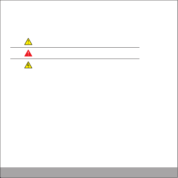
8. Safety
System operation assumes knowledge of the assembly instructions. The
following symbols are used in these assembly instructions:
9.Liability for Material Defects
All components of the device have been checked and tested for functionality at the production
facility. However, if defects occur despite our careful quality control, FÖGE or your dealer must be
notified immediately.
The liability for material defects is 12 months from delivery.
Within this period, defective parts, except for wearing parts, will be repaired or replaced free of
charge, if the device is returned to FÖGE with shipping costs prepaid. Any damage that is caused by
improper handling, the use of force or by repairs or modifications by third parties is not covered by
the liability for material defects. Repairs are carried out exclusively by FÖGE.
Further claims can not be made. Claims arising from the purchase contract remain unaffected. In
particular, FÖGE shall not be liable for any consequential, special, indirect or incidental damage. In
the interest of further development, FÖGE reserves the right to make design changes without
notification.
10. Decommissioning, Disposal
Remove the power supply and output cable on the sensor.
Incorrect disposal may cause harm to the environment.
Dispose of the device, its components and accessories, as well as the packaging materials in
compliance with the applicable country-specific waste treatment and disposal regulations of the
region of use.
Indicates a hazardous situation which, if not avoided, may result
in minor or moderate injury.
Indicates a situation that may result in property damage if not
avoided.
Indicates an electrical shock if not avoided or properly follow
comments.
P6 Ver. 20.3.001
This manual suits for next models
20
Table of contents
Popular Industrial Equipment manuals by other brands


Camlogic
Camlogic PFG-06 Installation and Maintenance

LogicPower
LogicPower LPT- 1000RV user manual

PAW
PAW HeatBloC K31 - DN 20 Installation and operation instruction

Schrack Technik
Schrack Technik LTZ0YT11 Series instruction manual

Xylem
Xylem McDonnell & Miller PSE-800-M Application, Installation, Operation, and Maintenance Manual

schmersal
schmersal AZM150 operating instructions