IBM FC 2704 User manual

TS7700
Installation Instructions
FC 2704, 2725, 2748, & 5512
PN 2726115 EC M14455
EC M14455
IBM

© Copyright IBM Corporation 2016, 2019.
US Government Users Restricted Rights – Use, duplication or disclosure restricted by GSA ADP Schedule Contract
with IBM Corp.

Contents
Installation Instructions ........ v
Before Installation (Sections 1 through
8) ................. 1
1.0 Machines Affected ........... 1
2.0 Related BMs or ECs........... 1
2.1 Prerequisites ............ 1
2.2 Concurrent ECs - Must be installed together . 1
2.3 Companion ECs - May be installed separately 1
3.0 Bill of Materials to be Installed ....... 1
4.0 Preparation ............. 1
5.0 Programming ............. 2
6.0 Purpose and Description ......... 2
7.0 Installation Time ............ 2
8.0 Special Tools/Materials Required ...... 2
Installation (Sections 9 through 12) ... 3
9.0 Safety ............... 3
Safety notices ............. 3
10.0 Details of Installation .......... 7
10.1 Installing the Optical Drive - FC 2748 ... 7
10.2 Installing the TSSC Server - FC 2725 .... 9
10.2.1 Installing the slide rails ...... 10
10.2.2 Installing the shelf assembly .... 13
10.2.3 Installing the cable management arm.. 15
10.3 Installing the KVM (Keyboard/Video/
Mouse) - FC 5512 ........... 20
10.3.1 Installing the display console in the rack 21
10.4 Installing the 26-port Switch and Baffle - FC
2704 ................ 28
10.5 Installing the cables ......... 30
10.5.1 Installing the cables for the model 7060
server .............. 30
10.5.2 Installing the cables for the model 7050
server .............. 33
10.5.3 Installing the cables for the model 7040
server .............. 35
10.5.4 Installing the cables for the model 9020
server .............. 37
10.5.5 Installing the cables for the model M93p
server .............. 39
10.6 Powering on the TSSC ........ 41
10.7 Configuring the TSSC ........ 43
11.0 Test Procedures ........... 43
12.0 Field Updating............ 43
After Installation (Sections 13 and 14) 45
13.0 Publications Update .......... 45
14.0 Parts Disposition ........... 45
Appendix. Installing the ABT power
cables ............... 47
© Copyright IBM Corp. 2016, 2019 iii

iv FC 2704, 2725, 2748, & 5512

Installation Instructions
TS3000 System Console (TSSC)
PN 2726115 EC M14455
Written by:
Checked by:
Status:
D. DaCosta
B. Dennis, S. Roffinoli, J. Garcia
Field Use
Note: This Field Feature Bill of Materials must be used on the customer rack for which it was shipped.
PN 2726115 EC M13631
20 MAY 2016
EC M13922
24 FEB 2017
EC M14111
15 SEP 2017
EC M14494
12 APRIL 2019
EC M14455 18
OCT 2019
© Copyright IBM Corp. 2016, 2019 v

vi FC 2704, 2725, 2748, & 5512

Before Installation (Sections 1 through 8)
Note: If you are going to use Remote Customer System Inventory (RCSI), use the provided barcode label
process for proper component tracking, before starting this install.
The RCSI application automates the inventory checking tasks prior to installing a system or MES. The
IBM Service Representative will install the application on their laptop, download the packing list of parts
to the laptop using the RCSI application, then use a bar code scanner to scan the parts shipped. The
application will process the scanned parts and let the service representative know if there are any missing
parts or extra parts. This process allows the service representative to ensure that they received all parts
required to install an IBM system or MES.
vYou can find the RCSI application guides and resources at:
http://w3.rchland.ibm.com/~cuii/CustomizableContent/rcsi.htm
1.0 Machines Affected
Install feature codes as shown in “6.0 Purpose and Description” on page 2.
2.0 Related BMs or ECs
2.1 Prerequisites
v3952-F05 frame or 3952-F06 frame
vFC 1904 (Redundant AC Power)
2.2 Concurrent ECs - Must be installed together
None.
2.3 Companion ECs - May be installed separately
None.
3.0 Bill of Materials to be Installed
Bill of materials
PN Quantity Description
35P1032 1 Installation Instructions
35P1039 1 FC 2704 - 26-port Ethernet Switch
35P1040 1 FC 2704 - 26-port Ethernet Switch (homologated)
38L6247 1 FC 2725 - Rackmount TS3000 System Console
38L7257 1 FC 2725 - Rackmount TS3000 System Console w8B3646 & #0983 (TAA)
38L6964 1 FC 2748 - Optical Drive
00RY797 1 FC 5512 - KVM Display/Keyboard/Mouse
4.0 Preparation
vFamiliarize yourself with the purpose and details of the installation instruction.
vCheck all items that are listed on the Bill of Materials to ensure that all parts have been received.
© Copyright IBM Corp. 2016, 2019 1

vIt is recommended that you check the PFE website (https://tucln01.ibm.com/tape/tapetec.nsf) for the
latest IIs, fix levels (if required), and vtd_exec packages. Make sure that you use the latest versions
available.
5.0 Programming
None.
6.0 Purpose and Description
Install one or more of the following feature codes:
vFC 2704 - 26-Port Ethernet Switch
vFC 2725 - Rackmount TS3000 System Console (TSSC)
vFC 2748 - Optical Drive
vFC 5512 - KVM Display/Keyboard/Mouse
7.0 Installation Time
Service Action
Estimated install
hours
Estimated machine
hours Estimated system hours
Number of
SSRs
Nonconcurrent 4.0 * 1.0 * 0.5 * 1
* The above install times can vary based on the feature codes that will be installed.
8.0 Special Tools/Materials Required
IBM TS3000 and TS4500 System Console Maintenance Information
A Torq screw driver.
2FC 2704, 2725, 2748, & 5512
Installation (Sections 9 through 12)
9.0 Safety
All normal service support representative safety practices apply.
Safety notices
Observe the safety notices when using this product. These safety notices contain danger and caution
notices. These notices are sometimes accompanied by symbols that represent the severity of the safety
condition.
Most danger or caution notices contain a reference number (Dxxx or Cxxx). Use the reference number to
check the translation in the IBM®Systems Safety Notices, G229-9054 manual.
The sections that follow define each type of safety notice and gives the notices that apply to this
document.
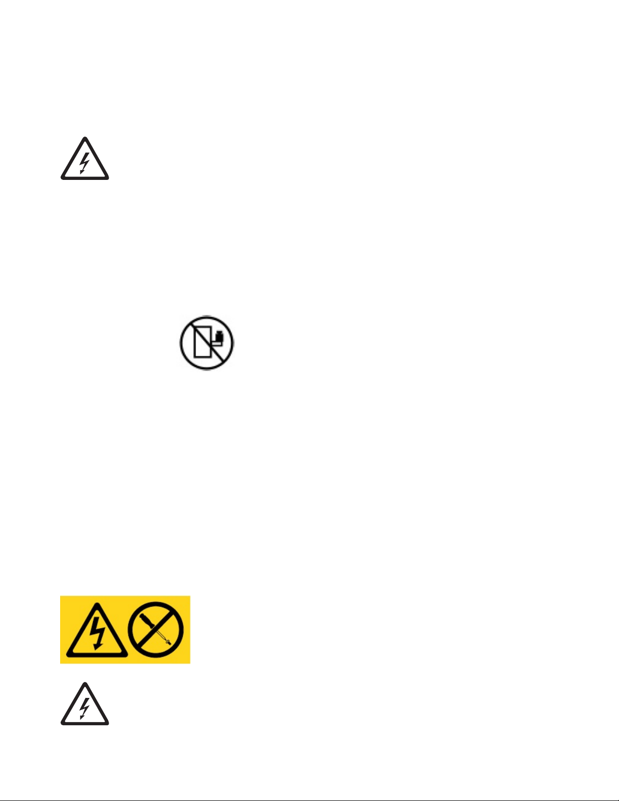
Danger notice
A danger notice calls attention to a situation that is potentially lethal or extremely hazardous to people. A
lightning bolt symbol always accompanies a danger notice to represent a dangerous electrical condition.
A sample danger notice follows:
DANGER: An electrical outlet that is not correctly wired could place hazardous voltage
on metal parts of the system or the devices that attach to the system. It is the
responsibility of the customer to ensure that the outlet is correctly wired and grounded to
prevent an electrical shock. (D004)
© Copyright IBM Corp. 2016, 2019 3

DANGER: When working on or around the system, observe the following precautions:
Electrical voltage and current from power, telephone, and communication cables are
hazardous. To avoid a shock hazard:
vIf IBM supplied the power cord(s), connect power to this unit only with the IBM provided
power cord. Do not use the IBM provided power cord for any other product.
vDo not open or service any power supply assembly.
vDo not connect or disconnect any cables or perform installation, maintenance, or
reconfiguration of this product during an electrical storm.
vThe product might be equipped with multiple power cords. To remove all hazardous
voltages, disconnect all power cords.
– For AC power, disconnect all power cords from their AC power source.
– For racks with a DC power distribution panel (PDP), disconnect the customer’s DC
power source to the PDP.
vWhen connecting power to the product ensure all power cables are properly connected.
– For racks with AC power, connect all power cords to a properly wired and grounded
electrical outlet. Ensure that the outlet supplies proper voltage and phase rotation
according to the system rating plate.
– For racks with a DC power distribution panel (PDP), connect the customer’s DC power
source to the PDP. Ensure that the proper polarity is used when attaching the DC
power and DC power return wiring.
vConnect any equipment that will be attached to this product to properly wired outlets.
vWhen possible, use one hand only to connect or disconnect signal cables.
vNever turn on any equipment when there is evidence of fire, water, or structural damage.
vDo not attempt to switch on power to the machine until all possible unsafe conditions are
corrected.
vAssume that an electrical safety hazard is present. Perform all continuity, grounding, and
power checks specified during the subsystem installation procedures to ensure that the
machine meets safety requirements. Do not continue with the inspection if any unsafe
conditions are present.
vBefore you open the device covers, unless instructed otherwise in the installation and
configuration procedures: Disconnect the attached AC power cords, turn off the applicable
circuit breakers located in the rack power distribution panel (PDP), and disconnect any
telecommunications systems, networks, and modems.
Connect and disconnect cables as described in the following procedures when installing,
moving, or opening covers on this product or attached devices.
To disconnect:
1. Turn off everything (unless instructed otherwise).
2. For AC power, remove the power cords from the outlets.
3. For racks with a DC power distribution panel (PDP), turn off the circuit breakers located
in the PDP and remove the power from the Customer's DC power source.
4. Remove the signal cables from the connectors.
5. Remove all cables from the devices.
To connect:
1. Turn off everything (unless instructed otherwise).
2. Attach all cables to the devices.
3. Attach the signal cables to the connectors.
4. For AC power, attach the power cords to the outlets.
5. For racks with a DC power distribution panel (PDP), restore the power from the
Customer's DC power source and turn on the circuit breakers located in the PDP.
6. Turn on the devices.
Sharp edges, corners and joints may be present in and around the system. Use care when
handling equipment to avoid cuts, scrapes and pinching. (D005)
4FC 2704, 2725, 2748, & 5512
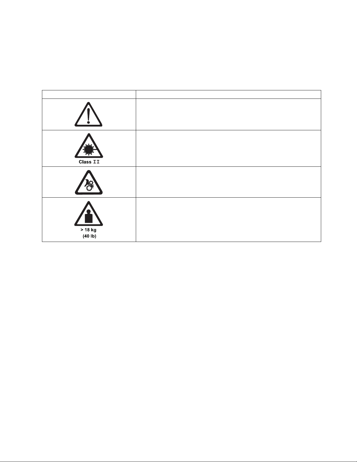
Caution notice
A caution notice calls attention to a situation that is potentially hazardous to people because of some
existing condition, or to a potentially dangerous situation that might develop because of some unsafe
practice. A caution notice can be accompanied by one of several symbols:
If the symbol is... It means...
A generally hazardous condition not represented by other safety symbols.
This product contains a Class II laser. Do not stare into the beam. (C029)
Laser symbols are always accompanied by the classification of the laser as
defined by the U. S. Department of Health and Human Services (for
example, Class I, Class II, and so forth).
A hazardous condition due to mechanical movement in or around the
product.
This part or unit is heavy but has a weight smaller than 18 kg (39.7 lb). Use
care when lifting, removing, or installing this part or unit. (C008)
Sample caution notices follow:
Caution
The battery contains lithium. To avoid possible explosion, do not burn or charge the battery.
Do Not:
vThrow or immerse into water
vHeat to more than 100 degrees C (212 degrees F)
vRepair or disassemble
Exchange only with the approved part. Recycle or discard the battery as instructed by local
regulations. In the United States, IBM has a process for the collection of this battery. For
information, call 1-800-426-4333. Have the IBM part number for the battery unit available when
you call. (C003)
Caution
This part or unit is heavy but has a weight smaller than 18 kg (39.7 lb). Use care when lifting,
removing, or installing this part or unit. (C008)
Caution
The system contains circuit cards, assemblies, or both that contain lead solder. To avoid the
release of lead (Pb) into the environment, do not burn. Discard the circuit card as instructed by
local regulations. (C014)
Caution
Data processing environments can contain equipment transmitting on system links with laser
modules that operate at greater than Class 1 power levels. For this reason, never look into the
Installation (Sections 9 through 12) 5
end of an optical fiber cable or open receptacle. Although shining light into one end and looking
into the other end of a disconnected optical fiber to verify the continuity of optic fibers may not
injure the eye, this procedure is potentially dangerous. Therefore, verifying the continuity of
optical fibers by shining light into one end and looking at the other end is not recommended. To
verify continuity of a fiber optic cable, use an optical light source and power meter. (C027)
(R001 part 1 of 2):
DANGER:
Observe the following precautions when working on or around your IT rack system:
vHeavy equipment–personal injury or equipment damage might result if mishandled.
vAlways lower the leveling pads on the rack cabinet.
vAlways install stabilizer brackets on the rack cabinet unless the earthquake option is to be
installed.
vTo avoid hazardous conditions due to uneven mechanical loading, always install the
heaviest devices in the bottom of the rack cabinet. Always install servers and optional
devices starting from the bottom of the rack cabinet.
vRack-mounted devices are not to be used as shelves or work spaces. Do not place objects
on top of rack-mounted devices. In addition, do not lean on rack mounted devices and do
not use them to stabilize your body position (for example, when working from a ladder).
vEach rack cabinet might have more than one power cord.
– For AC powered racks, be sure to disconnect all power cords in the rack cabinet when
directed to disconnect power during servicing.
– For racks with a DC power distribution panel (PDP), turn off the circuit breaker that
controls the power to the system unit(s), or disconnect the customer’s DC power
source, when directed to disconnect power during servicing.
vConnect all devices installed in a rack cabinet to power devices installed in the same rack
cabinet. Do not plug a power cord from a device installed in one rack cabinet into a
power device installed in a different rack cabinet.
vConnect all devices installed in a rack cabinet to power devices installed in the same rack
cabinet. Do not plug a power cord from a device installed in one rack cabinet into a
power device installed in a different rack cabinet. (R001 part 1 of 2)
Labels
(L001)
DANGER: Hazardous voltage, current, or energy levels are present inside any component
that has this label attached. Do not open any cover or barrier that contains this label.(L001)
6FC 2704, 2725, 2748, & 5512

(L002)
DANGER: Rack-mounted devices are not to be used as shelves or work spaces. Do not place
objects on top of rack-mounted devices. In addition, do not lean on rack-mounted devices
and do not use them to stabilize your body position (for example, when working from a
ladder).(L002)
10.0 Details of Installation
10.1 Installing the Optical Drive - FC 2748
__ 1. See Figure 1 on page 8. Remove the six screws ▌2▐and cover ▌1▐from the TSSC tray.
__ 2. Remove the plastic covering from the hook and loop pieces ▌5▐on the bottom of the tray.
__ 3. Carefully align the front of the optical drive ▌3▐flush to the opening in the tray ▌4▐as you press
the drive on to the hook and loop strips.
__ 4. Connect the USB cable (not shown) from the back of the optical drive to the USB extension cable.
Then, connect the other end of the USB extension cable (not shown) to port 4 ▌6▐on the TSSC.
__ 5. Replace the cover ▌1▐using the six screws ▌2▐.
Installation (Sections 9 through 12) 7
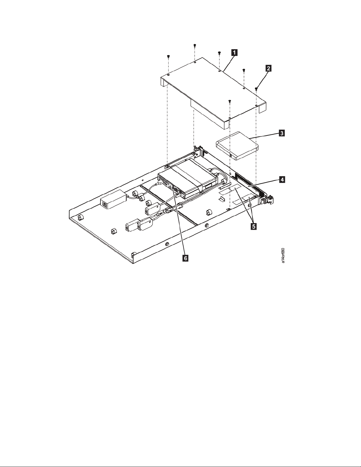
Figure 1. Installing the optical drive
8FC 2704, 2725, 2748, & 5512
10.2 Installing the TSSC Server - FC 2725
The TSSC uses 1U in the frame for installation, and is installed in EIA position 32 in a 3952-F05 frame
and EIA position 20 in a 3952-F06 frame.
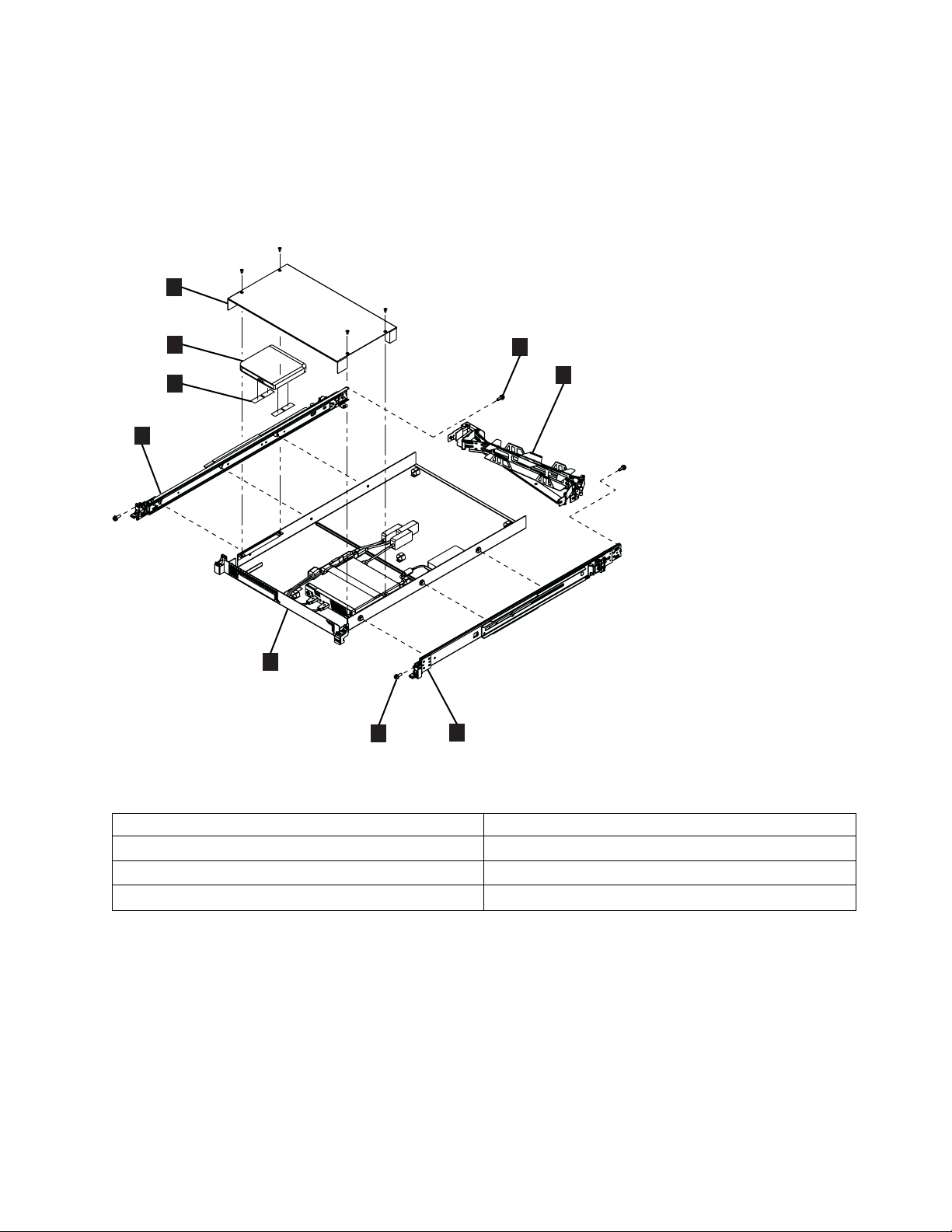
Refer to Figure 2 and Table 1 for components of the TSSC server assembly.
Table 1. TSSC components
▌1▐Cover ▌5▐PC and shelf assembly
▌2▐Optical drive ▌6▐Screw, M6 X 16 (2)
▌3▐hook and loop tape ▌7▐Cable management arm
▌4▐Slide rail ▌8▐Shoulder screw, 10-32 X 3/8" (2)
1
5
4
4
3
2
a14or650
6
7
8
Figure 2. TSSC server assembly
Installation (Sections 9 through 12) 9

10.2.1 Installing the slide rails
Note: The left and right orientation of the slide rails is referenced from the front of the rack. It is easiest
to first install the pins of the slide rail into the back of the rack and then attach the front of the slide rail
to the front of the rack.
__ 1. Use a screwdriver to remove the 10-32 screw (▌8▐in Figure 2 on page 9) from the rear of each slide
rail.
__ 2. Get the left slide rail which is marked with an L (left).
__ 3. See Figure 3. If a thumbscrew is installed in the slide rail ▌1▐, remove it.
__ 4. See Figure 4 on page 11. Working from the front of the rack, install the slide rails in the selected
position. To do so:
__ a. Align the left slide rail with the three holes at the rear of the rack ▌1▐.
__ b. Insert the pins into the holes in the back rail ▌2▐and push firmly until the pins lock into
place in the rack ▌3▐.
Note: It is easier to push the rail into the rear of the rack when you are standing in the
front of the rack.
ts760425
1
Figure 3. Remove the thumbscrew
10 FC 2704, 2725, 2748, & 5512

__ 5. See Figure 5 on page 12. Before installing the front of the slide rail, familiarize yourself with the
movable parts in the front of the slide rail:
__ a. Push up on the front moveable tab ▌1▐.
__ b. Pull out the front latch ▌2▐to slide out the front slide rail.
ts760963
1
2
3
Figure 4. Installing the rails in the rear of the rack
Installation (Sections 9 through 12) 11

__ 6. Figure 6 shows the rails being installed in a rack with square holes. (The holes might instead be
round.) To install the front of the slide rail:
__ a. Pull the rail forward and insert the two pins on the front of the rail into the two lower holes
in the selected position at the front of the rack ▌1▐.
__ b. Push down on the front moveable tab ▌2▐.
__ c. Push in the front latch ▌3▐completely.
__ 7. Repeat steps 4 on page 10 through 6 for the right slide rail, making sure to match the horizontal
position of the left rail.
__ 8. Using the 10-32 screws that you removed in step 1 on page 10, secure each slide rail to the back of
the frame.
1
2
ts760964
Figure 5. Moveable parts of the slide rail
ts760965
1
2
3
Figure 6. Installing the rails in the front of the rack
12 FC 2704, 2725, 2748, & 5512
10.2.2 Installing the shelf assembly
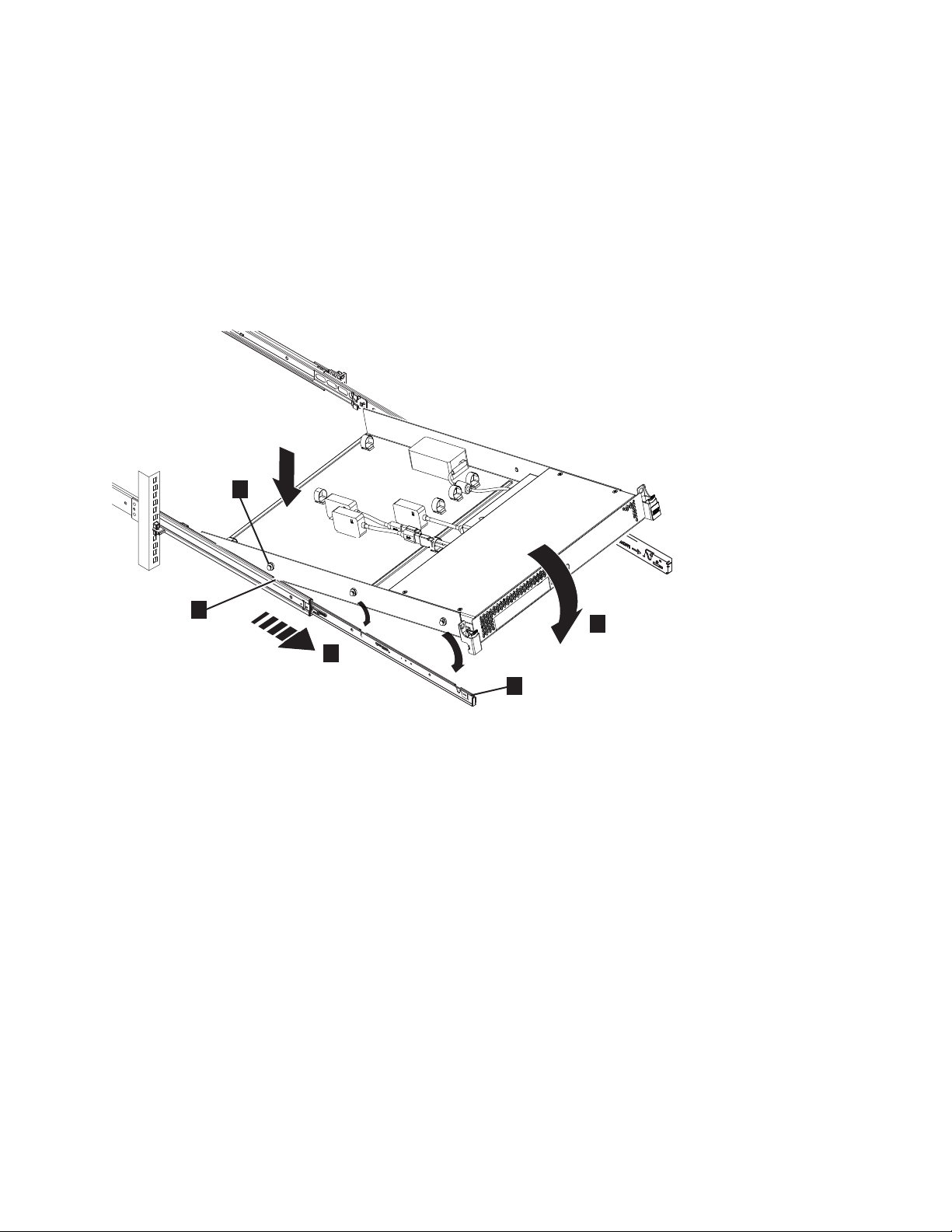
__ 1. See Figure 7. Working from the front of the rack, pull the left and right slide rails forward ▌1▐until
they securely click twice, into place.
__ a. Position the shelf assembly above the slide rails.
__ b. Tilt the back of the tray downward so the rear screw heads ▌2▐on the tray line up with the
rear slots ▌3▐on the side rails.
__ c. Slowly lower the front of the tray ▌4▐until the center and front screw heads slip into the
remaining slots on the rails. You can feel and hear the tray settle into position on the rails.
__ d. Ensure that the front latch ▌5▐slides over the rail heads.
__ 2. See Figure 8 on page 14. Simultaneously lift the locking levers ▌1▐on the slide rails and push the
tray back ▌2▐into the rack. When fully inserted, the tray stops and clicks into place.
a14or648
1
2
3
4
5
Figure 7. Attaching the shelf assembly to the slide rails
Installation (Sections 9 through 12) 13

2
a14or649
1
Figure 8. Insert the shelf assembly into the rack
14 FC 2704, 2725, 2748, & 5512
This manual suits for next models
3
Table of contents
Other IBM Industrial Equipment manuals


