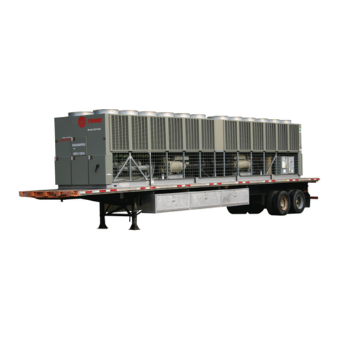
Mechanical Operation -CDHF
Overview
The following description applies to
the Trane Model CDHF Centrifugal
Chiller only. Refer to the appro-
priate operation manual for refri-
geration cycle descriptions
of
other
models.
Each CDHF unit is composed
of
basic components.
-The Evaporator
- 2 Stage Compressor (2 ea.)
-Water-Cooled Condenser
-Single-Stage Economizer (2 ea.)
-Related Interconnecting Piping
Important: The manual is written
describing a SINGLE REFRI-
GERATION CIRCUIT. Please note
that the Duplex has
1WO
(2)
independentcircuits.
refrigerant from the gas), first-stage Lubrication System
variable inletguide vanes, and into
the first-stage impeller. The CDHF compressor lubrication
system, which supplies oil to the
Nota: Inlet guide vanes are compressor motor bearings, is
designed to modulate the flow
of
illustrated in Figure
3.
gaseous refrigerant to meet system
capacity requirements; they also Oil is pumped from the oil tank (i.e.,
prerotate the gas allowing itto enter by a pump and motor located within
the impeller atan optimal angle that the tank) through an oil pressure-
maximizes efficiency at all regulating valve designed to
conditions. maintain a net oil pressure
of
12
to
Compressed gas from the first-
stage impeller is discharged
through the second-stage variable
guide vanes and into the
second-stage impeller. Here, the
refrigerant gas is again
compressed, and then discharged
into the condenser.
18 psid. Itisthen filtered and sent
to the compressor motor bearings.
The oil filterassembly is equipped
with a single rotary valve to isolate
the filter during replacement.
From the bearings, the oil drains
backto the oil tank through return
lines.
Baffles within the condenser shell To ensure proper lubrication and
distribute the compressed prevent refrigerant from condensing
Figure 1 illustrates the general refrigerant gasevenly across the in the oil tank, a 750-watt heater
is
component layout
of
a typical CDHF condenser tube bundle. Cooling immersed in the oil tank. Operating
chiller. tower water, circulated through the in response to a signal from the
condensertubes, absorbs heatfrom UCP, this heaterenergizes as
The duplex unit has (2) CDHF the refrigerant, causing itto needed to maintain an oil tank tem-
compressors on independent condense. The liquid refrigerant perature
of
140 to 145 F {60-63°
C}.
evaporator and condensercircuits. then flows out
of
the bottom
of
the When the chiller is operating, the
Control is accomplished
by
a duplex condenser, passing through an temperature
of
the oil tank is
control module (DCM) as explained orifice plate and into the typically 1150 to 1600 F (46 -720
C).
in
"Electrical Sequence
of
economizer.
Operation" sections
of
this manual. WARNINGI
The economizer reduces the energy A Use
caution
while
working
Cooling-Only Cycle requirements
of
the refrigeration
on
certain
areas
of
the
unit.
When the CDHF is functioning in cycle
by
eliminating the need
to
Surface
temperatures
may
the cooling mode, liquid refrigerant pass all gaseous refrigerant through exceed 150° F
on
the
compressor
is distributed along the length
of
the both stages
of
compression. See discharge,
oil
tank
(heater),
oil
evaporator and sprayed through Figure
2.
Notice that some
of
the
filter,
and
oil
lubrication
lines.
small holes
in
a distributor (Le., liquid refrigerant flashes to a gas
running the entire length
of
the because ofthe pressure drop The oil tank is vented between the
shell) to uniformly coateach created by the orifice plate, thus compressor inletvanes and the
evaporator tube. Here, the liquid further
COOling
the liquid refrigerant. first-stage impeller suction cover.
refrigerant absorbs enough heat This flash gas is then drawn directly During normal system operation,
from the system watercirculating from the economizer into the motorbarrel pressure is greater
through the evaporatortubes to second-stage impeller
of
the than that
of
the oil tank. Therefore,
vaporize. compressor. All remaining liquid any gaseous refrigerant that enters
The gaseous refrigerant is then
drawn through the eliminators
(which remove droplets
of
liquid
refrigerant flows out
of
the the motorbearing cavities
;s
drawn
economizer, passes through toward the oil tank where it is
anotherorifice plate and into the removed by the vent line.
evaporator.
9 CDHF-OM-1
