Valeport MIDAS SVX2 User manual

MIDAS SVX2 Combined SV and CT Profiler -
Operating Manual
Document ID
MANUAL-1553401442-1 issue: 1.5
Date:
March 2022
This confidential document was prepared by the staff of Valeport Limited, the Company, and is the
property of the Company, which also owns the copyright therein. All rights conferred by the law of
the copyright and by virtue of international copyright conventions are reserved to the Company.
This document must not be copied, reprinted or reproduced in any material form, either wholly or in
part, and the contents of this document, and any method or technique available there from, must
not be disclosed to any other person whatsoever without the prior written consent of the Company.
© 2022 Valeport Ltd
Valeport Ltd
St Peter's Quay
Totnes TQ9 5EW
United Kingdom
Phone:
email:
Web:
As part of our policy of continuous development, we reserve the right to alter, without prior notice,
all specifications, designs, prices and conditions of supply for all our equipment

Contents
©2022 –Valeport Ltd
Page | b
Contents
1 Introduction..................................................................................................................................1
2 Specifications ..............................................................................................................................2
2.1 Sensor Specifications ...........................................................................................................2
2.1.1 Sound Velocity.................................................................................................................2
2.1.2 Conductivity .....................................................................................................................2
2.1.3 Pressure...........................................................................................................................2
2.1.4 Temperature ....................................................................................................................2
2.2 Mechanical Specifications ....................................................................................................3
2.2.1 Materials ..........................................................................................................................3
2.2.2 Connectors.......................................................................................................................3
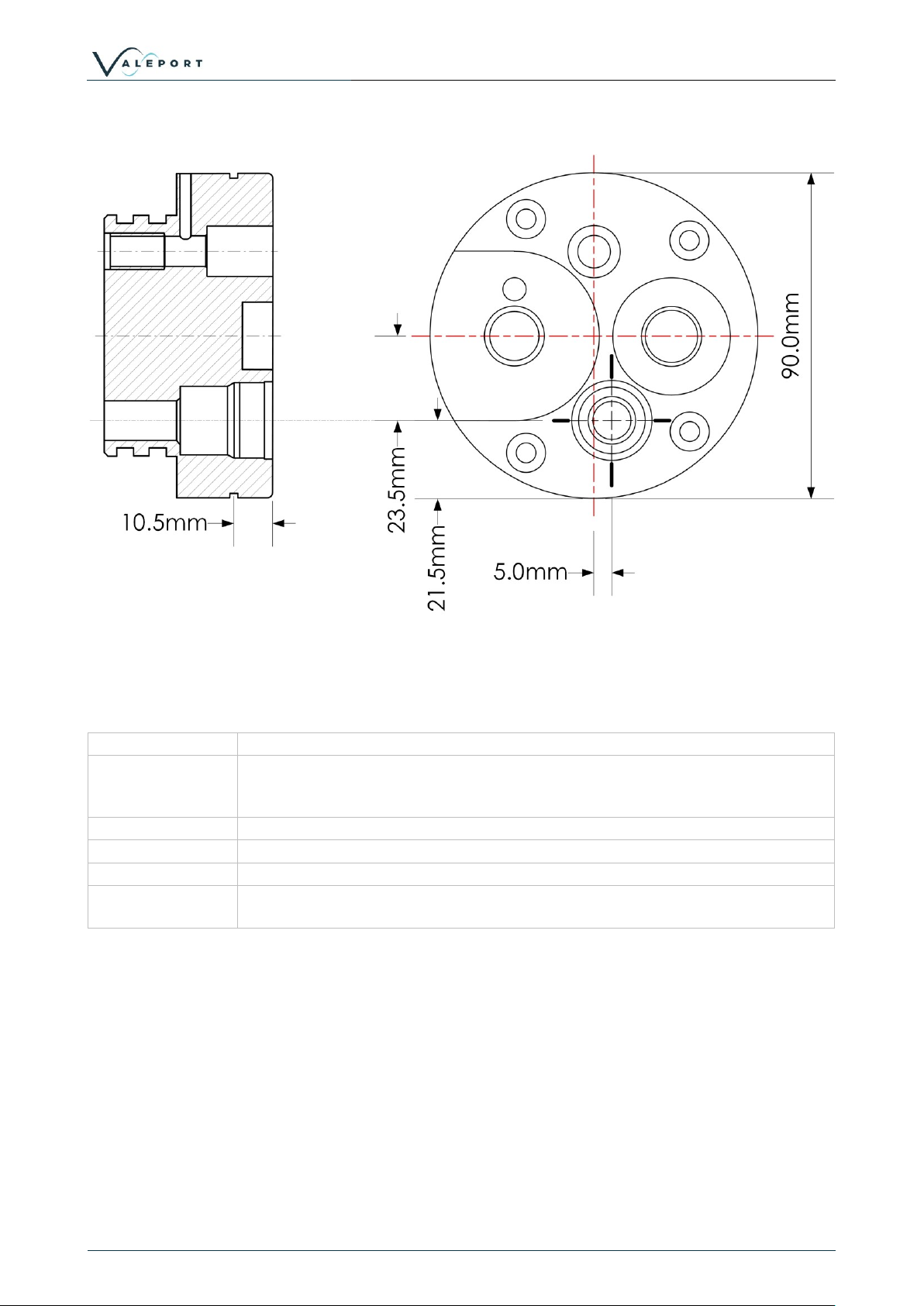
2.2.3 Dimensions ......................................................................................................................4
2.3 Performance Specifications..................................................................................................5
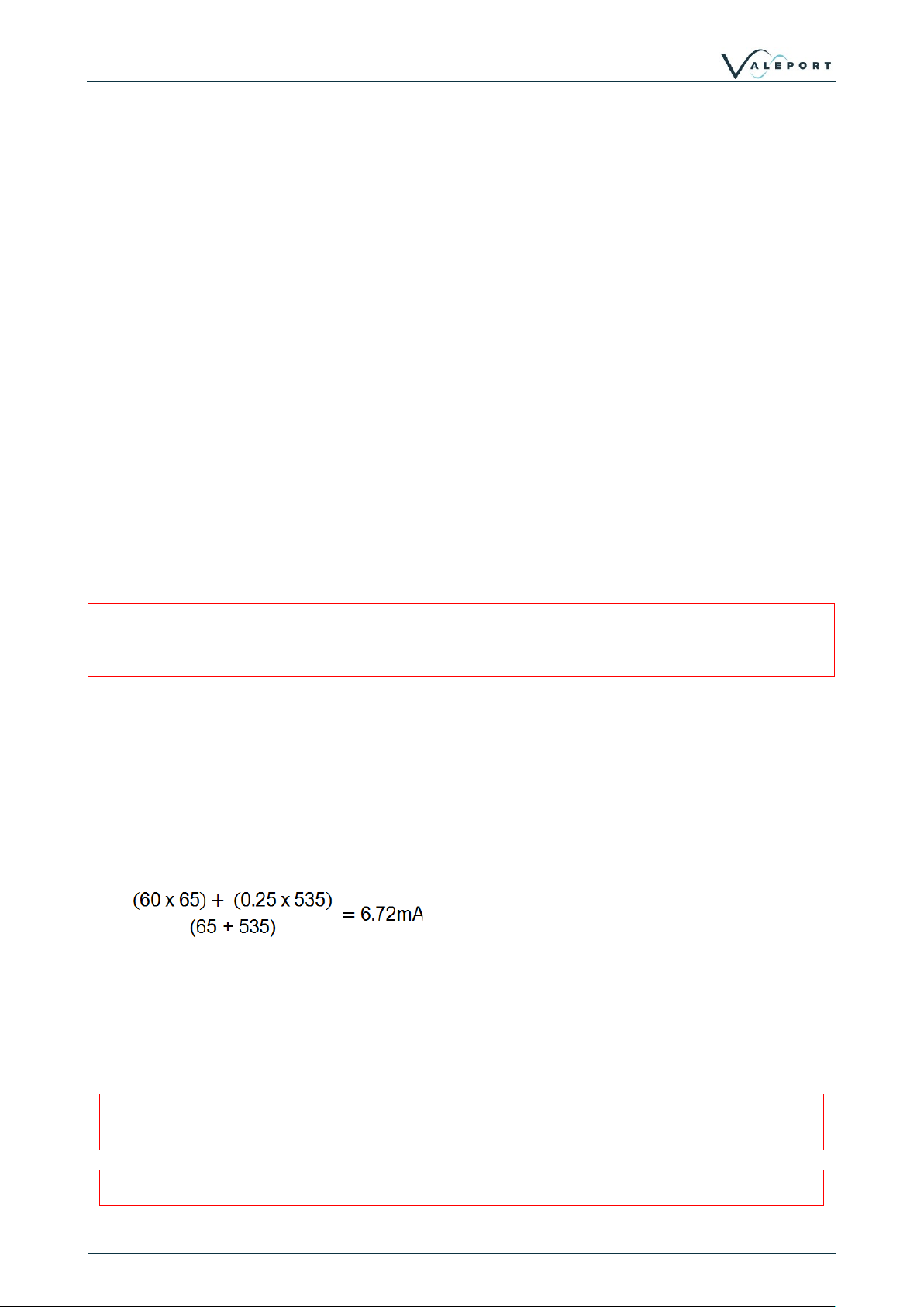
2.4 Sample Battery Life Calculations .........................................................................................6
2.4.1 Based on Memory............................................................................................................6
2.4.2 Based on Batteries ..........................................................................................................8
3 Installation .................................................................................................................................10
3.1 Communications With a PC................................................................................................10
3.2 Deploying the MIDAS SVX2 ...............................................................................................10
3.2.1 Real Time Operation......................................................................................................10
3.2.2 Self Recording Operation ..............................................................................................11
3.2.3 LED Flashing Sequence................................................................................................11
3.2.4 Real Time Data Formats ...............................................................................................11
3.3 Data Download ...................................................................................................................12
4 Maintenance ..............................................................................................................................13
4.1 Changing Batteries .............................................................................................................13
4.1.1 Removing the End Cap Safely ......................................................................................14
4.2 Seals ...................................................................................................................................14
4.2.1 O-Rings..........................................................................................................................15
4.2.2 Anti-Extrusion Rings ......................................................................................................15
5 Wiring Information .....................................................................................................................16
5.1 Switch Plug .........................................................................................................................16
5.2 3m Y Lead (RS232)............................................................................................................16
5.3 3m Switched Y Lead (RS485) ............................................................................................17
6 Frequently Asked Questions .....................................................................................................18
7 EU Declaration of Conformity - CE Marking .............................................................................21

MIDAS SVX2 Combined SV and CT Profiler - Operating Manual
MANUAL-1553401442-1 | issue: 1.5
Page | 1
©2022 –Valeport Ltd
1 Introduction
This manual covers the specification, wiring details and basic maintenance procedures for the
Valeport MIDAS SVX2 Combined SVP / CTD Profiler. Full details of how to operate the instrument
with DataLog x2 software supplied are given in a separate manual.
As standard, the MIDAS SVX2 system consists of the following components:
•Titanium housed instrument
•Stainless steel deployment cage
•3m Y lead (interface to PC)
•Switching Plug
•Basic maintenance tools and spare o-rings
•DataLog x2 Software CD
•Operating Manual
•Transit case
In addition, the following components may be supplied as optional extras:
•RS485 communications adapter
•FSK modem communications adapter (includes pcb in instrument)
•Various lengths & types of signal cable are also available
Instruments are often supplied (on request) with minor adjustments to the above list, such as a
5m Y lead instead of a 3m Y lead for example. Such variations will be detailed on the
instrument packing list, and not in this manual.
If you have any questions about the operation of the instrument, which are not answered by this
manual, please contact your supplier if appropriate, or contact Valeport Ltd directly at the address
given at the front of this manual.

Section 2 | Specifications
©2022 –Valeport Ltd
Page | 2
2 Specifications
2.1 Sensor Specifications
The unit is fitted with the following sensors:
2.1.1 Sound Velocity
Type:
Valeport “time of flight” sound velocity sensor
Range:
1375 to 1900m/s standard.
Accuracy:
± 0.02m/s
Resolution:
0.001m/s
2.1.2 Conductivity
Type:
Valeport inductive coils
Range:
0 - 80mS/cm
Accuracy:
± 0.01mS/cm
Resolution:
0.002mS/cm
2.1.3 Pressure
Type:
Temperature Compensated Piezo-Resistive Sensor
Range:
600Bar absolute (approx 6000m water depth) standard. Others available.
Precision:
± 0.01% Full scale (±0.6m with a 600Bar sensor)
Resolution:
0.001% Full scale (0.06m with a 600 Bar sensor)
2.1.4 Temperature
Type:
Fast response PRT
Range:
-5 to +35°C
Accuracy:
± 0.01°C
Resolution:
0.002°C

MIDAS SVX2 Combined SV and CT Profiler - Operating Manual
MANUAL-1553401442-1 | issue: 1.5
Page | 3
©2022 –Valeport Ltd
2.2 Mechanical Specifications
2.2.1 Materials
Housing:
Titanium
Exceptions:
Sound velocity sensor uses carbon composite rods.
Conductivity sensor is polyurethane and ceramic
Cage:
Stainless steel (316 grade) with polypropylene clamping brackets
Dimensions:
Instrument: 88mm Ø, 665mm long (including connector)
Cage: 825mm long x 140mm x 120mm
Weight (in cage):
13.5kg (in air) 9kg (in water)
Depth Rating:
6000m (unless smaller pressure sensor fitted)
2.2.2 Connectors
Instrument:
10 pin female SubConn bulkhead type (MCBH10F) with lock ring.
Comms Cable:
Valeport 3m Y lead. 10 pin male SubConn line type (MCIL10M) to instrument,
2x 4mm bunch pins to external power, 9 pin female D type to PC.
Switch Plug:
10 pin male SubConn line type (MCIL10M), with lock ring. Note that the switch
cap contains wiring links to activate the instrument.
The Switch plug is not a Dummy Plug

Section 2 | Specifications
©2022 –Valeport Ltd
Page | 4
2.2.3 Dimensions

MIDAS SVX2 Combined SV and CT Profiler - Operating Manual
MANUAL-1553401442-1 | issue: 1.5
Page | 5
©2022 –Valeport Ltd
2.2.3.1 Pressure Sensor Offsets
2.3 Performance Specifications
Memory:
16Mb solid state memory (upgradeable in 16Mb steps to 64Mb)
Internal Power:
8 x 1.5v alkaline C cells. The unit will accept 8 x 3.6v Lithium C cells with no
alterations required
Do not mix battery types
External Power:
Between 9 and 30v DC.
Current Drain:
~60mA at 12v when running, and 0.25mA when in sleep mode.
Sampling Rate:
1, 2, 4 or 8Hz (synchronised)
Data Output:
RS232 or RS485 depending on pin selection. Baud rate is user selectable
from 2400 to 460800

Section 2 | Specifications
©2022 –Valeport Ltd
Page | 6
2.4 Sample Battery Life Calculations
2.4.1 Based on Memory
Battery life based on memory is simple to calculate. Conductivity, temperature and pressure
values use 2 bytes of memory per sample, and sound velocity uses 4 bytes. Therefore total
memory used per record is 4 + (3 x 2) = 10 bytes. Note that in Profile mode, each record is also
assigned a date/time stamp, which uses a further 7 bytes.
The 16 Mbyte memory actually contains 16,777,216 bytes. Allowing a small amount of memory
usage for header files, the memory will store almost 1 million records in Profiling mode, and over
1.6 million records in other modes.
The length of time that this memory will last for obviously depends on sampling scenario. Here are
three examples:
Continuous Data Sampling, 8Hz:
Memory used per second is 10 x 8 bytes = 80 bytes
Total memory fitted is 16,777,216 bytes
Seconds before memory full is 16,777,216 / 80 = (approx) 209,700 seconds
This is equivalent to 58 hours
This period could be doubled by sampling at 4Hz
Burst Sampling, 4Hz:
sampling 1 minute in every 10, recording all data points:
Memory used per burst is 10 bytes x 4Hz x 60 seconds = 2 400 bytes
The memory will therefore be full after 16,777,216 / 2400 bursts = 6 990 bursts
At a 10 minute cycle time, this is 69 900 minutes, which is equivalent to 48 days
Profiling, 6000m cast, measuring every 1 metre:
In this example, the instrument will take 1 reading every metre of both descent and ascent. This
means 6000 data points descending, and a further 6000 ascending. Each record consists of 10
bytes of data and 7 bytes of time stamp. Each record therefore uses 17 bytes. A single cast will
take 12,000 such records, and will therefore use 204,000 bytes.
The 16Mbyte memory will therefore hold approximately 82 casts of data.

MIDAS SVX2 Combined SV and CT Profiler - Operating Manual
MANUAL-1553401442-1 | issue: 1.5
Page | 7
©2022 –Valeport Ltd
2.4.1.1 A Note About Removable Memory
We are sometimes asked whether we offer these devices with removable memory. The answer is
no we don’t, but there are sound reasons for this. It is natural to think that since removable
memory cards are now the norm in consumer electronics, they must be “state of the art” and
therefore desirable in all applications, but this is not necessarily the case.
•An essential feature of an underwater instrument is that it is water-tight; this is achieved by
using various seals on the mechanical parts of the device. Every time that one of these seals
is broken and remade, it introduces a small risk that the seal is not correctly made, and the
instrument could leak. The fewer times that the device has to be opened, the better –you
certainly wouldn’t want to do it after every profile to get the memory card out.
•All memory cards are susceptible to ESD shock (static electricity) while being handled. We
take the view that the value of your data means it shouldn’t be exposed to the possibility of this
risk, which could result in loss of all data on the card.
•Memory cards are not particularly efficient at storing data –they will only accept minimum
sized lumps of data at a time. This may be perfect for a camera where you instantly generate
a few Mbytes, not so for an application where you only want to store a few bytes of data at a
time.
•From a practical point of view, the time taken to connect a cable and extract the data to PC is
actually typically much less than the time to open the device, remove the memory, replace the
memory, and close the device up again.
•The implementation of removable memory is not technically difficult, but we believe that the
disadvantages currently outweigh any possible advantages in this product and its applications.
However, should circumstances change it will of course be considered for future product
enhancements.

Section 2 | Specifications
©2022 –Valeport Ltd
Page | 8
2.4.2 Based on Batteries
The MIDAS SVX2 will function with a voltage supply of between 9 and 30vDC. The voltage output
of the 8 x C cell battery pack will vary according to the type of cell fitted. The most likely cells to be
used will be standard alkaline type (1.5v each) or Lithium cells (3.6v each), giving a 12v nominal
output for alkaline cells, or 28.8v nominal for Lithium cells. The following calculations are based on
the same sampling scenarios as the memory calculations, using figures for a 12v alkaline battery
pack. Each example also gives a figure for a Lithium battery pack, calculated from a basic ratio of
alkaline to Lithium performance.
In all examples, it is taken that an 8 C cell alkaline battery pack will have a nominal capacity of
7.8Ah, and will be 75% efficient (total available charge, 5.85Ah), and that an 8 C cell Lithium pack
will have a nominal capacity of 7.2Ah, and will be 95% efficient (total available charge, 6.8Ah).
Continuous Data Sampling, 8Hz:
At 12v, the instrument draws 60mA when sampling.
Total charge available is 5 850mAh.
Number of hours available is therefore 5850mAh / 60mA = 97 hours.
This is equivalent to just over 4 days.
For Lithium cells, a similar calculation gives around 11 days.
The instrument is effectively operating continuously when in Trip sampling mode, so similar
calculations will apply.
Burst Sampling, 4Hz, Sampling for 1 Minute Every 10 Minutes:
At 12v, instrument draws 60mA when sampling, plus 60mA for 5 seconds at the start of each burst.
It draws 0.25mA when in sleep mode between bursts.
In this scenario then, the instrument will draw 60mA for 65 seconds, and then 0.25mA for 535
seconds.
On average, it will draw:
Total charge available is 5 850mAh.
Number of hours available is therefore 5850mAh / 6.72mA = 870 hours.
This is equivalent to approx 36 days.
For Lithium cells, a similar calculation gives approx 100 days.
The above examples are intended as guides only. Valeport cannot accepts responsibility for
variation in actual performance.
Performance of individual battery cells is not always consistent.

MIDAS SVX2 Combined SV and CT Profiler - Operating Manual
MANUAL-1553401442-1 | issue: 1.5
Page | 9
©2022 –Valeport Ltd
2.4.2.1 A Note About Rechargeable Cells
We are often asked if rechargeable cells can be used. Yes, it is possible to use rechargeable cells,
but we do not recommend it:
•Firstly, the cells cannot be recharged in-situ due to the possibility of the cells giving out gas
inside a sealed instrument, effectively turning it into an explosive device. Whilst this risk is
small, it does exist and therefore must be considered. The risk could be overcome by adding
an air vent to the housing, but this could compromise the water-tight nature of the housing.
Better to remove the risk altogether.
•Secondly, the most commonly used rechargeable cells are NiCad type. These only operate at
around 1.2v maximum and have about 25% of the capacity of an alkaline cell; they therefore
give greatly reduced operating times.
•Modern Li-ion or NiMH cells are more efficient than NiCad cells, but do not yet compare with
alkaline cells. They are also considerably more expensive.
Technology is constantly changing and battery technology, in particular, is at the forefront of
development. As new battery chemistries become available Valeport will advise on a case by case
basis.

Section 3 | Installation
©2022 –Valeport Ltd
Page | 10
3 Installation
The standard system is supplied in an ABS transit case, together with any communications
adaptors ordered. Any additional lengths of signal cable are packed separately.
3.1 Communications With a PC
The MIDAS SVX2 can be set up and interrogated using DataLog x2 software which is supplied
with the instrument or can be downloaded from Valeport website. Please refer to the separate
manual for details of how to use the software.
To connect the instrument directly to a PC for RS232 communications, use the 3m Y lead supplied.
This lead is fitted with a 10 pin SubConn type connector, which should be plugged directly into the
connector on the top of the housing (or to a length of signal cable). The lead also features 2 x
4mm bunch pins for application of external power if required and a 9 way D type connector which
should plug directly into a spare communications port on the back of the PC.
If non-RS232 communications are to be used, via the optional RS485, RS422 or FSK methods,
then the appropriate adapter should be used. Each adapter is supplied with an alternative Y lead,
which should be connected as follows:
Comms
Method
Adaptor
Part No.
Connections
RS485
0400029
Connect 15 pin D type and 4mm plugs from Y lead into adapter.
Connect 9 pin D type from adapter to PC, and 4mm plugs from
adapter to external power, as indicated on adapter housing.
FSK
0400005
Connect 4mm plugs from Y lead into adapter, leaving D types
unconnected (FSK uses power and signal on just two wires).
Connect 9 pin D type from adapter to PC, and 4mm plugs from
adapter to external power, as indicated on adapter
3.2 Deploying the MIDAS SVX2
All parts of the standard system (with the exception of the top part of the 3m Y lead) are designed
for immersion. All communications adaptors (RS485, RS422, FSK) are splash proof, but should be
sited in a dry place, as close to the PC as possible.
The MIDAS SVX2 is supplied with a stainless steel protective cage, but care should still be taken
not to damage the instrument. For profiling work, the recommended deployment method is to
suspend the instrument using the stainless steel wire strop fixed to the top of the cage. For fixed
deployments, the user may wish to remove the cage, and use the grooves in the instrument
housing as clamping points.
3.2.1 Real Time Operation
For real time data output, connect the signal cable to the 10 pin SubConn connector on the
instrument. All Valeport signal cables include a suspension point for strain relief, and a similar
arrangement is recommended for other cable types. Connect the top end of the cable to a PC
using the appropriate method as described above.

MIDAS SVX2 Combined SV and CT Profiler - Operating Manual
MANUAL-1553401442-1 | issue: 1.5
Page | 11
©2022 –Valeport Ltd
3.2.2 Self Recording Operation
For self recording only deployments, the instrument is switched on by insertion of the SubConn
style switch plug. This plug must be inserted for the unit to operate.
The switch plug is NOT just a dummy plug; it contains links between pins as described in
Section 5, which are used to turn the instrument on.
3.2.3 LED Flashing Sequence
The MIDAS SVX2 is fitted with an LED visible through a polycarbonate window in the battery pack.
The LED will flash as detailed below to indicate various states.
Continuous ON for 15 seconds
Occurs when the Switch Plug or cable is connected, indicating
that instrument is on and awaiting communication
1Hz Continual Flashing
Insufficient Power. Change internal batteries, or completely
remove external power, and apply higher voltage
Continuous ON for 2 seconds
Indicates the start of Burst Sampling pattern
5 Rapid Flashes
Indicates the end of Burst Sampling pattern. The duration of the
burst may be calculated as the time between the start and stop
LED sequences, less 5 seconds.
3.2.4 Real Time Data Formats
Sound Velocity<TAB> Units<TAB> Depth<TAB> Units<TAB> Temperature<TAB> Units<TAB>
Conductivity<TAB> Units<TAB><CR><LF>
Example:
1483.576
M/SEC
0010.122
M
0021.291
C
0000.142
MS/CM
1483.578
M/SEC
0010.122
M
0021.293
C
0000.140
MS/CM
1483.578
M/SEC
0010.121
M
0021.284
C
0000.142
MS/CM
1483.581
M/SEC
0010.122
M
0021.287
C
0000.140
MS/CM
If internal salinity calculation is activated:
Sound Velocity<TAB> Units<TAB> Depth<TAB> Units<TAB> Temperature<TAB> Units<TAB>
Conductivity<TAB> Units<TAB>Salinity<TAB>Units<TAB><CR><LF>
1483.576
M/SEC
0010.122
M
0021.291
C
0000.142
MS/CM
0000.124
PSU
1483.578
M/SEC
0010.122
M
0021.293
C
0000.140
MS/CM
0000.122
PSU
1483.578
M/SEC
0010.121
M
0021.284
C
0000.142
MS/CM
0000.124
PSU
1483.581
M/SEC
0010.122
M
0021.287
C
0000.140
MS/CM
0000.122
PSU

Section 3 | Installation
©2022 –Valeport Ltd
Page | 12
3.3 Data Download
On recovery, data can be extracted to PC via the 3m Y lead. This procedure is covered in the
separate software manual for DataLog x2.
To prolong the lifetime of the instrument the following procedures should be carried out once the
instrument has been recovered:
Remove any significant growth from the instrument, taking care not to damage transducer face or
reflector plate of the sound velocity sensor, and paying particular attention to the core of the
conductivity sensor. A high pressure water jet or stiff (not metal) brush is suitable –a hard
toothbrush is ideal.
•Remove any significant growth from the pressure sensor port. Take care not to introduce
any sharp objects onto the sensor face –this may result in sensor damage.
•Check instrument for signs of damage.
•Rinse the instrument in fresh water
•Dry the instrument if possible, paying particular attention to the sensors and connector.
•Repack the instrument in the transit case provided.

MIDAS SVX2 Combined SV and CT Profiler - Operating Manual
MANUAL-1553401442-1 | issue: 1.5
Page | 13
©2022 –Valeport Ltd
4 Maintenance
The MIDAS SVX2 is completely solid state, and therefore requires very little maintenance. Other
than keeping the instrument relatively clean (as described in Section 3.3, Recovery), the only
procedure that the customer will be required to carry out on a regular basis is to change the
batteries. This Chapter also covers details of the o-rings that are fitted to the instrument, and
which should be checked periodically for damage and replaced if necessary.
There is a small chance that pressure can build up inside the instrument housing.See
section 4.1.1 Removing the End Cap Safely
4.1 Changing Batteries
The MIDAS SVX2 accepts 8 x C cells, of either 1.5v alkaline or 3.6v Lithium type. These cells are
arranged in series, so the output voltage is 12v (alkaline) or 28.8v (Lithium). Some example
scenarios for lifetime of these batteries are given in Chapter 2.4.2
The batteries are located in a holder in the top of the instrument, and should be accessed by
removing the connector bulkhead.
1. (This step may be omitted)
For easier access, remove the instrument from the protective cage by loosening the M10 nuts on
the polypropylene clamps. Gently lever these clamps apart, using a screwdriver if necessary.
Slide the instrument out of the cage, in either direction.
2. Remove the 3 M5 x 20 socket cap screws in the connector bulkhead, using the Allen key
provided. Note that these screws are titanium, and should be replaced with titanium screws if
lost. Other materials may suffer galvanic corrosion and may be destroyed.

Section 4 | Maintenance
©2022 –Valeport Ltd
Page | 14
3. Without twisting or putting undue stress on the
SubConn connector slide the bulkhead and
attached battery pack out of the main housing. A
slot between the tube and the bulkhead allows
levering with a screwdriver if necessary. Take
care not to scratch the bore of the tube.
4. A lead connects the battery pack to the electronics inside the tube. This may be disconnected
at the battery pack if required, for ease.
5. Replace the batteries.
6. Check the condition of the bore seal o-rings, and apply a light coating of silicon grease. Ensure
that both they and the anti-extrusion rings sit in the groove correctly, and are free from
damage. Replace them if necessary (refer to Section 4.2).
7. Reattach the connector to the electronics if necessary, and gently slide the battery pack back
into the tube, ensuring that the fixing holes are correctly aligned. Again, take care not to
scratch the bore.
8. Replace the 3 x M5 titanium screws, using a small amount of copper grease (supplied). Do not
force the screws, just tighten firmly.
9. Finally, slide the instrument back into the protective cage. Note that the clamping brackets are
offset, and that the sensor end of the instrument should lie at the long end of the cage.
4.1.1 Removing the End Cap Safely
There is a small chance that pressure can build up inside the instrument housing.
To remove the end cap safely:
•Remove 1 of the bolts securing the end cap and replace with the over long safety bolt supplied
•Make sure that the safety bolt is fully tight, without over tightening it
•Unscrew 1 of the remaining end cap bolts by 2 turns repeat this on the remaining bolt
•If the end cap follows this bolt there is internal pressure trapped in the vessel
•If this is the case then proceed to remove both bolts slowly and carefully, be aware when the final bolt is
removed the cap may pop off but will be retained by the safety bolt
•Once the cap is free from the housing you can remove the safety bolt
4.2 Seals
The MIDAS SVX2 is kept watertight by using o-ring seals and anti-extrusion rings. Double o-ring
seals are used at each end of the titanium housing, although the customer should have no reason
to open any seal other than that at the battery end.
A set of spare o-rings and anti-extrusion rings is included with the equipment. If an o-ring needs
replacing, be sure to use the correct size. If obtaining further spare o-rings from an alternative
source, be sure to obtain the correct material (signified by the last 4 digits of the o-ring code
number).
O-ring size:
200-143-4470
Anti-extrusion ring size:
143

MIDAS SVX2 Combined SV and CT Profiler - Operating Manual
MANUAL-1553401442-1 | issue: 1.5
Page | 15
©2022 –Valeport Ltd
4.2.1 O-Rings
To help preserve the watertight nature of the equipment, please observe the following guidelines:
•Ensure that all o-rings are free from cuts, abrasions or perishing.
•Ensure that all-o-rings are free from dirt, grit, sand, hair and other foreign objects.
•Ensure that an anti-extrusion ring is fitted on the low pressure side of each o-ring (see
Section 4.4.2)
•Whenever an o-ring seal is opened (e.g. when changing batteries), ensure that a light
coating of silicon grease is applied to the o-ring before the seal is closed.
•Ensure that all o-ring protected seals are tightened.
4.2.2 Anti-Extrusion Rings
It is common Valeport practice to fit Anti-Extrusion Rings, also known as AE Rings or Backing
Rings, to o-ring seals on deep water instrumentation.
The function of an AE Ring is to prevent the o-ring from being squeezed out of its groove under
high pressure. Whilst this may not immediately cause a leak, it can damage the o-ring to the
extent that it will not properly seal on subsequent deployments.
Where an AE ring is fitted, Valeport favour a single solid ring type made from
nitrile rubber. These are black or dark grey in appearance, and are
distinguishable from the o-ring itself by having a square cross-section, with a
single concave surface, as illustrated:
These rings should be fitted into the o-ring groove on the “dry”, or low pressure side of the o-ring,
with the concave surface adjacent to the o-ring itself:
It is particularly important to note that in order to fit these rings, they must be stretched slightly to
pass over the instrument body. This stretch does not immediately recover, with the result that the
AE ring may not sit snugly in the groove at first. Fitting the tube to the instrument at this point may
result in the AE ring riding out of the groove, and preventing a proper seal. The instrument may
then leak.
Once an Anti-Extrusion ring has been fitted, please leave a minimum of 30 minutes for it to
recover its shape before fitting the tube.

Section 5 | Wiring Information
©2022 –Valeport Ltd
Page | 16
5 Wiring Information
5.1 Switch Plug
10 Way Male SubConn
Function
1
Link to Pin 10
2
NC
3
NC
4
NC
5
NC
6
NC
7
NC
8
NC
9
NC
10
Link to Pin 1
5.2 3m Y Lead (RS232)
10 Way Male
SubConn
1m Power Cable
4mm Banana
Plugs
9 Way D Type
Function
1
BLUE
BLACK
Power Ground
2
BROWN
RED
Power +V
3
4
5
6
7
2
RS232 Tx (To PC)
8
3
RS232 Rx (From PC)
9
5 (link to 1,6,8,9)
RS232 Ground
SHELL
10
Internal Battery Enable
Link to RS232 Ground

MIDAS SVX2 Combined SV and CT Profiler - Operating Manual
MANUAL-1553401442-1 | issue: 1.5
Page | 17
©2022 –Valeport Ltd
5.3 3m Switched Y Lead (RS485)
10 Way Male
SubConn
SWITCH
BOX
1m White
Cable
4mm Banana
Plugs
15 Way D
Type
9 Way D
Type
Function
1
BLUE
BLACK
Power Ground
2
BROWN
RED
Power +V
3
9
RS485 A
4
10
RS485 B
5
11
6
12
7
2
RS232 Tx
(To PC)
8
3
RS232 Rx
(From PC)
9
5
5 (link to
1,6,8,9)
RS232 Ground
SHELL
SHELL
10
Internal Battery
Enable

Section 6 | Frequently Asked Questions
©2022 –Valeport Ltd
Page | 18
6 Frequently Asked Questions
Why is the SV data from the time of flight sensor different from the CTD data?
Quite simply, the Valeport SV sensor is more accurate than the CTD data. This is because the
CTD formulae (Chen & Millero, Del Grosso etc.) all have errors in them –they were after all based
on observed data taken over 30 years ago using the best technology available at the time. The
Valeport SV sensor simply highlights those errors.
The purpose of this product is actually to provide you with good SV data as well as Density and
Salinity data, which were not previously available on an SVP. The ability to compare the true
sound velocity with the value calculated from CTD is an obvious consequence of this, and raises
questions that had not been previously considered.
Why is the SV data so accurate?
Several reasons. Primarily, we use an advanced digital signal processing technique that removes
virtually all noise from the data, tells us the precise moment that the sound pulse is both
transmitted and received, and allows us to measure the time of flight with a resolution of 1/100th of
a nanosecond (10-11 seconds). Secondly, we have developed a carbon composite material that
doesn’t expand or contract with temperature, so our “known distance” is a constant. Technically,
the material will expand and contract minutely, but over the operating temperatures of the probe, it
is an almost immeasurably small amount, and any change is included in our overall error budget.
Finally, our calibration method removes virtually all the error sources associated with other
techniques.
But don’t you just calibrate it against Chen & Millero?
No we don’t – that would defeat the purpose. While the seawater formulae (Chen & Millero, Del
Grosso etc.) have inherent errors that are accepted as being at best ±0.25m/s, we use a different
formula to calibrate the sensor. Del Grosso also published a formula for speed of sound in pure
water (with Mader, 1972), which is much more accurate. In pure water, the only variable that can
affect sound velocity is temperature (assuming that you are at atmospheric pressure in a laboratory
environment), rather than both temperature and Salinity with the seawater equations. The Del
Grosso & Mader formula therefore has an error of just ±0.015m/s. By calibrating against this rather
against the error-filled seawater equations, we can achieve significantly better performance.
Is a pure water calibration valid?
Absolutely –the purpose of a calibration is just to compare (and adjust) the sensor output against a
known standard –it doesn’t really matter what that standard is, as long it is precisely defined. Our
standard happens to be pure water because it is the most accurately defined standard available.
How Robust is the Conductivity Cell? It looks like it's made of plastic.
We wouldn't go so far as to say it's indestructible, but it is pretty strong. It's actually made from
titanium, with just a thin coating of polyurethane to insulate it. The key thing is the central core,
which is a specialised ceramic material that is particularly durable. It allows the sensor to
overcome a common failing of inductive cells, which is that they rely on the dimensions of the
central core remaining absolutely constant. As pressure increases, most inductive cells compress
slightly, so they may be out of specification at high pressure. The strength of Valeport's cell keeps
the dimensions remarkably stable, so performance is maintained over the entire profile.
Table of contents
Other Valeport Industrial Equipment manuals
Popular Industrial Equipment manuals by other brands

Dorner
Dorner 3200 Series Installation, maintenance & parts manual

schmersal
schmersal AZM300Z-I2-ST-SD2P-T Instructions for operation

ABB
ABB VTC254-14 Operation manual

Barnes
Barnes 3SE-DS Series Installation and operation manual

Peri
Peri 019200 Instructions for use

R.V.R. Elettronica
R.V.R. Elettronica RDMODWEB user manual

Sumitomo Drive Technologies
Sumitomo Drive Technologies PARAMAX SFC Series quick start guide

NOZAG
NOZAG NSE S Series Assembly and operating manual

Challenge
Challenge iJOG Instructions and parts manual

Siemens
Siemens fMRI user guide

Premier
Premier 690L Installation, Inspection, Operation & Maintenance Guide

REMS
REMS SSM 160 R instruction manual