Fohrenbach HT102 User manual


Instruction manualHT102www.foehrenbach.be
Date: August2007Documentrev. : 4Page :2/16/
CONTENTS
1.INTRODUCTION...........................................................................................................3
1.1.HandToolFunction....................................................................................................3
1.2.PhysicalDescription...................................................................................................3
1.3.Principlesof Operation...............................................................................................3
1.4.Specifications.............................................................................................................4
2.OPERATION.................................................................................................................5
2.1.Operating Procedures................................................................................................5
2.2.TerminalInspection....................................................................................................6
3.TROUBLESHOOTING..................................................................................................8
4.PARTSREPLACEMENTPROCEDURES....................................................................9
4.1.AnvilReplacement...................................................................................................9
4.2.Wireand Insulation BarrelCrimpersand TonkerReplacement
(see Figure13)..........................................................................................................11
5.ADJUSTMENTPROCEDURES....................................................................................12
5.1.CrimpHeightAdjustment...........................................................................................12
6.PARTS..........................................................................................................................14
6.1.SpareParts...............................................................................................................14
6.2.PartsOrderingInformation.......................................................................................14
6.3.Hand ToolRepairPolicy............................................................................................14
Instruction manualHT102www.foehrenbach.be
Date: August2007Documentrev. : 4Page :3/16/
1. INTRODUCTION
1.1Hand Tool Function
The HT-0102isamanuallyoperated handtooldesigned forcrimpingloosepiece(individual)
Crimp-to-WireMalePinterminalstowiresizesof22-32 AWG.
1.2Physical Description
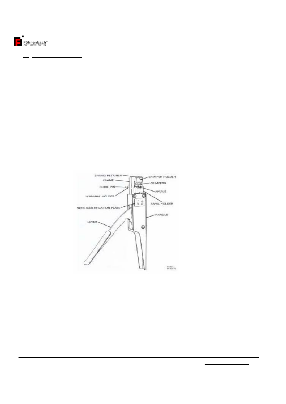
The majorcomponentsthatmakeupthe HT-0102areidentifiedinFigure1. Theseincludea
frame,lever,tooling,toolingholdersand aterminalholder.The heartofthe handtoolisthe
tooling.Thetooling performsthecrimpingoperationand isdivided intotop and bottom
componentgroups.The topgroupconsistsofthosepartswhichremainstationarywiththe
frame.Thebottomgroup containsthosepartsthatmovewiththelever.TheHT-0102 is
equipped withtooling forcrimping twodifferentrangesofwire sizes.Theseareidentified as
"A"and"B"on aplateaffixed tothehand toolframe.The .A.sidetooling isfor crimping
terminalstowiresizesrangingfrom28-32 AWG.The "B"sidetoolingisusedforwiresizes
from22-26 AWG.
1.3Principles ofOperation
The leverattachestothe lowertoolingandprovidesthemechanicaladvantagetogenerate
thenecessarycrimpingpressure.Asthe leverisclosed,aratchetmechanismengagesto
prevent theleverfromopening untilthe crimpingcycleiscomplete.
Whenthe leverispulled closed,the lowertoolingandterminalarepushed upagainstthe
uppertooling.Thecrimpisformed betweenthe wireandinsulation barrelanvilsandthe wire
and insulationcrimpers.
Onceclosed,theratchetreleasesand allowsaspringtopullthe lever open

Instruction manualHT102www.foehrenbach.be
Date: August2007Documentrev. : 4Page :4/16/
1.4Specifications
Whencrimping the MalePintowires,thefollowing parametersmustbemet.
-WireLengthRequirements:
•Minimum.................19-05mm(0.75in.)
•Maximum................AsRequired
-InsulationDiametersofWires:
•"A"Side(28-32 AWG)
LatchHousingand DiscreteApplications.............................0.81-1.37 mm
(0.032-0.054in.)Dia.
•B"Side (22-26 AWG)
LatchHousingand DiscreteApplications..............................0.96-1.52 mm
(0.038-0.060in.)Dia.
-StripLengthofInsulation:
LatchHousingand DiscreteApplications..............................3.81-4.32mm
(0.150-0.170in.)
-WireBarrelCrimpHeight:
•SingleWire (28-32 AWG)OrDoubleWires(30-32AWG).....0.61-0.66 mm
(0.024-0.026in.)
•SingleWire (22-26 AWG)OrDoubleWires(26-28AWG)....0.76-0.81 mm
(0.030-0.032in.)
-InsulationBarrelCrimpHeight:
•"A"Side(28-32 AWG)LatchHousingandDiscreteApplications1.75mm
(0.069in.)Max.Dia.
•B"Side (22-26 AWG)LatchHousingand DiscreteApplications1.75mm
(0.069in.)Max.Dia.
-MalePinTerminals:
•LoosePiece...........................................................................22-32 AWG
NOTE
Loosepieceterminalshavedifferent partnumbersthan reeledterminals
Instruction manualHT102www.foehrenbach.be
Date: August2007Documentrev. : 4Page :5/16/
CAUTION
Ifthe terminaland the toolingare notcompatible,damage tothe toolingcouldresult. Ifyou
wishtouseaterminalwithapartnumberotherthan the one thatwasorderedforthe HT-
0102check withyourdistributortobesurethatthe newterminalnumberiscompatiblewith
yourhandtool.
2. OPERATION
2.1Operating Procedures
WARNING
To preventhand injury,keepfingersfrombetweentheupperand lowertoolingand
from betweentheleverandhandlewhenclosing handtool.
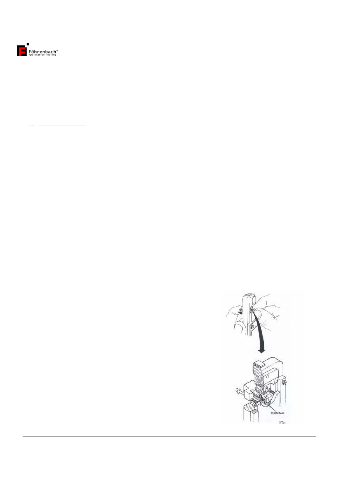
1.Holdthe handtoolsothatthe leverisontheleft. Withyour indexfinger,pushandhold
theterminalholder initsforwardposition (seeFigure 2).
NOTE
Wheninsertingaterminalintotheterminalholderyouwillnoticeaslightdrag(interference)
on the terminal.Thedrag iscaused bythe spring ballplunger (see Figure13itemno.21)
applyingdownwardpressureonthe pinendoftheterminal.
Thisdownward pressure helpstoorientandholdtheterminalinthe terminalholder until
crimped.
2.Insertthe pinend of the terminal, with“U” shaped barrels
up,intotheterminalholderandagainstthe pinshoulder.
Whileholding theterminalagainstthe shoulder,release
theterminalholder.Thisensuresthatthe terminal
remainsinthe properposition whilemovingoverthe
anvil.
Figure2. PositioningTerminalfor
Crimping
Instruction manualHT102www.foehrenbach.be
Date: August2007Documentrev. : 4Page :6/16/
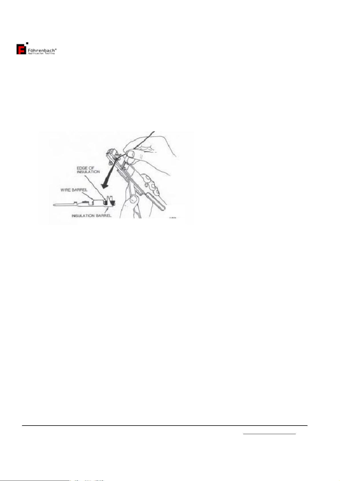
3.Whilegraspingthe leverand the handleportion of theframe,insert awiresothattheend
oftheinsulationiscentered between thewirebarrelandthe insulationbarrelofthe
terminal(seeFigure 3).Analternatemethod istopositionthe endoftheinsulation
againstthetonker(seeFigure13,itemno.2)whichprotrudesfrombetween thecrimpers
(3 &4).Then closethe handtoollever completely.Thiswillcrimptheterminaltothe
wire(s).
4.Releasethe levertoopen the handtoolandremovethecrimped terminalbylightlypulling
straightout on thewire.
CAUTION
Thecrimpheightforthishandtoolwas factoryadjusted.Anychangestothiscrimp
heightadjustmentcouldcause adefectivecrimpor damagetothetooling.
2.2Terminal Inspection
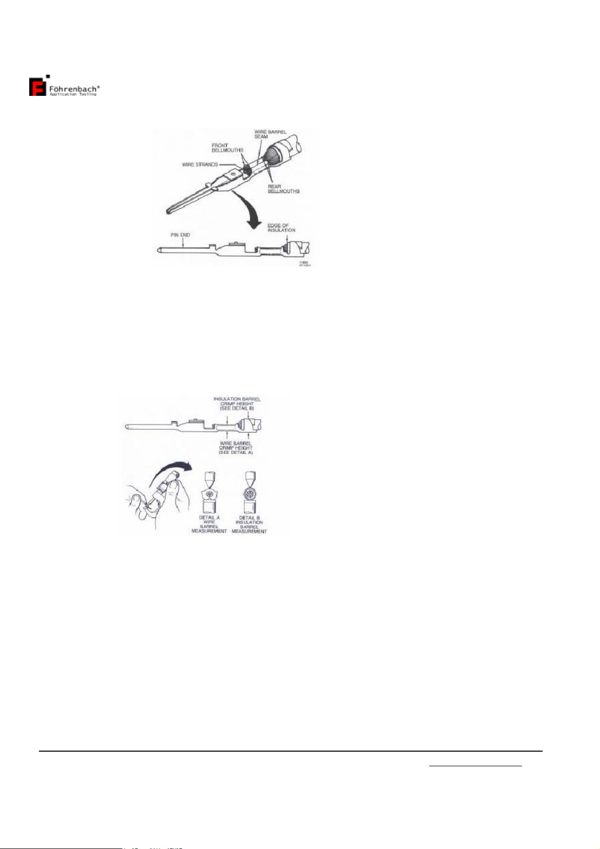
The crimped terminalshouldbe inspected toensurethatthe toolingiscorrectlyaligned and
thatthe wire wascorrectlyinserted. Makethefollowing visualchecks(seeFigure4).
NOTE
Ifinspection ofthe crimped terminalrevealsanydefects,the terminalhasnotbeenproperly
crimpedand shouldbe discarded.
•Checkthatall wirestrandswerecrimpedwithinthewirebarrel.
•Checkthatthe end ofthewireinsulationliesbetween theinsulationand the wirebarrel.
•Checkthatthe bellmouth(s)wereformed correctly.
•Checkthatthe wirebarrelseamiseven andtightlyclosed.
Figure3.Crimping TerminaltoWire
Instruction manualHT102www.foehrenbach.be
Date: August2007Documentrev. : 4Page :7/16/
Next,obtainacrimpheightmicrometer andmeasurethe areasoftheterminalshownin
Figure5.Ifthecrimpheightsdo notmeetthespecificationslistedinSection1,Paragraph
2.4,refertoSection5forproper adjustmentprocedures.
Figure4. Correctly CrimpedTerminal
Figure5.MeasuringCrimpHeightof
Terminal
Instruction manualHT102www.foehrenbach.be
Date: August2007Documentrev. : 4Page :8/16/
3. TROUBLESHOOTING
The troubleshootinginformationprovided inthefollowing chartwillhelpisolateandidentify
crimping problems.
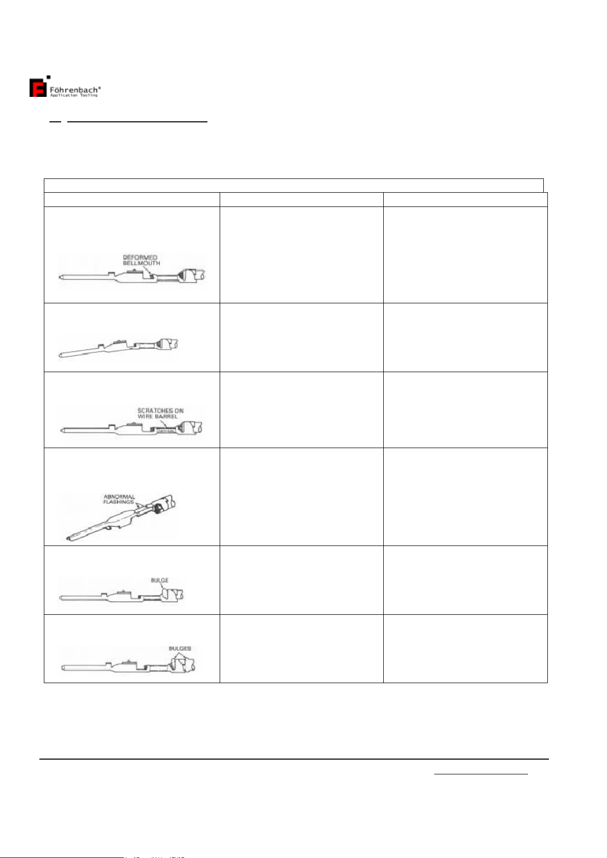
TroubleshootingChart, MalePinTerminal
PROBLEM POSSIBLECAUSE CORRECTIVE ACTION
Bellmouth(s)isdeformedor
improperlypositionedonwire
barrel.
Terminalisnot properly
positionedincrimpingarea.
Insertterminalsoits
shoulder isagainstthe
terminalholder.
Reposition guidepinsuntil
proper bellmouth(s)is
achieved.
Pinendofterminalisbent
down
Terminalissticking inwire
barrelcrimper.
Tooling isbroken or
cracked.
Replacewirebarrelcrimper
asdescribed inSectionIV,
paragraph B.
The sidesofthe terminalswire
barrelarescored orscratched.
Wirebarrelcrimperis
defective. Replacewirebarrelcrimper
asdescribed inSectionIV
paragraph B.
Flashingsformed on the
bottomof thewirebarrelare
unequalor abnormal.
Anvilisworn orbroken Replaceanvilasdescribed
inSection IV,paragraphA.
Insulationbulgesbetween wire
and insulationbarrels.
Wirestriplengthisincorrect,
orwirewasinserted toofar
intothe terminal.
RefertoSection I,
ParagraphD(specifications)
forstriplengthrequirements.
Insulationbulgesaround
insulationbarrel
Wireorinsulationdiameter
isincorrect for the terminal
beingused.
Refertosection I,paragraph
D(specifications)forcorrect
insulationdiameter
requirements.

Instruction manualHT102www.foehrenbach.be
Date: August2007Documentrev. : 4Page :9/16/
4. PARTSREPLACEMENTPROCEDURES
4.1AnvilReplacement
Replaceanvilswhen theyshowexcessivewear orbecomecrackedorchipped.
Removal
1.Removethe capscrewsecuringthe anvilholderassemblytothe handtool(see Figure 6)
and thenremovethe anvilholderassembly.
2.Loosen the twosetscrewsintheanvil holder andremovetheterminalholder (seeFigure
7).
Instruction manualHT102www.foehrenbach.be
Date: August2007Documentrev. : 4Page: 10 / 16/
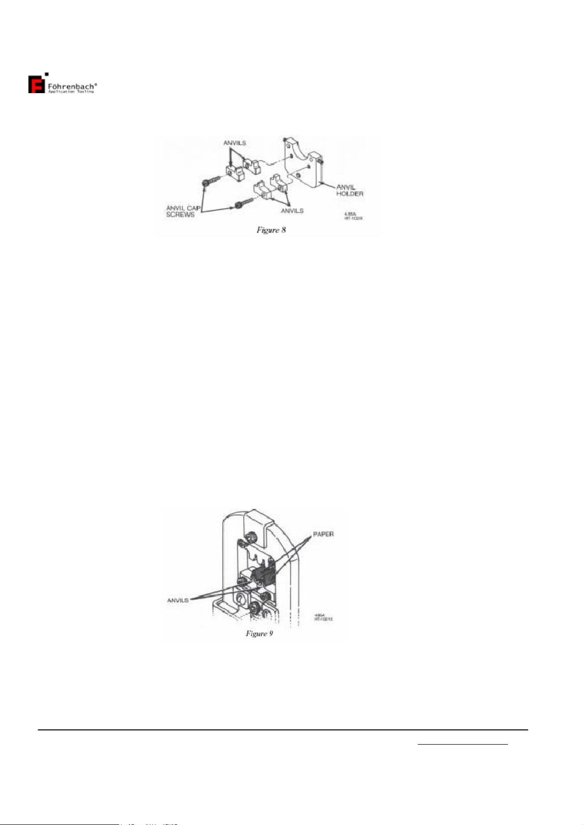
3.Removethe capscrewand defectiveanvil(s)fromtheanvilholder(seeFigure 8).
Installation
NOTE
Whenreplacing theanvils,be sure thatthe partnumberforthenewanvil(s)isthe sameas
theone being replaced.
1.Looselyinstallthe newanvilstothe anvilholderwiththeattaching capscrew(SeeFigure
8).
2.Reinstall theanvilholderontothehand tooland tighten the attaching cap screw.
CAUTION
Topreventtheanvilsfrombeingdamaged during alignment, placeapieceofpaper over
theanvils.
3.Cutouttwostripsofpaper.Then foldthestripsinhalfandplacethemover the anvils(see
Figure9).

Instruction manualHT102www.foehrenbach.be
Date: August2007Documentrev. : 4Page: 11 / 16/
4.Slowlyclosethehandtoollevercompletely.Thiswillalign the anvilstothecrimpers.Then
tightentheanvilcapscrewand releasethe lever.Next,removethepaper fromtheanvils.
5.Reinstall the terminalholdertothe anvilholder.Makesurethattheflatson theend of the
terminalholderguidepinsfacethesetscrewsintheanvilholder.Thentightenthe anvil
holderset screws.
6.Crimpaterminaltothepropersizewire.Then inspecttheterminalasdescribedinsection
II,paragraph B.
4.2WireandInsulation Barrel Crimpersand TonkerReplacement(seeFigure13)
Removal
1.Loosen,butdonotremoveatthistime,the twocap screws(7)that securethe crimpersto
thecrimperholder(1).
2.Removethe capscrew(9)fromthe crimperholder(1).
Then removethe spring retainer(8) and the crimperholder(1)withcrimpersattached.
3.Removethe twotonkersprings(5)andthetwospringguides(6) fromthehand tool
frame.Thiscan be accomplishedbytilting thehandtooldown.
4.Removethe twocap screws(7)thatsecure thecrimperstothe crimperholder(1).
5.Removethe crimpers(3and4)andtonkers(2) fromthe crimper holder(1).
6.Removethe damaged crimper(s)(3)or(4).The topcrimperisthe wire barrelcrimper
(4).
Installation
NOTE
When replacing tooling,alwaysbe sure thatthe partnumberofthe newpartisthe same
numberthatison theoldpartthat wasremoved
7.Placethe insulationcrimper(3)ontotheflatsideofthecrimperholder(1).Placethe wire
barrelcrimper(4) ontheinsulation crimper(3) andlooselyinstallthetwoattaching cap
screws.
8.Inserttonkers(2),withthetoptabsfacing outwards,intothe slotsbetween thewireand
insulationcrimpers.
9.Placeand holdthecrimperassemblyintothehand toolwithcrimper holder (1)onthe
sameside asthe anvil holder (11).
Makesurethatthe tonkers(2)go intothe holesinthetop ofthehandtoolframe.
10.Placespring guides(6) intothe holesintopofthe handtoolframe,theninsertthesprings
(5)intothe holessothatthespringsslipoverthebodyof thespringguides.
11.Placespring retainer(8)overtonkersprings(5).Makesure springsare compressed,then
looselyattachthespring retainer (8)andthe crimperholder(1)tothe handtoolwiththe
attaching capscrew(9).
Instruction manualHT102www.foehrenbach.be
Date: August2007Documentrev. : 4Page: 12 / 16/
12.Toalignthe tooling, closehandtoolcompletelyandholdit init.sclosedposition. Tighten
thetwocapscrews(7)tosecurethecrimperstotheirholder.Thentighten thecap screw
(9),whichsecuresthe crimperholdertothe handtoolframe.
13.Crimpaterminaltoaproper-sizewire andinspecttheterminalasdescribed inSectionII,
paragraph B.
5. ADJUSTMENTPROCEDURES
5.1CrimpHeightAdjustment
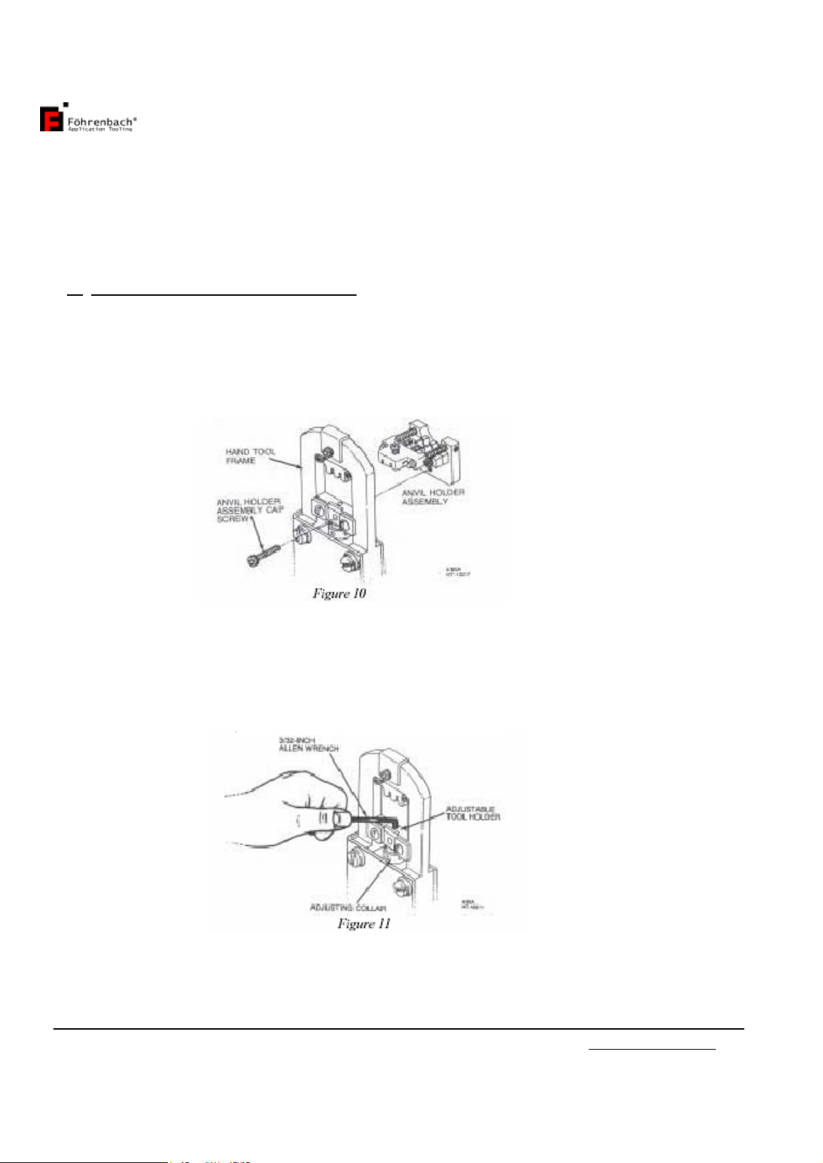
1.Removethe capscrewsecuring theanvilholder assemblytothe handtool(seeFigure
10).Then
removetheanvilholderassembly.
2.Inserta3/32-inchAllen wrenchintotheholeinthe adjustabletoolholderandintothe
sockethead
setscrew(seeFigure11).Turn the setscrew¼turncounterclockwisetounlockthe
adjusting collar.
Instruction manualHT102www.foehrenbach.be
Date: August2007Documentrev. : 4Page: 13 / 16/
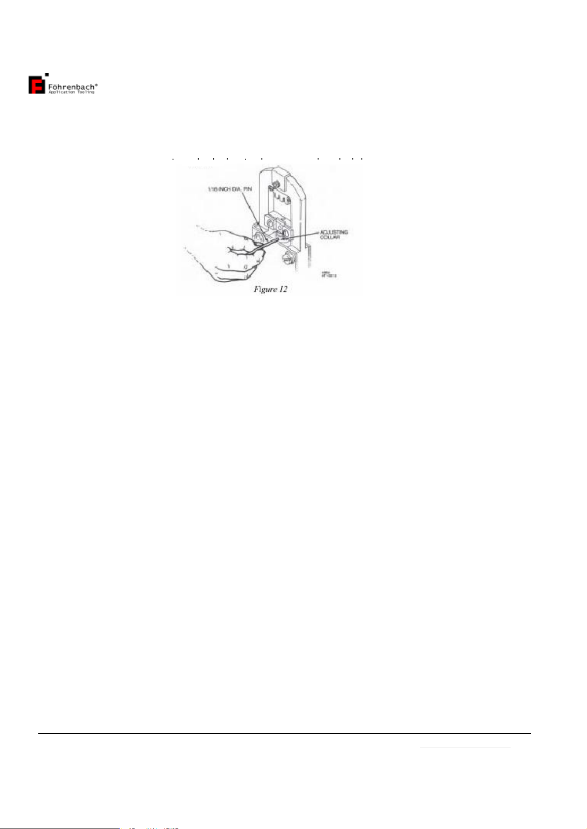
3.Closethehandtoollever oneclicktogainaccesstothe holesinthe sideofthe adjusting
collar.Next,insertapinapproximately1/16-inchindiameter,intooneoftheholesinthe
collar(see Figure12).Then rotatethecollarabout5degreescounterclockwiseto
increasecrimpheightor clockwisetodecreasecrimpheight.
4.Reinstalltheanvil holder assemblyontothe handtooland tighten theattaching cap
screw.
5.Crimpaterminaltothe propersizewireandcheckthe wirebarrelcrimpheightofthe
crimpedterminal.Ifcrimpheightisnotasspecified,removethe anvil holderassembly
and turn theadjustingcollar anadditional5degrees.Thenreinstall theanvilholder
assemblyand againcheck the crimpheight.Continueadjustingthe crimpheightinthis
manneruntilthe propercrimpheightisachieved.
6.Removethe anvil holderassemblyandtightenthesetscrewclockwiseintheadjustable
toolholder. Then reinstallthe anvilholderassemblyand tightenthe attaching cap
screw.

Instruction manualHT102www.foehrenbach.be
Date: August2007Documentrev. : 4Page: 14 / 16/
6. PARTS
6.1SpareParts
ThesearepartsthatFöhrenbachApplicationTooling considerspracticalforthe usertostock
forreplacement. Recommended sparepartsfor thehand toolare specified inboldtypeinthe
partslistforFigure 13.
6.2Parts OrderingInformation
Toobtainreplacementparts,contactFöhrenbachApplication Tooling.
6.3HandToolRepairPolicy
FöhrenbachApplication Tooling chargesastandardratetorepairanyhandtoolnotunder
warranty.FöhrenbachApplication Tooling willrepairthe handtooland returnit toyou bythe
fastestmeanspossible.

Instruction manualHT102www.foehrenbach.be
Date: August2007Documentrev. : 4Page: 15 / 16/
PartsList forFigure 13,HT-0102 HandToolParts
Index
no. PartNo. Description Quantity
1A-857-5 CRIMPERHOLDER 1
2* 104964-1 TONKER 2
3* 108175-1 INSULATIONBARRELCRIMPER22-32 GAUGE
WIRE 1
4* 108176-1 WIREBARRELCRIMPER22-32GAUGEWIRE 1
5A-1153 TONKERSPRING 2
6A-1155 GUIDESPRING 2
7915305-224 SHCS, 4-40 NFX .. LONG 8
8104963-1 SPRINGRETAINER 1
9915305-205 SHCS, 6-40 NFX ½. LONG 2
10 915305-559 SHSS(SETSCREW)2-56NC X 1/8.LONG 2
11 102466-1 ANVILHOLDER 1
12* 108178-1 INSULATIONBARRELANVIL,SIDE“A”, 28-32
GWIRE 1
13* 108178-2 INSULATIONBARRELANVIL,SIDE“B”, 22-26
GWIRE 1
14* 108177-1 WIREBARRELANVIL,SIDE“A”,28-32GWIRE 1
15* 108177-2 WIREBARRELANVIL,SIDE“B”,22-26GWIRE 1
16 102470-1 TERMINALHOLDERSPRING,0.65.LONG 2
17 147070-1 TERMINALHOLDER 1
18 900066-001 O-RING,0.070. I.D.,01-004 2
19 102468-2 GUIDEPIN 2
20 144547-001 GUIDERAIL 2
21 147071-1 TERMINALCLAMP 1
22 147072-1 QUILL PUNCH 1
23 102470-2 PUNCH SPRING,0.300.LONG 1
24 150564-1 COLLAR.NYLON_,PRESS-FIT, 0.0625. I.D. 1
*RecommendedSpareParts

This manual suits for next models
1
Table of contents
Other Fohrenbach Crimping Tools manuals


Popular Crimping Tools manuals by other brands


molex
molex 207129 Series manual

Tyco Electronics
Tyco Electronics 1490749-1 instruction sheet

TE Connectivity
TE Connectivity 2063525-1 instruction sheet

Milwaukee
Milwaukee M18 HCCT109/42 Original instructions

BARTON TOOLS
BARTON TOOLS EC300 instruction manual

Rothenberger
Rothenberger ROFLARE REVOLVER Instructions for use


