Fohrenbach HT95 User manual
HT95
HandpistolminiPV
AWG 22-32
User’sGuide

Instruction manualHT95www.foehrenbach.be
Date: August 2007 Documentrev. : 3Page : 2/ 15
CONTENTS
1.Introduction..........................................................................................................3
1.1Hand toolfunction................................................................................................3
1.2Physicaldescription.............................................................................................3
1.3Principlesof operation..........................................................................................3
1.4Specifications.......................................................................................................4
2.Operation.............................................................................................................5
2.1Operatingprocedures..........................................................................................5
2.2Terminalinspection..............................................................................................6
3.Troubleshooting...................................................................................................8
4.Partsreplacement procedure...............................................................................9
4.1Anvilreplacement.................................................................................................9
4.2Wireand insulation barrelcrimpersand tonkerreplacement...............................10
4.3Holdingpinreplacement......................................................................................11
5.Crimpheight adjustment......................................................................................12
6.Parts.....................................................................................................................14
6.1Spareparts...........................................................................................................14
6.2Partsordering information....................................................................................14
6.3Hand toolrepairpolicy.........................................................................................14
Instruction manualHT95www.foehrenbach.be
Date: August 2007 Documentrev. : 3Page : 3/ 15
1. INTRODUCTION
1.1.HandTool Function
The HT-95isamanuallyoperated handtooldesignedforcrimping loosepiece
(individual)MiniPV™terminalstovarioussizesof wire.
1.2.Physical Description
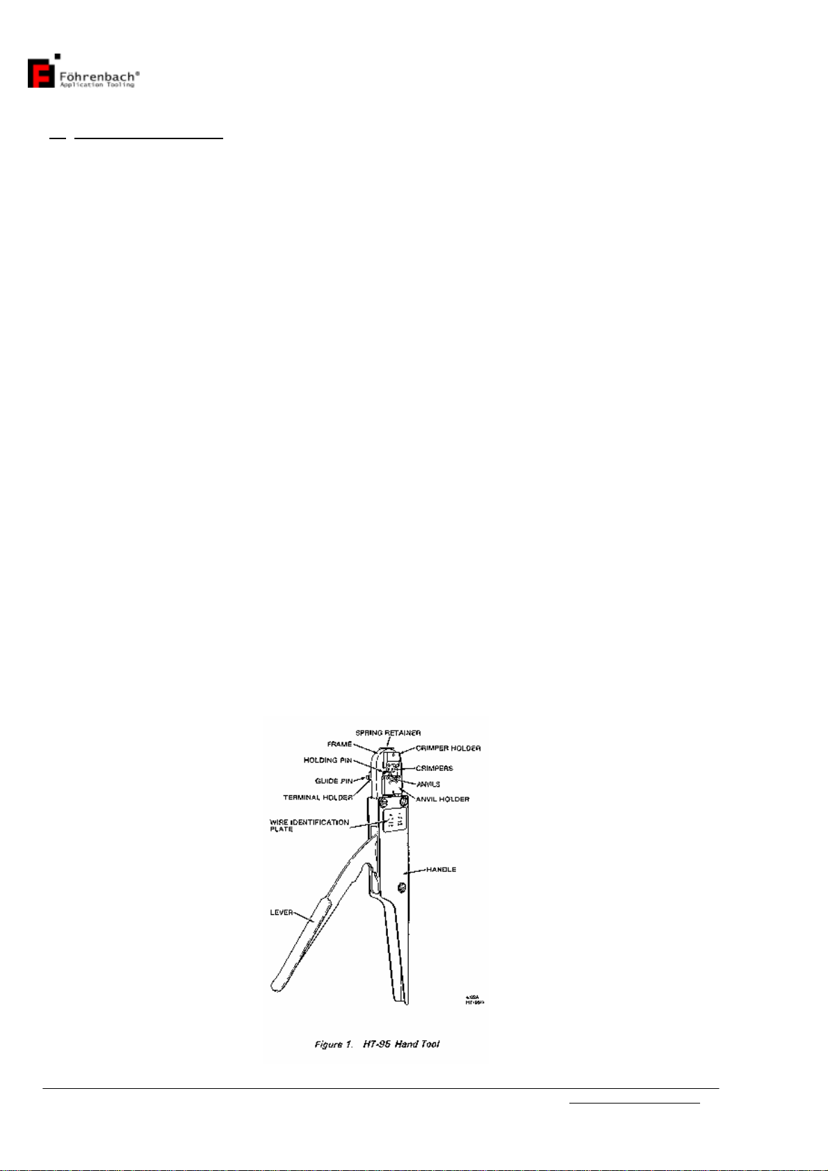
The majorcomponentswhichmakeup the HT-95 areidentified infigure1.These
includeaframe,lever,toolingand tooling holders,and terminalholding pins.Theheart
of the hand toolisthe tooling. The tooling performsthe crimping operation and isdivided
intotopand bottomcomponentgroups.Thetop group consistsofthosepartswhich
remainstationarywiththe frame.The bottomgroup containsthosepartswhichmove
withthe lever.TheHT-95 isequipped withtoolingforcrimpingtwodifferentrangesof
wiresizes.Theseareidentified as"A"and "B"on aplateaffixed tothe hand toolframe.
The "A"side toolingisforcrimping terminalstowiresizesrangingfrom28-32 AWG. The
"B"sidetooling isused forwiresizesfrom22-26 AWG.
1.3.Principles ofOperation
The leverattachestothe lowertooling andprovidesthe mechanicaladvantage to
generatethenecessarycrimping pressure.Asthe leverisclosed,aratchetmechanism
engagestoprevent theleverfromopeninguntilthecrimping cycleiscomplete.
When theleverispulledclosed,the lowertooling andterminalarepushed up against
the uppertooling.The crimpisformed between the wireand insulation barrelanvilsand
the wireandinsulationcrimpers.
Onceclosed, the ratchetreleasesand allowsaspring topulltheleveropen.

Instruction manualHT95www.foehrenbach.be
Date: August 2007 Documentrev. : 3Page : 4/ 15
1.4.Specifications
Whencrimping the MiniPV™towires, thefollowing parametersmust be met.
WireLengthRequirements:
•Minimum...................19.05 mm(0.75 in.)
•Maximum..................AsRequired
Insulation DiametersofWires:
•"A"Side(28-32AWG)..0.71-1.37mm
(0.028-0.054in.)Dia.
•"B"Side(22-26AWG)..0.91-1.52mm
(0.036-0.060in.)Dia.
Striplengthof Insulation:
•Discreteand latch
HousingApplications.3.81-4.31 mm
(0.150-0.170in.)
•Rod Housing............3.30-3.81 mm
Applications...............(0.130-0.150in.)
WireBarrelCrimpHeight: (ForAllApplications)
•SingleWire22-26AWGor
TwoWires26-28 AWG0.81-0.86 mm
(0.032-0.034in.)
•SingleWire28-32AWGor
TwoWires30-32 AWG0.66-0.71 mm
(0.026-0.028in.)
Insulation BarrelCrimpHeight:
•DiscreteApplication.2.84 mm(0.112 in.)Max.
•LatchandRod Housing
Applications...............1.75 mm(0.069 in.)Max.
MiniPV™Receptacles:
•loosePiece22-32AWG
NOTE
Loosepieceterminalshavedifferent part numbersthanreeled terminals.
CAUTION
If theterminaland the toolingarenotcompatible,damage tothe toolingcouldresult.If
you wishtouseaterminalwithapartnumberotherthan the one thatwasordered for
the HT95,check withyourdistributororFöhrenbachApplicationTooling NVtobe sure
that the newterminalnumberiscompatiblewithyourhand tool.
Instruction manualHT95www.foehrenbach.be
Date: August 2007 Documentrev. : 3Page : 5/ 15
2. OPERATION
2.1OperatingProcedures
WARNING
To preventhandinjury,keepfingersfrombetweentheupperandlowertooling
andfrombetweentheleverandhandlewhenclosinghandtool.
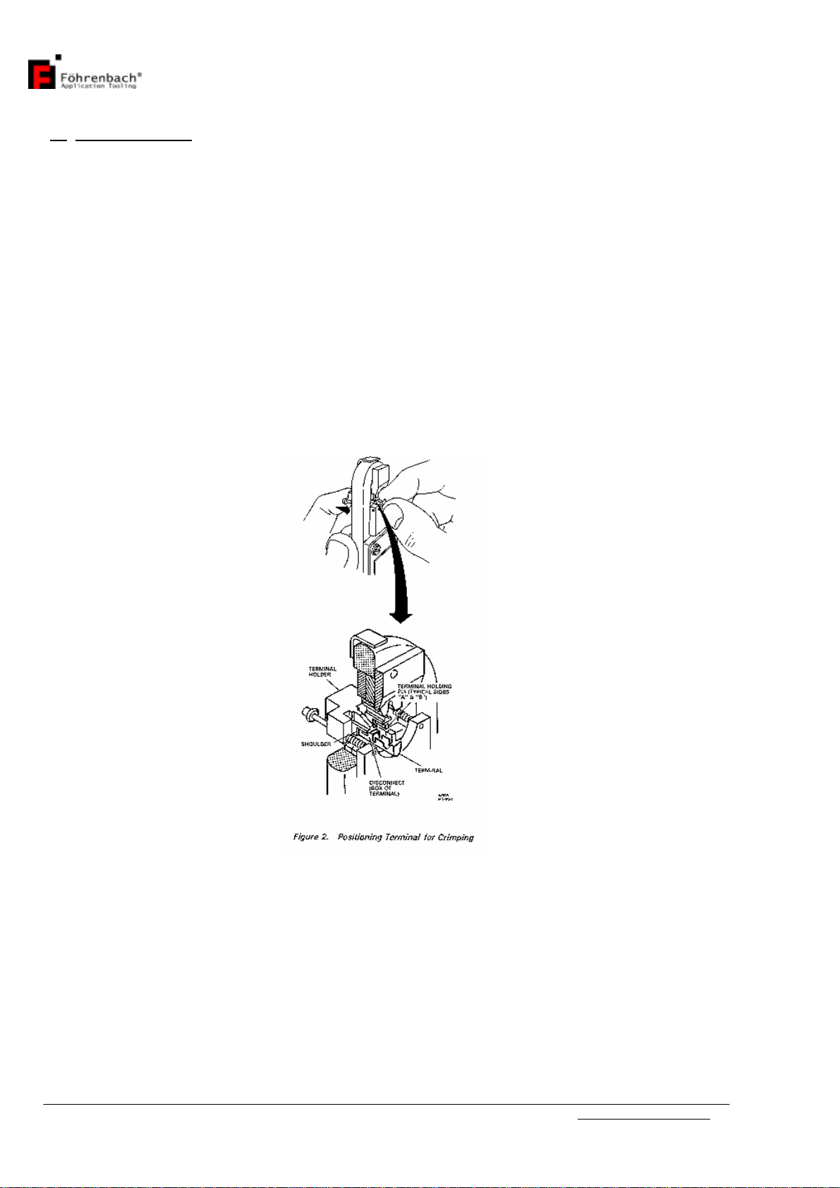
1.Holdthehandtoolsothatthe leverison theleft. Withyourindexfinger,pushand
holdthe terminalholderinitsforwardposition.(See figure2.)
2.Insertthe disconnect(box)portion ofthe terminal,with"U"shaped barrelsup,onto
the holding pinand againstthe pinshoulder.Whileholdingthe terminalagainstthe
shoulder,releasetheterminalholder.Thisensuresthattheterminalremainsin
properposition whilemoving overthe anvil.
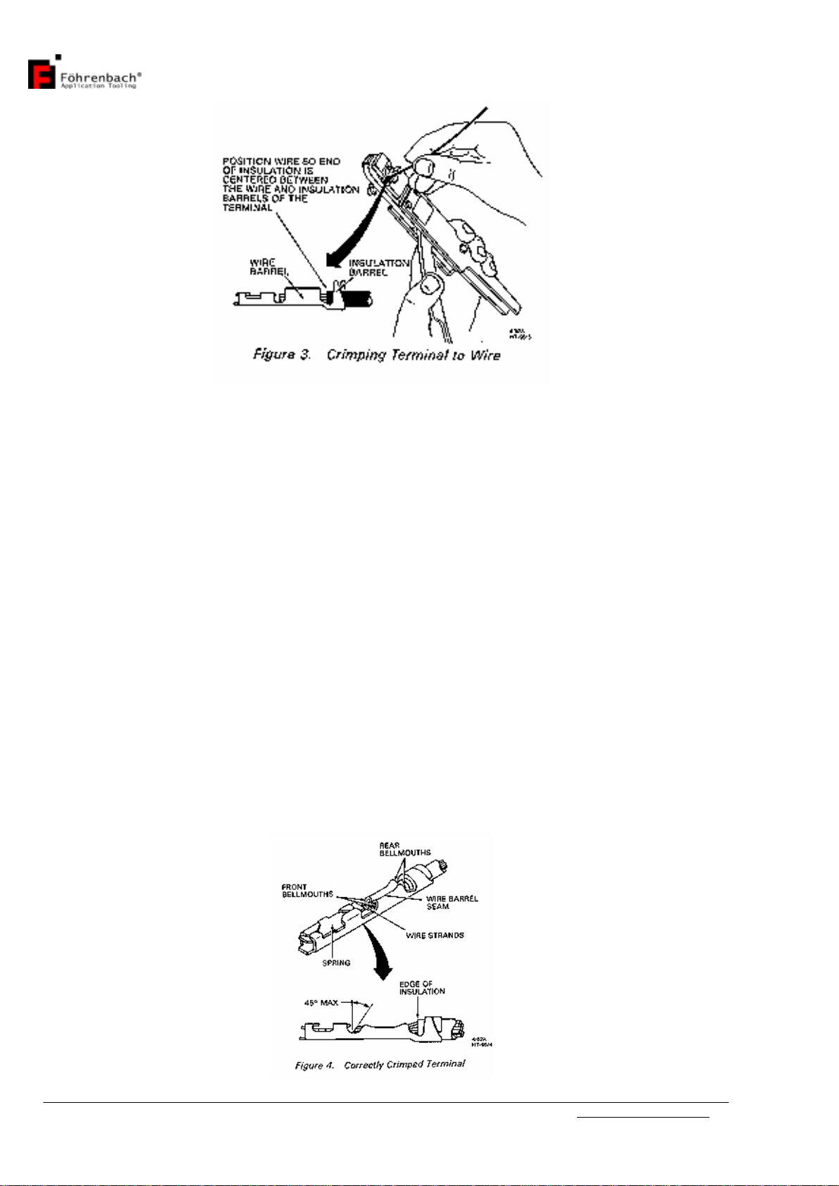
3.Whilegrasping the leverandthe handleportionof the frame, insert awiresothatthe
end of theinsulationiscentered between the wirebarreland the insulation barrelof
the terminal(seefigure3),then closethe handtoollevercompletely. Thiswillcrimp
the terminaltothe wire(s).
Instruction manualHT95www.foehrenbach.be
Date: August 2007 Documentrev. : 3Page : 6/ 15
4.Releasethe levertoopen the hand tooland removethe crimped terminalfromthe
holding pinbylightlypulling straight out onthewire.
CAUTION
The crimpheightforthishand toolwasfactoryadjusted.Anyrandomchangestothis
adjustment couldcauseadefectivecrimpordamage tothe tooling.
2.2Terminal Inspection
The crimped terminalshouldbe inspectedtoensurethatthetoolingiscorrectlyaligned
and thatthe wirewascorrectlyinserted. Makethe following visualchecks (see figure4).
NOTE
If inspection ofthe crimped terminalrevealsanydefects,theterminalhasnotbeen
properlycrimped and shouldbediscarded,
-Check that allwirestrandswerecrimped withinthe wirebarrel.
-Check that theend of the wireinsulation liesbetween the insulation and wirebarrel.

Instruction manualHT95www.foehrenbach.be
Date: August 2007 Documentrev. : 3Page : 7/ 15
-Check that thebellmouth(s)wereformed correctly.
-Check thatthespringwasnotdislodgedfromthe disconnect(box)portion ofthe
terminal.
-Check thatthe endsofthe wirestrandsforman anglenotexceeding approximately
45°.
-Check that thewirebarrelseamiseven andtightlyclosed.
Next, obtainacrimpheightmicrometerand measurethe areasofthe terminalshownin
figure5.If thecrimpheightsdo notmeetthe specificationslisted inSection I, paragraph
D, refertoSection Vforproperadjustment procedures.
Instruction manualHT95www.foehrenbach.be
Date: August 2007 Documentrev. : 3Page : 8/ 15
3. TROUBLESHOOTING
The troubleshooting information provided inthe following chartwillhelpisolateand
identifycrimping problems.
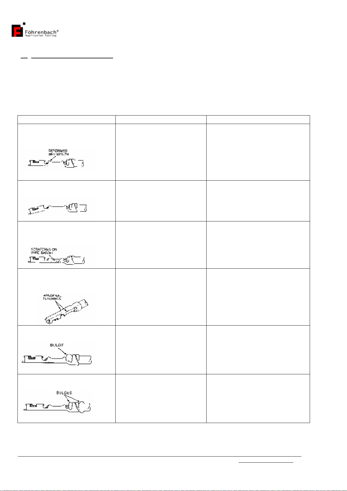
TroubleshootingChart,PV™ReceptaclesHT-95
PROBLEM POSSIBLECAUSE CORRECTIVE ACTION
1. Bellmouth(s)isdeformed
orimproperlypositionedon
wirebarrel.
Terminalisnot properly
positioned incrimping
area.
Loosen thetwo2-56 setscrews
on the sideof theanvilholder
and reposition guide pinsuntil
properbellmouth(s)is
achieved.
2. Disconnect(box)portionof
terminalisbent down.
Terminalissticking inwire
barrelcrimper.
Tooling isbroken or
cracked.
Replacewirebarrelcrimperas
described inSection 2,para-
graph 2.
3. The sidesof the terminals
wirebarrelarescoredor
scratched.
Wirebarrelcrimperis
defective.
Replacewirebarrelcrimperas
described inSection 4,para-
graph 2.
4. Flashingsformed on the
bottomof the wirebarrelare
unequalorabnormal.
Anviliswornorbroken.
Replaceanvilasdescribedin
Section 4, paragraph 1.
5. Insulationbulgesbetween
wireand insulation barrels.
Wireisinsertedtoo farinto
terminal.
Position the endof the
insulation sothatitliesmidway
between the endsof the wire
barreland theinsulationbarrel.
6. Insulationbulgesaround
insulation barrel.
Wiresizeorinsulation
diameterisincorrect for
the terminalbeingused.
RefertoSection1, paragraph
4(specifications)forcorrect
insulation diameter
requirements.

Instruction manualHT95www.foehrenbach.be
Date: August 2007 Documentrev. : 3Page : 9/ 15
4. PARTSREPLACEMENTPROCEDURE
4.1Anvil Replacement(see figure6)
NOTE
Replaceanvilswhen theyshowexcessivewearorarecracked orchipped.
4.1.1.Removal
Whenremoving the anvil,the terminalholder(10)and guidepins(15)mustalsobe
removed.Priortoremoval,notethe position ofthe guidepinsinthe anvilholder,sothat
theycanbepositioned astheywerebeforeremoval:the flatontheguidepinsmustface
the setscrews(12)intheanvilholder(4).
1.Loosen the two2-56setscrews(12)intheanvilholder(4)and removeterminal
holderassembly(10).
2.Remove4-40 capscrew(9)fromthe damagedanvil(s)(5)and (7), or(6)and(8).
3.Removedamaged anvil.
4.1.2.Installation
NOTE
When replacingtooling,be surethatthepartnumberofthe partbeing replaced isthe
sameasthe numberof the partthat wasremoved.
1.Looselyinstallthenewanvil(s)tothe anvilholder(4)withthe4-40cap screw(9).
2.Closehandtoolcompletely;thisalignsanvil tothe crimper.Tighten the 4-40 cap
screw(9), and releasethe lever.
3.Re-installterminalholder(10)tothe anvil holder(4)and tightenthe two2-56
setscrews(12).
4.Crimpaterminaltoaproper-sized wire,andinspecttheterminalasdescribed in
Section II, paragraph B.

Instruction manualHT95www.foehrenbach.be
Date: August 2007 Documentrev. : 3Page : 10 /15
4.2.WireandInsulationBarrel CrimpersandJonkerReplacement
(see figure6)
4.2.1.Removal
1.Loosen butdonotremoveatthistime,the two4-40 cap screws(9)thatsecurethe
crimperstothe crimperholder(1).
2.Removethe 6-40 cap screw(13)fromthe crimperholder(1).Then removethe
spring retainer(21)and the crimperholder(1)withcrimpersattached.
3.Removethe twotonkersprings(19)andthetwospringguides(20)fromthe hand
toolframe. Thiscan beaccomplished bytiltingthe hand tooldown.
4.Removethe two4-40 cap screws(9)thatsecurethe crimperstothe crimperholder
(1).
5.Removethe crimpers(2and 3)and tonkers(18)fromthe crimperholder.6.Remove
the damaged crimper(s)(2or3).The top crimperisthe wirebarrelcrimper(3).
4.2.2.Installation
NOTE
When replacing tooling,always be surethatthe partnumberon the part(s)being
replaced isthe sameasthe numberof the part that wasremoved.
1.Placetheinsulationcrimper(2)ontotheflatside ofthecrimperholder(1).Placethe
wirebarrelcrimper(3)on theinsulation crimper(2)and installtwo4-40capscrews
(9)andlooselytighten.
2.Inserttonkers(18),withthe top tabsfacing outward,intotheslotsbetween the wire
and insulationcrimpers.
3.Placeand holdthe crimperassemblyintothe hand toolon thesameside asthe anvil
holder(4).Makesurethatthe tonkers(18)gointotheholesinthetopofthehand
toolframe.
4.Placespringguides(20)intothe holesinthe top ofthe handtoolframe,then insert
the springs(19)intothe holessothatthe springsslipoverthe shoulderofthe spring
guides.
5.Placespring retainer(21)overtonkersprings(19).Makesurespringsarefully
compressed, then looselyattachthe spring retainer(21)and the crimperholder(1)to
the handtoolwitha6-40cap screw(13).

Instruction manualHT95www.foehrenbach.be
Date: August 2007 Documentrev. : 3Page : 11 /15
6.Toalignthe tooling,closehand toolcompletelyandholditinitsclosedposition.
Tighten the two4-40 cap screws(9)tosecurethe crimperstotheirholder.Then
tighten the 6-40 cap screw(13),whichsecuresthe crimperholdertothe handtool
frame.
7.Crimpaterminaltoaproper-sized wire,andinspecttheterminalasdescribed in
Section II, paragraph B.
4.3.HoldingPinReplacement(see figure6)
NOTE
Whenholding pins(14)becomebent, itisnecessarytoreplacethem.
4.3.1.Removal
NOTE
Whenremoving the holding pin,the terminalholder(10)and guide pins(15)mustalso
be removed.Priortoremoval.notethe positionofthe guide pins(15)intheanvilholder,
sothattheycan be repositioned astheywerebeforeremoval:the flaton the guide pin
must facethe setscrew(12)inthe anvilholder(4).
1.Loosen thetwo2-56 setscrews(12)intheanvilholder(4). Thenremovethe terminal
holderassemblywhichincludesthe terminalholder(10),guide pins(15),"0" rings
(16),holding springs(17),and holding pins(14)attached.
2.Removethe twoholding springs(17)and the guidepins(15)fromthe terminal
holder.
3.Loosen the two2-56 setscrews(12)inthetop ofthe terminalholder(10)which
securetheholdingpins(14).
4.Usingneedle-nosepliers,removebothholdingpins(14)bypullingstraightoutfrom
terminalholder(10). Discardthe damaged holdingpints).
4.3.2.Installation
CAUTION
Overtightening the two2-56 setscrews(12)inthe top ofthe terminalholder(10)can
flatten theholding pins(14), making themextremelydifficult toremove.
1.Install twonewholding pins(14)(0.025 in.squareBergPin™material0.430 in. long)
intoterminalholder(10)untilpinsareflushwiththe extended supports.Besurethat
aflatsideofeachpinisatrightanglestothetwo2-56 setscrewholeson topofthe
terminalholder(10).

Instruction manualHT95www.foehrenbach.be
Date: August 2007 Documentrev. : 3Page : 12 /15
2.Lightlytighten the two2-56 setscrews(12)intothe terminalholder(10)tosecurethe
holding pins(14).
3.Re-installthe twoguidespins(15), "0" rings(16), andthe twoholding springs(17).
4.Re-installthe terminalholder(10)tothe anvilholder(4),and tighten the two2-56
setscrews(12)inthe anvilholder(4)ontotheflatsof the guide pins(15).
5.Crimpaterminaltoaproper-sized wire,andinspecttheterminalasdescribed in
Section II, paragraph B.
5. CRIMPHEIGHTADJUSTMENT(seefigure6)
1.Loosen thetwo2-56 setscrews(12)inthe anvilholder(4).Removeterminalholder
assemblywhichincludesthe terminalholder(10),guide pins(15),"O"rings(16),
holding springs(17), and holdingpins(14)attached.
2.Removethe 6-40 cap screw(13)whichsecuresthe anvil holder(4)tothe adjustable
toolholder(11). Removethe anvilholderwithanvilsattached.
3.Inserta3/32-inchAllenwrenchintothe holeintheadjustabletoolholder(11)and
intothe socket headsetscrew. Turnscrewtothe right 1/4turntounlock theadjusting
collar.
4.Inserttheturned-downend ofthe3/32-inchAllen wrench(suppliedwithhandtool)or
apinapproximately1/16-inchindiameterintoone ofthe fourholesinthe adjusting
collar.Rotatetheadjustingcollarabout5degreestothe righttoincreasethecrimp
height by0.002 inch, ortothe left todecreasecrimpheight by0.002 inch.
5.Re-installanvilholder(4)withanvilsand looselytighten the 6-40 cap screw(13).
6.Closehandtoolcompletelysothattheanvilsalignthemselvestothecrimpers. While
inthe closedposition,tighten thecap screw(13)tolock anvilsintoposition.Open
the handtool.
7.Re-installterminalholderassemblytothe anvilholder(4)and tighten the two2-56
setscrews(12)against theflatsonthe guide pins(15).
8.Crimpaterminaltoawireand recheck the wirebarrelcrimpheight.
a.If crimpheightmeetsspecifications,removeterminalholderassemblyandanvil
holder(4),then lock the adjusting collarbytightening thesetscrewinthe adjustable
toolholder(11).Reinstallterminalholderassemblyand anvilholderasdescribed in
steps5through 7above.

Instruction manualHT95www.foehrenbach.be
Date: August 2007 Documentrev. : 3Page : 13 /15
b.If crimpheight doesnot meet specifications, closethehand toolone click (sothat the
adjusting collarisvisible)and rotatethe adjusting collarasdescribed instep 4.When
correctcrimpheightisattained,lock theadjustingcollarbytighteningthe setscrewin
the adjustabletoolholder(11).Reinstallterminalholderassemblyandanvilholder
asdescribed insteps5through 7above.
PartsListforFigure6. HT-95HandTool Parts
Index
No. Part No Description OtyPer
1 A-857 -5 Crimperholder 1
2* 104958-1Insulation barrelcrimper, 22-26 and 28-32 gauge wire
1
3* 104959-1Wirebarrelcrimper, 22-26 and 28-32 gaugewire 1
4 102466-1Anvilholder 1
5* 104914-A
Insulation barrelanvil, 28-32 gauge wire 1
6* 104914-B
Insulation barrelanvil, 22-26 awgwire 1
7* 104960-A
Wirebarrelanvil, 28-32 gauge wire 1
8* 104960-B
Wirebarrelanvil, 22-26 gauge Wire 1
9 Screw, cap, socket Hd, 4-40 NFx0.37 in. Ig. 4
10 104961-1Terminalholder 1
11 A-856-1 Toolholder, adjustable
12 Setscrew, socket Hd. 2-56NFx0.12 in. Ig. 4
13 Screw, cap, socket Hd. 6-40 NFx0.50 in. Ig 2
14* 104756-1Holdingpin, (0.025"sq. Bergpin™material0.430" Ig.) 2
15 102468-1Guidepin 2
16 "O"ring,01-004 2
17 102470-1Holdingspring 2
18 104964-1Tanker 2
19 A-1153 Springtanker 2
20 A-11 55 Springguide2
21 104963-1Springretainer 1
*Recommended SpareParts

Instruction manualHT95www.foehrenbach.be
Date: August 2007 Documentrev. : 3Page : 14 /15
6. PARTS
6.1SpareParts
ThesearepartswhichF.A.Tooling NVconsiderspracticalforthe usertostock for
replacement. Recommended sparepartsforthe hand toolarespecified inboldtype in
the partslistforfigure6.
6.2PartsOrderingInformation
Toobtainreplacementparts,contactF.A.ToolingNV,Krijgsbaan 128,2640 Mortsel,
Belgium.Provide the description ofthe part, partnumber(ifspecified),quantitydesired,
and alsothehandtoolmodelandserialnumber.
6.3. HandTool RepairPolicy
The repaircostisaccording toexpenses.

Table of contents
Other Fohrenbach Crimping Tools manuals


Popular Crimping Tools manuals by other brands


molex
molex 207129 Series Specification sheet

Emerson
Emerson Klauke EK 120IDCFM Assembly instructions

Tyco Electronics
Tyco Electronics PRO-CRIMPER III 58603-1 instruction sheet

PRECISETOOL
PRECISETOOL XCXY-02 instructions

Hubbell
Hubbell BURNDY PATRIOT 81K2 Series SAFETY OPERATING & MAINTENANCE INSTRUCTIONS

molex
molex 63816-1100 quick start guide