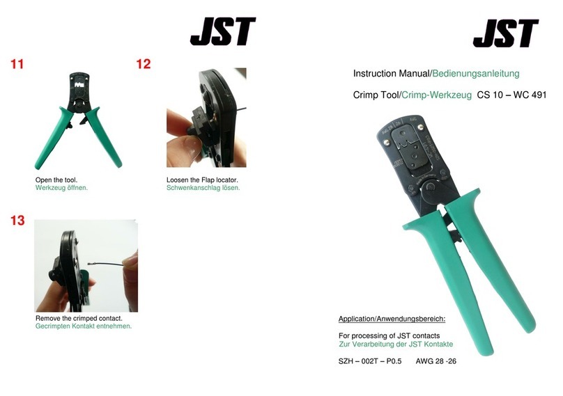
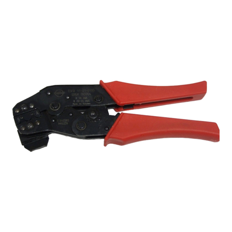
Fohrenbach HT119 User manual

Instruction manualHT119www.foehrenbach.be
Date: August2007Documentrev. : 4Page :2/15/
CONTENTS
1.INTRODUCTION...............................................................................................................3
1.1.HandToolFunction........................................................................................................3
1.2.PhysicalDescription.......................................................................................................3
1.3.Principlesof Operation...................................................................................................3
1.4.Specifications.................................................................................................................4
2.OPERATION.....................................................................................................................5
2.1.Operating Procedures....................................................................................................5
2.2.TerminalInspection........................................................................................................6
3.TROUBLESHOOTING......................................................................................................8
4.PARTSREPLACEMENTPROCEDURES........................................................................9
4.1.AnvilReplacement.......................................................................................................9
4.2.Wireand Insulation BarrelCrimpersand TonkerReplacement
(see Figure13)..............................................................................................................11
5.ADJUSTMENTPROCEDURES........................................................................................12
5.1.CrimpHeightAdjustment...............................................................................................12
6.PARTS..............................................................................................................................13
6.1.SpareParts...................................................................................................................13
6.2.PartsOrderingInformation...........................................................................................13
6.3.Hand ToolRepairPolicy................................................................................................13

Instruction manualHT119www.foehrenbach.be
Date: August2007Documentrev. : 4Page :3/15/
1. INTRODUCTION
1.1Hand Tool Function
The HT-0119 isamanuallyoperatedhandtooldesignedforcrimping loosepiece(individual)
Crimp-to-WireMalePinterminalstowiresizesof22-26 AWG.
1.2Physical Description
The major componentsthatmakeup theHT-0119are identified inFigure1.Theseinclude a
frame,lever,tooling,toolingholdersandaterminalholder.The heartofthehand toolisthe
tooling.The toolingperformsthe crimpingoperationand isdividedintotopandbottom
componentgroups.Thetop group consistsofthosepartswhichremainstationarywiththe
frame.Thebottomgroupcontainsthosepartsthatmovewiththelever.The HT-0119is
equipped with2crimpingplaces.Bothsidesareusedforwiresizesfrom22-26 AWG.
1.3Principles ofOperation
The leverattachestothelowertoolingandprovidesthe mechanicaladvantage togeneratethe
necessarycrimpingpressure.Astheleverisclosed,aratchetmechanismengagestoprevent
thelever fromopeninguntil thecrimpingcycleiscomplete.
When thelever ispulledclosed, thelowertooling andterminalarepushed upagainst theupper
tooling.The crimpisformed betweenthe wireandinsulationbarrelanvilsand thewire and
insulationcrimpers.
Onceclosed,theratchetreleasesand allowsaspringtopullthe lever open

Instruction manualHT119www.foehrenbach.be
Date: August2007Documentrev. : 4Page :4/15/
1.4Specifications
Whencrimping the MalePintowires,thefollowing parametersmustbemet.
-WireLengthRequirements:
•Minimum.................19-05mm(0.75in.)
•Maximum................AsRequired
-InsulationDiametersofWires:
LatchHousingand DiscreteApplications..............................0.96-1.52 mm
(0.038-0.060in.)Dia.
-StripLengthofInsulation:
LatchHousingand DiscreteApplications..............................3.81-4.32mm
(0.150-0.170in.)
-WireBarrelCrimpHeight:
•SingleWire (22-26 AWG).....................................................0.76-0.81 mm
(0.030-0.032in.)
-InsulationBarrelCrimpHeight:
•(22-26AWG)LatchHousing andDiscreteApplications........1.75mm
(0.069in.)Max.Dia.
NOTE
Loosepieceterminalshavedifferent partnumbersthan reeledterminals
CAUTION
If theterminalandthetooling arenot compatible,damage tothetoolingcouldresult.Ifyou wish
touseaterminalwithapartnumberother thanthe onethatwasorderedfortheHT-0119check
withyourdistributortobe surethat the newterminalnumberiscompatiblewithyourhandtool.

Instruction manualHT119www.foehrenbach.be
Date: August2007Documentrev. : 4Page :5/15/
2. OPERATION
2.1Operating Procedures
WARNING
To preventhand injury,keepfingersfrombetweentheupperandlowertooling andfrom
betweentheleverandhandlewhenclosinghandtool.
1.Holdthe hand toolsothattheleverisonthe left.Withyourindexfinger,pushand holdthe
terminalholderinitsforwardposition(seeFigure2).
NOTE
Wheninsertingaterminalintotheterminalholderyouwillnoticeaslightdrag(interference)on
theterminal.The dragiscaused bythespring ballplunger(seeFigure13itemno.21)
applyingdownwardpressureonthe pinendofthe terminal.
Thisdownwardpressurehelpstoorientandholdtheterminalintheterminalholderuntil
crimped.
2.Insertthepinendofthe terminal,with“U” shaped barrels
up,intotheterminalholderandagainstthepinshoulder.
Whileholdingtheterminalagainsttheshoulder,release
theterminalholder. Thisensuresthat theterminalremains
inthe properposition whilemovingovertheanvil.
3.Whilegraspingthelever and thehandleportion ofthe
frame,insertawiresothattheendofthe insulation is
centered betweenthe wirebarrelandtheinsulationbarrel
oftheterminal(see Figure3).Analternatemethodisto
position theend oftheinsulation againstthetonker(see
Figure13,itemno.2)whichprotrudesfrombetween the
crimpers(3&4).Then closethehand toollever
completely.Thiswill crimpthe terminaltothe wire(s).
Figure2. PositioningTerminalfor
Crimping

Instruction manualHT119www.foehrenbach.be
Date: August2007Documentrev. : 4Page :6/15/
4.Releasethe levertoopenthehand tooland removethe crimped terminalbylightlypulling
straightout on thewire.
CAUTION
Thecrimpheightforthishandtoolwasfactoryadjusted.Anychangestothiscrimp
heightadjustmentcouldcause adefectivecrimpor damagetothetooling.
2.2Terminal Inspection
The crimped terminalshouldbeinspected toensure that thetoolingiscorrectlyaligned andthat
thewirewascorrectlyinserted.Makethefollowingvisualchecks (see Figure4).
NOTE
Ifinspectionofthe crimpedterminalrevealsanydefects,the terminalhasnotbeenproperly
crimpedand shouldbe discarded.
Figure3.Crimping TerminaltoWire

Instruction manualHT119www.foehrenbach.be
Date: August2007Documentrev. : 4Page :7/15/
•Checkthatall wirestrandswerecrimpedwithinthewirebarrel.
•Checkthatthe end ofthewireinsulationliesbetweentheinsulationand the wirebarrel.
•Checkthatthe bellmouth(s)wereformed correctly.
•Checkthatthe wirebarrelseamiseven andtightlyclosed.
Next,obtainacrimpheightmicrometerand measuretheareasofthe terminalshowninFigure
5.IfthecrimpheightsdonotmeetthespecificationslistedinSection 1,Paragraph 2.4,refer to
Section 5forproperadjustment procedures.
Figure4.Correctly CrimpedTerminal
Figure5.MeasuringCrimpHeightof
Terminal

Instruction manualHT119www.foehrenbach.be
Date: August2007Documentrev. : 4Page :8/15/
3. TROUBLESHOOTING
The troubleshootinginformationprovided inthefollowing chartwillhelpisolateandidentify
crimping problems.
TroubleshootingChart, MalePinTerminal
PROBLEM POSSIBLECAUSE CORRECTIVE ACTION
Bellmouth(s)isdeformed or
improperlypositioned on wire
barrel.
Terminalisnot properly
positionedincrimpingarea.
Insertterminalsoitsshoulder
isagainst theterminalholder.
Reposition guidepinsuntil
properbellmouth(s)is
achieved.
Pinendofterminalisbent
down
Terminalissticking inwire
barrelcrimper.
Tooling isbrokenorcracked.
Replacewirebarrelcrimper
asdescribedinSectionIV,
paragraphB.
The sidesofthe terminalswire
barrelarescored orscratched.
Wirebarrelcrimperis
defective. Replacewirebarrelcrimper
asdescribedinSectionIV
paragraphB.
Flashingsformed on the
bottomof thewirebarrelare
unequalor abnormal.
Anvilisworn orbroken Replaceanvilasdescribed in
Section IV, paragraphA.
Insulationbulgesbetween wire
and insulationbarrels.
Wirestriplengthisincorrect,
orwire wasinserted too far
intothe terminal.
Refer toSectionI, Paragraph
D(specifications)forstrip
lengthrequirements.
Insulationbulgesaround
insulationbarrel
Wireorinsulationdiameter is
incorrectforthe terminal
beingused.
Refer tosection I,paragraph
D(specifications)forcorrect
insulation diameter
requirements.

Instruction manualHT119www.foehrenbach.be
Date: August2007Documentrev. : 4Page :9/15/
4. PARTSREPLACEMENTPROCEDURES
4.1AnvilReplacement
Replaceanvilswhen theyshowexcessivewear orbecomecrackedorchipped.
Removal
1.Removethe capscrew securingtheanvil holder assemblytothe handtool(seeFigure 6)
and thenremovethe anvilholderassembly.
2.Loosen the twosetscrewsintheanvil holder andremovetheterminalholder(seeFigure 7).
3.Removethe capscrewand defectiveanvil(s)fromtheanvilholder (seeFigure 8).

Instruction manualHT119www.foehrenbach.be
Date: August2007Documentrev. : 4Page: 10 / 15/
Installation
NOTE
When replacing theanvils,besurethatthepartnumberforthenewanvil(s)isthesameasthe
one beingreplaced.
1.Looselyinstallthe newanvilstothe anvil holder withtheattachingcap screw(See Figure
8).
2.Reinstall theanvilholderontothehand tooland tighten the attaching cap screw.
CAUTION
Topreventtheanvilsfrombeing damagedduringalignment,placeapieceofpaperover
theanvils.
3.Cutouttwostripsofpaper.Thenfoldthestripsinhalfand placethemovertheanvils(see
Figure9).
4.Slowlyclosethehand toollevercompletely.Thiswillalignthe anvilstothe crimpers.Then
tightentheanvilcapscrewand releasethe lever.Next, removethepaper fromtheanvils.
5.Reinstall the terminalholdertotheanvil holder.Makesurethattheflatsontheendofthe
terminalholderguidepinsfacethesetscrewsinthe anvilholder.Then tightentheanvil
holderset screws.
6.Crimpaterminaltotheproper sizewire.Theninspectthe terminalasdescribed insectionII,
paragraph B.

Instruction manualHT119www.foehrenbach.be
Date: August2007Documentrev. : 4Page: 11 / 15/
4.2WireandInsulation Barrel Crimpersand TonkerReplacement(seeFigure13)
Removal
1.Loosen,butdonotremoveatthistime,the twocap screws(7)thatsecurethecrimpersto
thecrimperholder(1).
2.Removethe capscrew(9)fromthe crimperholder(1).
Then removethe spring retainer(8) and the crimperholder(1)withcrimpersattached.
3.Removethe twotonkersprings(5)andthetwospring guides(6) fromthehandtoolframe.
Thiscan beaccomplished bytiltingthehand tooldown.
4.Removethe twocap screws(7)thatsecure thecrimperstothe crimperholder(1).
5.Removethe crimpers(3and4)andtonkers(2) fromthe crimper holder(1).
6.Removethe damaged crimper(s)(3) or(4). The topcrimper isthewirebarrelcrimper (4).
Installation
NOTE
When replacing tooling,always be sure thatthe partnumberofthenewpartisthesame
numberthatison theoldpartthat wasremoved
7.Placetheinsulationcrimper(3) ontotheflatsideofthe crimperholder (1).Placethewire
barrelcrimper(4)onthe insulationcrimper(3)andlooselyinstallthetwoattachingcap
screws.
8.Inserttonkers(2),withthe toptabsfacingoutwards,intothe slotsbetween thewireand
insulationcrimpers.
9.Placeandholdthecrimper assemblyintothe hand toolwithcrimperholder(1)onthesame
side asthe anvilholder(11).
Makesurethatthe tonkers(2)go intothe holesinthetop ofthehandtoolframe.
10.Placespringguides(6)intotheholesintop ofthe handtoolframe,theninsertthesprings
(5)intothe holessothatthespringsslipoverthebodyof thespringguides.
11.Placespringretainer(8)overtonkersprings(5).Makesure springsarecompressed,then
looselyattachthespring retainer(8)and the crimperholder(1) tothe handtoolwiththe
attaching capscrew(9).
12.Toalignthetooling, closehand toolcompletelyand holditinit.sclosed position. Tighten the
twocapscrews(7)tosecurethe crimperstotheirholder.Thentightenthecap screw(9),
whichsecuresthecrimperholder tothehandtoolframe.
13.Crimpaterminaltoaproper-sizewire andinspecttheterminalasdescribedinSectionII,
paragraph B.

Instruction manualHT119www.foehrenbach.be
Date: August2007Documentrev. : 4Page: 12 / 15/
5. ADJUSTMENTPROCEDURES
5.1CrimpHeightAdjustment
1. Removethe capscrewsecuring the anvilholderassemblytothe handtool(seeFigure10).
Then removethe anvil holder assembly.
2. Inserta3/32-inchAllenwrenchintothe holeintheadjustabletoolholderandintothe socket
headsetscrew(see Figure11). Turnthe setscrew¼turncounterclockwisetounlockthe
adjusting collar.
3. Closethehand toolleveroneclick togainaccesstotheholesintheside oftheadjusting
collar.Next,insertapinapproximately1/16-inchindiameter,intoone oftheholesinthe
collar(seeFigure12).Then rotatethe collarabout 5degreescounterclockwisetoincrease
crimpheightorclockwisetodecreasecrimpheight.

Instruction manualHT119www.foehrenbach.be
Date: August2007Documentrev. : 4Page: 13 / 15/
4. Reinstall the anvilholderassemblyontothehand tooland tightenthe attaching cap screw.
5. Crimpaterminaltothepropersizewireand checkthewire barrelcrimpheightofthe
crimpedterminal.If crimpheightisnotasspecified,removetheanvilholderassemblyand
turntheadjustingcollar anadditional5degrees.Thenreinstall theanvilholderassembly
and againcheckthe crimpheight.Continueadjustingthecrimpheightinthismanneruntil
theproper crimpheightisachieved.
6. Removethe anvil holderassemblyandtightenthesetscrewclockwiseintheadjustabletool
holder.Then reinstallthe anvilholder assemblyandtighten the attachingcap screw.
6. PARTS
6.1SpareParts
Theseare partsthatFöhrenbachApplication Tooling considerspracticalfortheusertostockfor
replacement. Recommended sparepartsforthe handtoolarespecified inboldtypeintheparts
list forFigure13.
6.2Parts OrderingInformation
Toobtainreplacementparts,contactFöhrenbachApplication Tooling.
6.3HandToolRepairPolicy
FöhrenbachApplicationToolingchargesastandard ratetorepairanyhand toolnotunder
warranty.FöhrenbachApplicationToolingwillrepairthehandtoolandreturnittoyou bythe
fastestmeanspossible.

Instruction manualHT119www.foehrenbach.be
Date: August2007Documentrev. : 4Page: 14 / 15/
PartsListforFigure 13, HT-0119 Hand ToolParts
Index
no. PartNo. Description Quantity
1A-857-5 CRIMPERHOLDER 1
2* 104964-1 TONKER 2
3* 415601-001 INSULATIONBARRELCRIMPER22-26
GAUGEWIRE 1
4* 415602-001 WIRE BARRELCRIMPER22-26 GAUGEWIRE 1
5A-1153 TONKERSPRING 2
6A-1155 GUIDE SPRING 2
7915305-224 SHCS, 4-40NFX ..LONG 8
8104963-1 SPRINGRETAINER 1
9915305-205 SHCS, 6-40NFX ½.LONG 2
10 915305-559 SHSS(SETSCREW)2-56NC X1/8.LONG 2
11 102466-1 ANVILHOLDER 1
13* 108178-002 INSULATIONBARRELANVIL,22-26 GWIRE 1
15* 108177-002 WIRE BARRELANVIL,22-26GWIRE 1
16 102470-1 TERMINALHOLDERSPRING,0.65. LONG 2
17 147070-1 TERMINALHOLDER 1
18 900066-001 O-RING,0.070.I.D.,01-004 2
19 102468-2 GUIDE PIN 2
20 144547-001 GUIDE RAIL 2
21 147071-1 TERMINALCLAMP 1
22 147072-1 QUILL PUNCH 1
23 102470-2 PUNCH SPRING,0.300.LONG 1
24 150564-1 COLLAR.NYLON_,PRESS-FIT,0.0625.I.D. 1
*RecommendedSpareParts
Table of contents
Other Fohrenbach Crimping Tools manuals
Popular Crimping Tools manuals by other brands

Burndy
Burndy PATRIOT 444S Series SAFETY OPERATING & MAINTENANCE INSTRUCTIONS

Textron
Textron Klauke ERB0818-L instruction manual
Panduit
Panduit CT-920 Series instruction manual
TE Connectivity
TE Connectivity 68321-1 instruction sheet
Tyco Electronics
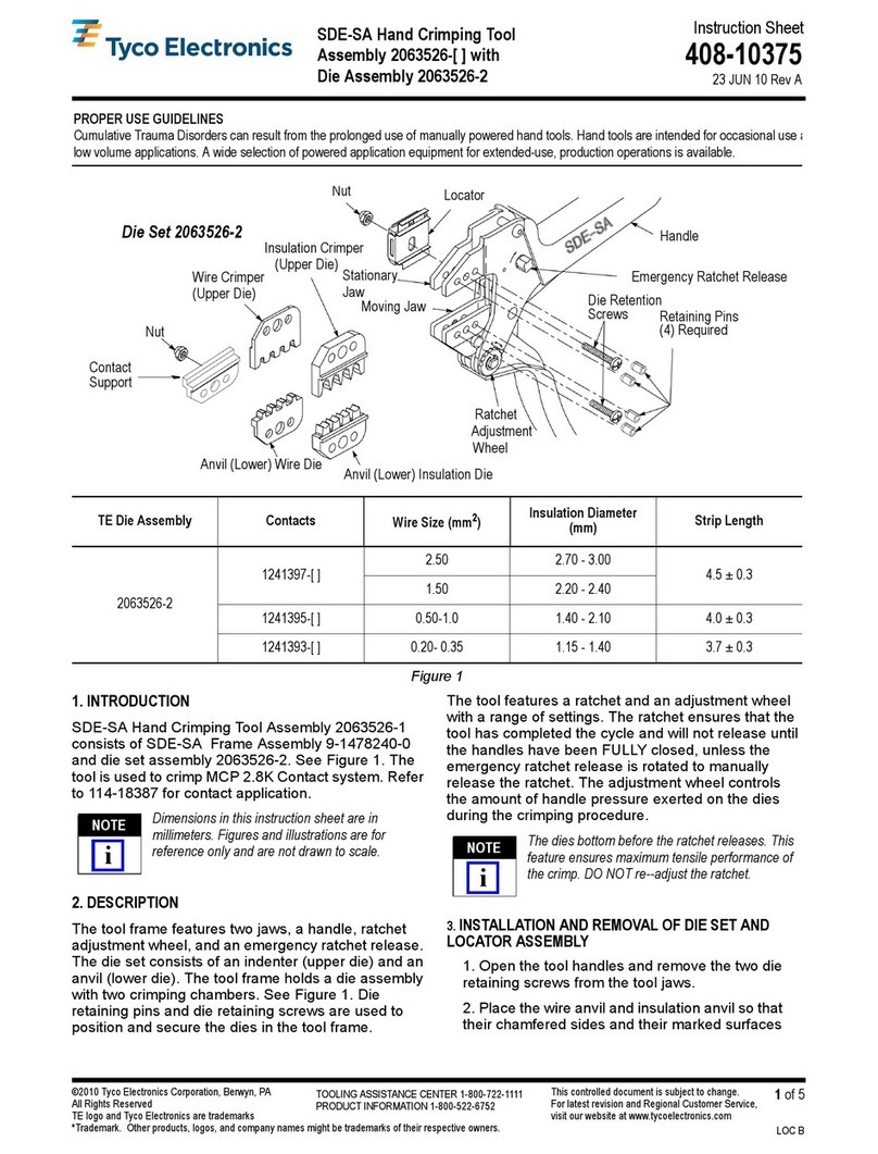
Tyco Electronics SDE-SA 2063526 Series instruction sheet
Cembre
Cembre HT61 Operation and maintenance manual


