Folger Technologies Kossel Rev B User manual


Folger Tech Kossel Rev B User Manual V2 Page 1
Table of Contents
CONTENTS
Introduction ...............................................................................................................................................................................................3
Contact Folger Tech ................................................................................................................................................................................... 3
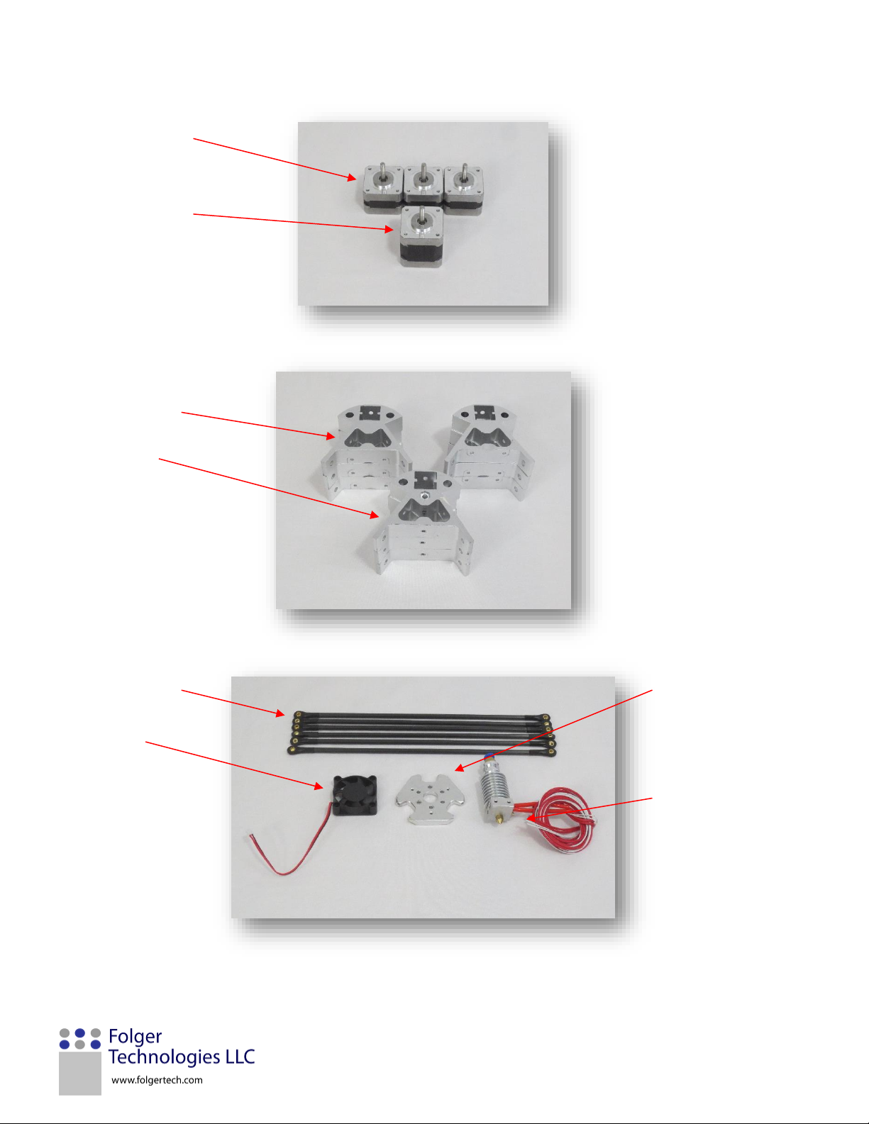
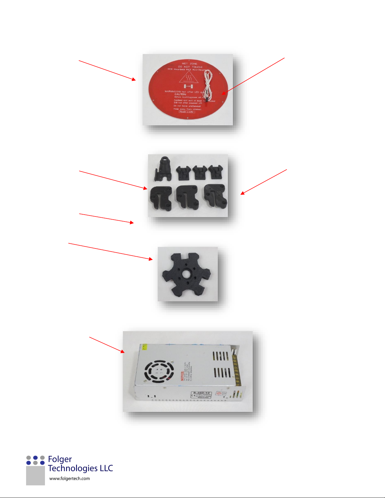
Inventory of Parts ......................................................................................................................................................................................4
Folger Tech Kossel Parts ........................................................................................................................................................................4
Folger Tech Kossel Hardware ................................................................................................................................................................5
Printer Features & Definitions .................................................................................................................................................................11
Printer Assembly ......................................................................................................................................................................................14
1) Assemble the Base ..........................................................................................................................................................................15
2) Assemble the Top ............................................................................................................................................................................ 19
3) Vertical rail installation....................................................................................................................................................................22
4) Assemble the Carriages ...................................................................................................................................................................24
5) Mounting the carriages ...................................................................................................................................................................26
6) Assembly the Effector .....................................................................................................................................................................27
7) Attach the carbon fiber arms ..........................................................................................................................................................29
8) Assemble the Extruder ....................................................................................................................................................................31
9) Mounting the Effector, Endstops, and top ......................................................................................................................................34
10) Mounting Belts ..............................................................................................................................................................................37
11) Assemble and mount the electronics............................................................................................................................................40
12) Wiring the Inductance sensor ....................................................................................................................................................... 44
13) Wiring the heated bed .................................................................................................................................................................. 47
14) Wiring the Printer..........................................................................................................................................................................48
15) Odds and Ends...............................................................................................................................................................................54
Testing and Calibration ............................................................................................................................................................................59
ELECTRONICS Check List ......................................................................................................................................................................59
Software .............................................................................................................................................................................................. 60
Connect to the Printer & Loading Firmware .......................................................................................................................................60
Verify the Endstops .............................................................................................................................................................................62
Verify Motor Direction and Homing ....................................................................................................................................................65
Adjusting Z Height ...............................................................................................................................................................................66

Folger Tech Kossel Rev B User Manual V2 Page 2
Verify the Hot End Temperature .........................................................................................................................................................67
Verify the Extruder ..............................................................................................................................................................................68
Calibrate inductance probe .................................................................................................................................................................68
Software Parameter Setup.......................................................................................................................................................................71
Setting Up A Printer Profile in Cura .....................................................................................................................................................71
Printing Settings .................................................................................................................................................................................. 75
Printing Setting Definitions..................................................................................................................................................................75
Generating G-code using Cura .................................................................................................................................................................82
Step-by-Step Process ........................................................................................................................................................................... 82
Printer Operation.....................................................................................................................................................................................84
Changing Filament ...............................................................................................................................................................................84
Bed Preparation...................................................................................................................................................................................85
Maintenance ............................................................................................................................................................................................86
Check Belt Tension ..............................................................................................................................................................................86
Check for loose screws ........................................................................................................................................................................86
TroubleShooting ...................................................................................................................................................................................... 86
Appendix .................................................................................................................................................................................................. 87
1) Diagnal Rod Assembly .....................................................................................................................................................................87
2) 2004 LCD Screen..............................................................................................................................................................................90
3) Printing from an SD Card .................................................................................................................................................................92
Step-by-step Process ...........................................................................................................................................................................92
4) Ramps 1.4 ........................................................................................................................................................................................ 93

Folger Tech Kossel Rev B User Manual V2 Page 3
INTRODUCTION
Congratulations! If you are looking over this manual it means that you are the proud owner of a Folger Tech Kossel 3D Printer, which
is a powerful tool that can help you unleash your creative spirit.
Our goal as a company is to provide affordable 3D printers to consumers worldwide. On top of this we want everyone’s first printing
experience to be a great one. So this User Manual was assembled to provide guidance in assembling and understanding common
procedures while using our 3D printer. It covers everything from assembly to the maintenance required to keep your printer
performing like new.
We look forward to helping you succeed in the exciting world of 3D printing and giving you everything you need to unlock your
innovation.
CONTACT FOLGER TECH
We understand that manual only covers the basics of your Folger Tech printer, so if at any time you need more assistance, visit our
support page at Folger Tech Support to send us a message and we will be happy to address your question or concern.
DISCLAIMER OF LIABILITY: FOLGER TECHNOLOGIES LLC specifically DISCLAIMS LIABILITY FOR INCIDENTAL OR CONSEQUENTIAL
DAMAGES and assumes no responsibility or liability for any loss or damage suffered by any person as a result of the use or misuse of
any of the information or product. FOLGER TECHNOLOGIES LLC assumes or undertakes NO LIABILITY for any loss or damage suffered
as a result of the use, misuse or reliance on the information and or product. USE AT YOUR OWN RISK: Never leave your printer
unattended. This kit involves working with 110v/220v and should only be done if you are qualified, if you are not, speak to a
qualified electrician.

Folger Tech Kossel Rev B User Manual V2 Page 4
INVENTORY OF PARTS
This section lists the individual parts included in the Folger Tech Kossel 3D Printer Kit. Each item is given a number or
letter identification, which may be referenced later in the manual. Parts are itemized by number and hardware is
itemized by letter. It may be helpful to use these tables as a guide to help you navigate this manual. If you received a
different part then what is in this table, check the Appendix at the end of this manual. That will cover any older bill of
materials.
FOLGER TECH KOSSEL PARTS
Item ID
Quantity
Description
Item ID
Quantity
Description
1
6
AL Bottom Corner
24
3
GT2 20tooth Pulley
2
3
AL Top Corner
25
1
Inductive Probe
3
9
300mm 2020 Beam
26
1
10K Resistor
4
3
700mm 2020 Beam
27
1
15K Resistor
5
3
2600 Stepper Motor
28
6
Bed Mount Spacer
6
3
5800 Stepper Motor
29
1
Spool Mount
7
6
Carbon Fiber Arm
30
1
Electronic Mount
8
1
1.75 Teflon Tube
(Bowden)
31
1
Extruder Mount
9
1
Upper Block
32
2
Power Supply Mount
10
1
1.75 All Metal Hot End
33
3
End Stop Mount
11
1
2mm Push Fit
34
1
Drive Gear
12
1
Round Heat Bed
35
1
40mm Fan
13
1
100K NTC Thermistor
36
1
AC Cord
14
1
MKS Base Board
37
3
2020 Insert
15
5
Stepper Driver
38
1
Filament Sample
16
3
Endstop (Limit Switch)
39
4’
Red 14 AWG Wire
17
1
USB Cable
40
4’
Black 14 AWG Wire
18
1
360W Power Supply
41
3’
Red 22 AWG Wire
19
3
Belt Holder
42
3’
Black 22 AWG Wire
20
3
Roller Carriages
43
1
Long Motor Wire
21
1
Effector
44
3
Short Motor Wire
22
1
Sensor Mount
45
1
3 pin connector pigtail
23
1
GT2 Belt
46
1
Kapton Tape
47
1
Injection Molded Block

Folger Tech Kossel Rev B User Manual V2 Page 5
FOLGER TECH KOSSEL HARDWARE
Item
ID
Total
Supplied
Description
Item ID
Total
Supplied
Description
A
3
M3 Nut
L
4
M4 Large Washer
B
40
M3 Nylock Nut
M
46
M4 T-nut
C
16
M3 T-nut
N
13
M4x8 Screw
D
4
M3 Flat Washer
O
40
M4x10 Screw
E
30
M3x8 Screw
P
10
M5 Nylock Nut
F
18
M3x12 Screw
Q
10
M5x25 Screw
G
24
M3x16 Screw
R
6
F623zz Bearing
H
10
M3x20 Screw
S
4
Belt Tensioner
I
30
M3x25 Screw
T
18
Black Zip Tie
J
6
M3x30 Screw
U
10
Nylon Roller
K
3
M3x45 Screw
V
1
Wire Wrap
3. 300mm 2020
Beam
4. 700mm 2020
Beam
37. 2020 Insert

Folger Tech Kossel Rev B User Manual V2 Page 6
5. 2600 Stepper Motor
6. 5800 Stepper Motor
1. AL Bottom Corner
2. AL Top Corner
7. Carbon Fiber Arm
21. AL Effector
(optional add-on
feature not included
with stock kit)
35. 40mm Fan
10. All Metal Hot end

Folger Tech Kossel Rev B User Manual V2 Page 7
47. Injection Mold Block
24. GT2 20Tooth Pulley
9. Upper Block
Q. F623zz Bearing
34. Drive Gear
11. 2mm Push Fit
15. Stepper Driver
16. Endstop
14. MKS Base Board
(MKS board is an add-on
feature not included in
stock kit)
Stepper Motor
Ramps 1.4 Board
Arduino Mega

Folger Tech Kossel Rev B User Manual V2 Page 8
12. Round Hot Bed
13. 100k NTC Thermisor
22. Sensor Mount
19. Belt Holder
20. Roller Carriages
Printed Effector
18. 360W Power Supply

Folger Tech Kossel Rev B User Manual V2 Page 9
36. AC Cord
V. Wire Wrap
23. GT2 Belt
45. 3 Pin Connector
39-40. 14 AWG Wire
25. Inductance Probe
41-42. 22 AWG Wire
26-27. Resistors

Folger Tech Kossel Rev B User Manual V2 Page 10
Hardware Kit
8. 1.75 Teflon Tube
46. Kapton Tape
33. Endstop Mount
31. Extruder Mount
32 Power Supply Mount
28. Bed Mount Spacer
30. Electronic Mount

Folger Tech Kossel Rev B User Manual V2 Page 11
PRINTER FEATURES & DEFINITIONS
The figure below shows the features of the Folger Tech Kossel 3D printer. You can reference this graphic for clarification of printer
parts mentioned in this manual.
Printer
Bed
Effector
(Hot end & Nozzle)
Bowden
Tube
Filament
Spool
Power Supply
Extruder
Tower
Carriage
Inductance
sensor
Belt

Folger Tech Kossel Rev B User Manual V2 Page 12
Extruder
The extruder pushes the filament from the spool into the hot end of the effector. Components of the extruder:
Drive Gear (Red), feeds the filament to the hot end
Extruder Lever (Blue), applies force so the drive gear can grip the filament
Bowden Tube push fitting (Green), attaches the Teflon bowden tube to the extruder.
Bowden Tube (Teflon Tube)
The Bowden Tube is the small tube that runs from the extruder to the hot end.
Nozzle
The nozzle is the brass fitting below the heater block that the plastic extrudes from.

Folger Tech Kossel Rev B User Manual V2 Page 13
Hot end
The hot end melts the filament as it gets pushed through the Bowden Tube by the Extruder. It is comprised of the following
parts:
X, Y, Z Towers
Looking at the front of the printer (facing the back of the extruder), the left tower is the X, the right tower is the Y, and the back
tower is the Z. These designations are used when leveling the bed and during troubleshooting procedures.
Carriage
Attached to each rail is a carriage, each carriage connects to the effector using two support arms. The position of the three
carriages together controls the absolute position of the effector.
Effector
The effector holds the hot end and moves about the printing area. It is connected to the three carriages by the support arms.
Power Supply
The power supply is what takes the 120 AC from the wall and converts it into 12v DC.
Heat Sink
Hot end Fan
Inductance
sensor
Thermistor
Heater Core
Heater Block
Nozzle

Folger Tech Kossel Rev B User Manual V2 Page 14
PRINTER ASSEMBLY
Construction of a Folger Tech Kossel 3D Printer is broken into 15 individual phases and sub-assemblies. The table
below shows the different phases required to complete your 3D printer.
Phase
Assembly Description
Page
1
Assemble the base
14
2
Assemble the Top
18
3
Vertical Rail Installation
21
4
Assemble The Carriages
23
5
Mount the Carriages
25
6
Assemble The effector
26
7
Attach Carbon Fiber Rods
28
8
Assembly The Extruder
30
9
Mount the Extruder, Endstops, and Top
33
10
Mounting Belts
36
11
Assemble and Mount Electronics
39
12
Wiring the Inductance Sensor
43
13
Wiring the Heated Bed
46
14
Wiring the Printer
48
15
Odds and Ends
54

Folger Tech Kossel Rev B User Manual V2 Page 15
1) ASSEMBLE THE BASE
In this section you will be building the base frame of the Kossel 3D Printer.
You will need:
Item ID
Quantity
Description
1
3
A Bottom Corner
3
3
300mm 2020 beams
5
6
2600 Stepper Motor
24
3
GT2 20tooth Pulley
E
12
M3x8mm Screw
O
24
M4x10mm Screw
M
24
M4 T-nut
1. Insert the GT2 pulley onto the stepper motor
(you may need to loosen the set screw on the
pulley). There should be a 2mm gap between
the tip of the motor shaft and the end of the
pulley. Once the pulley is positioned correctly,
tighten both set screws.

Folger Tech Kossel Rev B User Manual V2 Page 16
2. Position the Aluminum corner so the two
screw holes line up with the stepper mounting
holes (see picture). Use two M3x8mm screws
to secure the corner to the motor. Repeat this
for the second aluminum corner that mounts
to the same stepper motor. Note: The
connector for the stepper should be pointing
towards the left or the right. This will make
wiring easier later on.
3. Take an M4x10mm screw and a M4 T-nut,
insert the screw into one of the holes on the
side of the aluminum corner. Attach the T-nut
to the other side. Do not tighten the T-nut
down, these will be inserted into the 2020
beams at a later step. Repeat this process for
the other 7 holes (see picture for locations).
Make sure the taped edged side of the T-nut
faces away from the corner.
4. Repeat steps 1- 3 for the other two corners.

Folger Tech Kossel Rev B User Manual V2 Page 17
5. Take one of the 300mm 2020 beams and place
it over two of the T-nuts to the side of the
motor. Then tighten the two screws and the T-
nuts will lock into the 2020 beam. Make sure
the beam is tight into the corner (see picture).
Repeat this step for the other 2020 beam on
that side.
6. Repeat step 5 for the other two corners. Make
sure the 2020 Beams are located on the same
side of the corner.
7. Line up the three corner pieces so they form a
triangle. Slide each corner towards each other
until all the 2020 beams are tight into the
other corners. Make sure the T-nuts are
slotted into their respective beam. Tighten the
screws and lock the T-nuts into place.

Folger Tech Kossel Rev B User Manual V2 Page 18
8. Double check all of the screws to make sure
they are tight and that the base is locked
tightly together.

Folger Tech Kossel Rev B User Manual V2 Page 19
2) ASSEMBLE THE TOP
In this section, the top of the printer will be assembled.
You will need:
Item ID
Quantity
Description
2
3
Al Top Corner
3
3
300mm 2020 beams
R
6
F623zz Bearing
B
3
M3 Nylock
I
3
M3x25mm Screw
O
12
M4x10mm Screw
N
3
M4x8mm Screw
M
15
M4 T-nut
1. Insert a M4x10mm screw into one of the side
holes on the aluminum corner and screw a M4
T-nut onto the other end. Repeat this for the
three holes on the corner piece.
Table of contents
Other Folger Technologies 3D Printer manuals