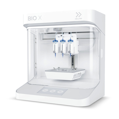
Cellink BIO X User manual

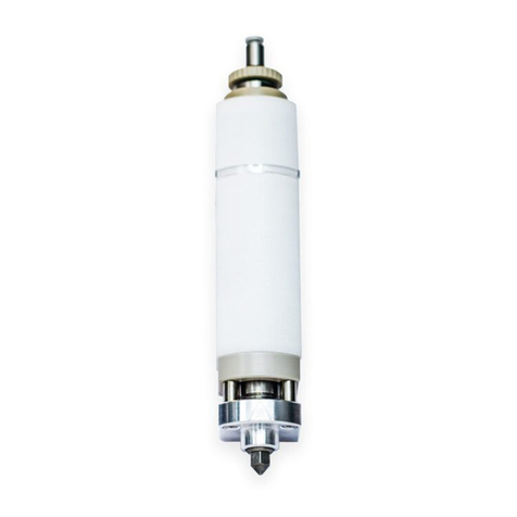
BIO X Temperature-controlled Printhead
User Manual


Contents
1. Package contents
2. Technical specicaons
3. Safety informaon
3.1 BIO X system warnings
3.2 Temperature-controlled Printhead warnings
4. Geng started
4.1 Unpacking and installaon
4.2 Oponal: Aaching nozzle/needle insulator
4.3 Raising and lowering the printhead
4.4 Loading the bioink cartridge
4.5 Removing the printhead
4.6 Your rst bioprint
5. Temperature- controlled Printhead opmizaon
6. Relevant G-code commands
7. Frequently asked quesons
8. Maintenance
Appendix A: Consumables
Support informaon
1
3
7
8
8
9
11
12
13
15
18
19
27
31
33
37
39
46


1
Package contents
01

2
01 Package contents
Item
Temperature-controlled Printhead
Locking screw
Part number
000000020346
000000020106
Quanty
1
1

3
Technical specicaons
02

4
• Compable with 3-mL plasc cartridge.
• Dimensions (height x width x depth): 90 x 46 x 58 mm.
• Weight: 183 g.
• Maximum pressure: 700 kPa.
• Material composion:
• External surfaces: Aluminum.
• Internal surfaces: Aluminum.
• Recommended operang temperature: 20-23 degrees Celsius.
NOTE: We recommend operang BIO X in temperatures between 20 and 23 degrees. In normal operang
condions, the chamber temperature of the BIO X will rise 2-3 degrees above the ambient temperature.
• Running temperature (in recommended condions): 26-32 degrees.
• Heang capacity and rate:
• Total heang range: 65 degrees.
• Heang rate: Room temperature-65 degrees (10 minutes).
• Cooling capacity and rate:
• Minimum temperature: 17 degrees below chamber temperature.
• Cooling rate: Room temperature-Δ17 degrees (15 minutes).
• Build volume (X, Y, Z): 128 x 85 x (80–A) mm; A represents p length.
02 Technical specicaons

5
Figure 1: Theorecal maximum build volume shown from the top and side view when using the Temperature-controlled Printhead.
Exact build volume depends on the cartridge’s posion in the printhead and the nozzle/needle used. Build volume may be lower when
combining the Temperature-controlled Printhead with a printhead that restricts printbox movement. Please consult the printhead
manual for the printheads being used for specic limitaons.
Top View Front View Isometric View
02 Technical specicaons

6
02 Technical specicaons
Table 1: Theorecal build volume based on common p lengths. Actual volume may vary based on build plate thickness, size,
shape, level, cartridge posion and nozzle ghtness. X, Y and Z are measured from the front le corner of the printbed.
Tip Type Tip Length Nozzle/
Needle Length X Y Z Build Volume
Conical 3.2 cm 3.2 cm 12.7 cm 9.36 cm 4.8 cm 570 cm3
Blunt 2.4 cm 0.635 cm 12.7 cm 9.36 cm 5.6 cm 665 cm3
Blunt 3.0 cm 1.27 cm 12.7 cm 9.36 cm 5.00 cm 594 cm3
Blunt 4.3 cm 2.54 cm 12.7 cm 9.36 cm 3.70 cm 440 cm3
Micron-S 1.9 cm 1.9 cm 12.7 cm 9.36 cm 6.12 cm 727 cm3

7
Safety informaon
03

8
03 Safety informaon
3.1 BIO X system warnings
• Please consult the BIO X manual for BIO X-specic warnings and safety procedures.
3.2 Temperature-controlled Printhead warnings
• DO NOT clean the printhead by submerging it in liquid or using excessive spraying. Liquid inside the printhead can damage the circuitry and
motor.
• The LED on the printhead will turn yellow to indicate a warm printhead and red to indicate a hot printhead. Do not touch the printhead when
the LED is red. Touching a hot printhead risks serious injury.
• DO NOT manually move the printhead mount. Moving the printhead mount manually will damage the motor. If the mount needs to be moved,
place the printhead in the loading posion described in the Geng Started secon.
• The Temperature-controlled Printhead can be hot to the touch aer use. DO NOT touch the foils when the printhead is heang or cooling.
• DO NOT manually move the printhead mount. Moving the printhead mount manually will damage the motor. If the mount needs to be moved,
place the printhead in the loading posion described in the Geng Started secon.
• Use the proper method to load and unload the EMD Printhead onto the BIO X printhead mounts. Instrucons are outlined in the Geng
Started secon. While loaded on the BIO X, do not pull or push the printhead with excessive force, especially when the BIO X system is turned
on. Doing so will damage the motor and its guides.
• DO NOT use a jerking moon to remove the printhead. Using a jerking moon risks hing and damaging the HEPA lter.
• DO NOT place ngers on the printhead while it is in moon. Users risk serious, permanent injury if ngers are caught between the printhead
base and the motor arm.
• The cooling fan of the Temperature-controlled Printhead is exposed to allow for heat dissipaon. DO NOT put ngers or other objects into the
fan while the printhead is in operaon. Doing so risks injury and damage to the printhead.
cooling.

9
Geng started
04

10
04 Geng started
NOTE: The prinng parameters displayed on this manual might not be accurate for your specic protocol. For recommended
parameters please consult the documentaon for the bioink being used.
1
2
3
4
5
6
Figure 2: Temperature-controlled Printhead components.
1. Cardge Adapter
2. Cardge
3. Printhead Body
4. Fan
5. Heat Sink
6. Locking Screw

11
04 Geng started
Unpacking and installaon
• Open the package. Remove the Temperature-controlled printhead.
• Check for locking screw (Figure 2).
• Check the fan and heatsink for any debris.
• Oponal: Aach needle/nozzle insulator:
• Ensure that the nozzle/needle insulator has the right gauge for the diameter of the nozzle/needle being used.
• Align the insulator, screws and nozzle (Figure 3A).
• Insert the collar of the insulator into the Temperature-controlled Printhead.
• Tighten the screws to secure the insulator to the printhead (Figure 3B).
Figure 3: Aaching the nozzle/needle insulator to the Temperature-controlled Printhead.
AB

12
04 Geng started
• To install the printhead, stabilize the boom of the printhead mount with one hand to avoid straining the motor. Align the printhead above the
desired printhead mount and push downward using your opposite hand (Figure 4).
Figure 4: Inserng the Temperature-controlled Printhead into the BIO X system.
AB C D

13
04 Geng started
Raising and lowering the printhead
• On the user interface, navigate to the Ulies menu and then go to the Tools submenu.
• Lower the desired printhead mount into the acve or loading posion by pressing the down arrow (Figure 5).
• Press the up arrow to return the printhead to the nonacve posion.
Figure 5: Lowering the printhead into the acve posion.

14
04 Geng started
Preheang or precooling the Temperature-controlled Printhead
• Set a temperature in the BIO X soware using the Ulies menu and Tools submenu. When cooling, the
operang temperature range of the Temperature-controlled Printhead has a maximum of 17 degrees below the
chamber temperature; when heang, the maximum temperature is 65 degrees (Figure 6).
• Wait for the the Temperature-controlled Printhead to reach the set temperature.
Figure 6: Preset temperature for the Temperature-controlled Printhead.
NOTE: We recommend precooling or preheang
your bioink in the cartridge outside the printhead
in an incubator, water bath or refrigerator before
use. If using a water bath, ensure the cartridge is
dry before pung it in the printhead.

15
04 Geng started
Loading the bioink cartridge
• Fill a cartridge with bioink or use a prelled cartridge.
• Remove the p cap (Figure 7A). Aach a nozzle (Figure 7B). Remove the end cap (Figure 7C).
Figure 7: Preparing a prelled bioink cartridge.
AB C

16
04 Geng started
Figure 8: Aaching the air adapter to the cartridge.
• Align the cartridge adapter to the loaded cartridge (Figure 8A). Twist unl secure (Figure 8B).
AB
Other manuals for BIO X
3
This manual suits for next models
1
Table of contents
Other Cellink 3D Printer manuals