FOLKNOLL DISABLED REFUGE EVC User manual
Folknoll Group Ltd.
File:DR 7700-000 SM7 V100 Refuge EVC Manual 3-Zone.Docx E+EO (c) 2018 Folknoll Group Ltd
DISABLED REFUGE EVC
3-ZONE REFUGE EVC SYSTEM MANUAL

DISABLED REFUGE EVC
PAGE i
3-ZONE REFUGE EVC SYSTEM MANUAL V1.00
File:DR 7700-000 SM7 V100 Refuge EVC Manual 3-Zone.Docx E+EO (c) 2018 Folknoll Group Ltd
PAGE i
ISSUE
VERSION
DATE
DESCRIPTION
V1.00
02.11.2018
Original
CONTENTS
1INTRODUCTION...........................................................................................................................................................1
1.1 WHAT IS A DISABLED REFUGE EVC SYSTEM .......................................................................................................... 1
1.2 FOLKNOLL 3-ZONE REFUGE EVC............................................................................................................................ 1
1.1.1 Fire-Resistant Cabling ....................................................................................................................................1
1.1.2 Choice of Outstations ....................................................................................................................................1
1.1.3 3-Zone Master Station...................................................................................................................................1
1.1.4 3-Zone Controller with Battery Backed PSU ..................................................................................................1
1.1.5 Audio Path Testing and Reporting .................................................................................................................1
1.1.6 Third Party Interfaces ....................................................................................................................................1
1.2 ABOUT US.............................................................................................................................................................. 2
23-ZONE REFUGE EVC INSTALLATION ...........................................................................................................................3
2.1 3-ZONE SYSTEM CABLING RULES ..........................................................................................................................3
33-ZONE REFUGE EVC CONNECTIONS........................................................................................................................... 4
3.1 3-ZONE OUTSTATION CONNECTION ..................................................................................................................... 4
3.2 3-ZONE OUTSTATION WITH LOOP.........................................................................................................................5
3.3 3-ZONE MASTER STATION CONNECTION..............................................................................................................6
43-ZONE REFUGE EVC COMMISSIONING ......................................................................................................................7
4.1.1 System Controller Addressing........................................................................................................................ 7
4.1.2 Fault Monitoring............................................................................................................................................7
4.1.3 Master Station Controls Enable..................................................................................................................... 7
4.1.4 Initial Power Up ............................................................................................................................................. 8
4.1.5 Outstation Configuration...............................................................................................................................8
4.1.6 Volume and Microphone Gain Adjustment ...................................................................................................8
53-ZONE REFUGE MASTER OPERATION ........................................................................................................................9
5.1 ENABLE THE MASTER STATION CONTROLS...........................................................................................................9
5.2 INCOMING CALLS ................................................................................................................................................10
5.2.1 To Accept an Incoming Call from an Outstation ..........................................................................................10
5.2.2 To Talk to a User..........................................................................................................................................10
5.2.3 To Cancel an Incoming Call from an Outstation ..........................................................................................10
5.3 OUTGOING CALLS................................................................................................................................................ 10
5.3.1 To Make an Outgoing Call to an Outstation ................................................................................................10
5.3.2 To Talk to a User..........................................................................................................................................10
5.3.3 To Cancel an Outgoing call........................................................................................................................... 11
5.4 ALL CALLS AND ANNOUNCEMENTS..................................................................................................................... 11
5.4.1 To Make an All Call ...................................................................................................................................... 11
5.4.2 To Cancel an All Call.....................................................................................................................................11
6OUTSTATION OPERATION .........................................................................................................................................12
6.1 CALLS TO THE OPERATOR.................................................................................................................................... 12
6.1.1 To make an Outgoing Call to an Operator ...................................................................................................12
6.1.2 To Cancel an Outgoing Call .......................................................................................................................... 12
6.2 CALLS FROM THE OPERATOR ..............................................................................................................................12
6.2.1 To Accept an Incoming Call from an Operator............................................................................................. 12
6.2.2 To Cancel an Incoming Call .......................................................................................................................... 12
6.3 ALL CALLS AND ANNOUNCEMENTS.....................................................................................................................13
73- ZONE REFUGE EVC FAULTS.................................................................................................................................... 14

DISABLED REFUGE EVC
PAGE ii
3-ZONE REFUGE EVC SYSTEM MANUAL V1.00
File:DR 7700-000 SM7 V100 Refuge EVC Manual 3-Zone.Docx E+EO (c) 2018 Folknoll Group Ltd
PAGE ii
7.1 AUTOMATIC SYSTEM TEST .................................................................................................................................. 14
7.2 AUDIO PATH TEST TRIGGERED MANUALLY.........................................................................................................14
7.3 AUDIO PATH TEST TRIGGERED EXTERNALLY .......................................................................................................14
7.4 FAULT INDICATIONS............................................................................................................................................14
7.4.1 Mains Power Fault....................................................................................................................................... 15
7.4.2 Master Station Disabled .............................................................................................................................. 15
7.4.3 Audio Path Fault ..........................................................................................................................................15
83-ZONE REFUGE EVC MAINTENANCE........................................................................................................................ 16
8.1 ROUTINE MAINTENANCE ....................................................................................................................................16
8.1.1 Standby Batteries ........................................................................................................................................ 16
8.2 VISUAL INSPECTION ............................................................................................................................................ 16
8.2.1 Outstations ..................................................................................................................................................16
8.2.2 Master Station ............................................................................................................................................. 16
8.2.3 Controller / PSU / Cables ............................................................................................................................. 17
8.3 FUNCTIONAL TESTING......................................................................................................................................... 17
8.3.1 User Call Check ............................................................................................................................................ 17
8.3.2 Operator Call Check.....................................................................................................................................17
8.3.3 All Call Check................................................................................................................................................ 17
8.3.4 Standby Operation Test............................................................................................................................... 17
8.3.5 Standby Time Test .......................................................................................................................................18
8.3.6 Audio Path Test Check .................................................................................................................................18
8.3.7 Automatic Audio Path Testing ..................................................................................................................... 18
9APPENDIX A FIRETUF CABLES....................................................................................................................................19
FIGURES
Figure 1 Typical 3-Zone System ..............................................................................................................3
Figure 2 Typical 3-Zone Outstation Connection .....................................................................................4
Figure 3 Typical 3-Zone Outstation with Induction Loop Connection....................................................5
Figure 4 Typical 3-Zone Master Connection ...........................................................................................6
Figure 5 Master Station PCB ...................................................................................................................7
Figure 6 Master Station Panel.................................................................................................................9
Figure 7 Example Outstations...............................................................................................................12

DISABLED REFUGE EVC
PAGE 1
3-ZONE REFUGE EVC SYSTEM MANUAL V1.00
File:DR 7700-000 SM7 V100 Refuge EVC Manual 3-Zone.Docx E+EO (c) 2018 Folknoll Group Ltd
PAGE 1
1INTRODUCTION
This document is the Folknoll Group Ltd 3-Zone Refuge EVC System Manual.
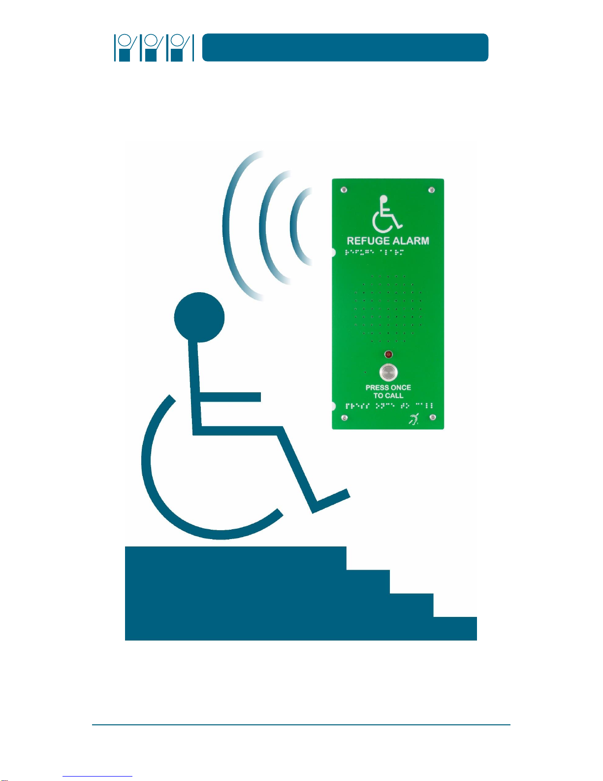
1.1 WHAT IS A DISABLED REFUGE EVC SYSTEM
A disabled refuge is a relatively safe area where people can gather in emergencies to await rescue. A
disabled refuge EVC is an emergency voice communication system that enables persons in a refuge to
communicate with building management in the event of an emergency. The purpose of the refuge
EVC is to help coordinate rescue by providing information, instruction and reassurance to refuge users.
1.2 FOLKNOLL 3-ZONE REFUGE EVC
For sites with 3 or less refuge areas, we offer our cost-effective 3-zone refuge EVC system. Installation
costs are reduced without compromising functionality by building the system controller and a battery
backed PSU into single steel enclosure.
1.1.1 Fire-Resistant Cabling
Terminals are provided within all equipment for cable termination and space is allowed for glanding
of larger fire-resistant cable types to comply with BS requirements.
1.1.2 Choice of Outstations
Any of our range of refuge outstations can be used in conjunction with our 3-zone refuge systems,
offering a range of vandal resistance, IP rating and DDA compatibility to suit your site.
1.1.3 3-Zone Master Station
Our 3-zone master station is a specially designed minimalist panel for our 3-zone EVC with individual
illuminated buttons for each outstation and input for remote enable.
1.1.4 3-Zone Controller with Battery Backed PSU
Our 3-zone controller and battery backed system PSU is built into a single steel enclosure. The system
is usually supplied with backup batteries capable of providing at least 24 hours of quiescent operation
and 30 minutes of alarm operation.
1.1.5 Audio Path Testing and Reporting
Folknoll Disabled Refuge EVC systems offer audio path monitoring and reporting. Audio tones are
generated by outstation speakers and detected by outstation microphones. This signal received is
verified to test the electrical and mechanical audio path. If a fault is detected it is reported on the
master station.
Audio path testing can be triggered by external devices e.g. timers or BMS. A fault output is available
to activate external devices or management systems.
1.1.6 Third Party Interfaces
Folknoll offer closing contact, serial and IP interfaces for integration with third-party systems, e.g.
BMS, alarm gathering, etc. helping to provide an integrated solution for your needs.

DISABLED REFUGE EVC
PAGE 2
3-ZONE REFUGE EVC SYSTEM MANUAL V1.00
File:DR 7700-000 SM7 V100 Refuge EVC Manual 3-Zone.Docx E+EO (c) 2018 Folknoll Group Ltd
PAGE 2
1.2 ABOUT US
We are a UK based company with over 30 years of design and manufacturing experience. All of our
products and systems are designed for toughness, reliability, easy installation, simple configuration,
straightforward operation and low maintenance. As original manufacturer, all of our product ranges
can be customised to suit your application. Including custom engraved panels, additional features and
special systems.
Please contact us for further information about our wide range of products and services and find out
how we can provide a solution for you.

DISABLED REFUGE EVC
PAGE 3
3-ZONE REFUGE EVC SYSTEM MANUAL V1.00
File:DR 7700-000 SM7 V100 Refuge EVC Manual 3-Zone.Docx E+EO (c) 2018 Folknoll Group Ltd
PAGE 3
23-ZONE REFUGE EVC INSTALLATION
Mount equipment and pull the required cables, please refer your system drawings or the drawing
below as appropriate. Terminate the cables but do not power up, (please refer to section 3 3-Zone
Refuge EVC Connections).
Figure 1 Typical 3-Zone System
A refuge EVC is usually part of a fire safety system and must be installed in accordance with current
regulations and standards.
FIRE RESISTANT CABLING MAY BE REQUIRED E.G. FT120 OR FIRETUFDATA, PLEASE REFER TO
SECTION 9 APPENDIX A FIRETUF CABLES
In a standard 3-Zone system there is a single controller with battery backed PSU, which provides
control and power to the entire system. All devices are “star” wired to the controller, the controller is
connected to mains. Mains should be by a competent and authorised electrician according to local
and site regulations.
2.1 3-ZONE SYSTEM CABLING RULES
•Cables to outstations without induction loops should be 2-pair 22AWG STP or above
•Cables to outstations with induction loops should be 4-pair 22AWG STP or above
•Cables to the master station should be 4 pair 22AWG STP or above
•No termination resistors are required
•Assuming FIRETUFdata cable is used the maximum length of cable between each outstation
•and the system controller is 200m
•Assuming FIRETUFdata cable is used the maximum length of cable between the master station
and the system controller is 200m
DISABLED REFUGE EVC
PAGE 4
3-ZONE REFUGE EVC SYSTEM MANUAL V1.00
File:DR 7700-000 SM7 V100 Refuge EVC Manual 3-Zone.Docx E+EO (c) 2018 Folknoll Group Ltd
PAGE 4
33-ZONE REFUGE EVC CONNECTIONS
All connection is via terminal block located within the equipment. Folknoll’s design has allowed
sufficient room for glands for larger fire-resistant cables types to comply with BS requirements.
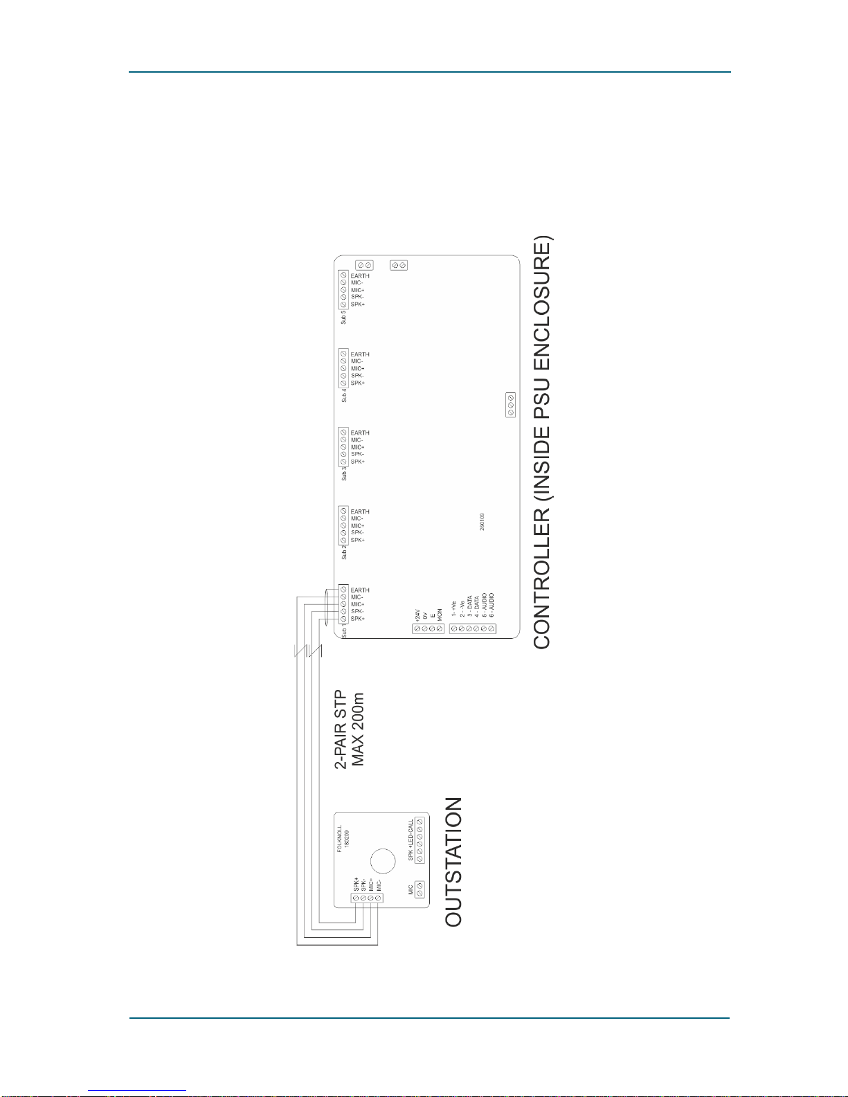
3.1 3-ZONE OUTSTATION CONNECTION
Figure 2 Typical 3-Zone Outstation Connection

DISABLED REFUGE EVC
PAGE 5
3-ZONE REFUGE EVC SYSTEM MANUAL V1.00
File:DR 7700-000 SM7 V100 Refuge EVC Manual 3-Zone.Docx E+EO (c) 2018 Folknoll Group Ltd
PAGE 5
3.2 3-ZONE OUTSTATION WITH LOOP
Figure 3 Typical 3-Zone Outstation with Induction Loop Connection
USUALLY 4-PAIR CABLE IS USED WITH LOOP POWER PAIRS DOUBLED UP
DISABLED REFUGE EVC
PAGE 6
3-ZONE REFUGE EVC SYSTEM MANUAL V1.00
File:DR 7700-000 SM7 V100 Refuge EVC Manual 3-Zone.Docx E+EO (c) 2018 Folknoll Group Ltd
PAGE 6
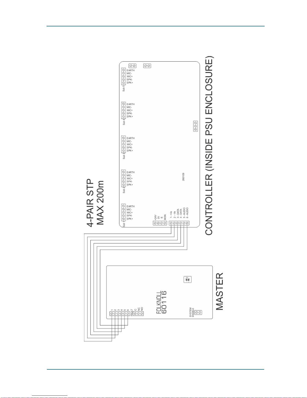
3.3 3-ZONE MASTER STATION CONNECTION
Figure 4 Typical 3-Zone Master Connection
USUALLY 4-PAIR CABLE IS USED WITH POWER PAIRS DOUBLED UP
DISABLED REFUGE EVC
PAGE 7
3-ZONE REFUGE EVC SYSTEM MANUAL V1.00
File:DR 7700-000 SM7 V100 Refuge EVC Manual 3-Zone.Docx E+EO (c) 2018 Folknoll Group Ltd
PAGE 7
43-ZONE REFUGE EVC COMMISSIONING
4.1.1 System Controller Addressing
The 3-zone system only has one controller and its addressing is factory set, no commissioning
required.
4.1.2 Fault Monitoring
The 3-zone master station is fitted with a fault monitoring circuit. Fault monitoring is factory disabled
for shipping and installation. After the Disabled Refuge EVC system is installed and ready to power up,
fault monitoring should be enabled by setting both PCB dip switches to on. The monitoring circuit will
report power fail until power is applied, press the MUTE button to silence the alarm.
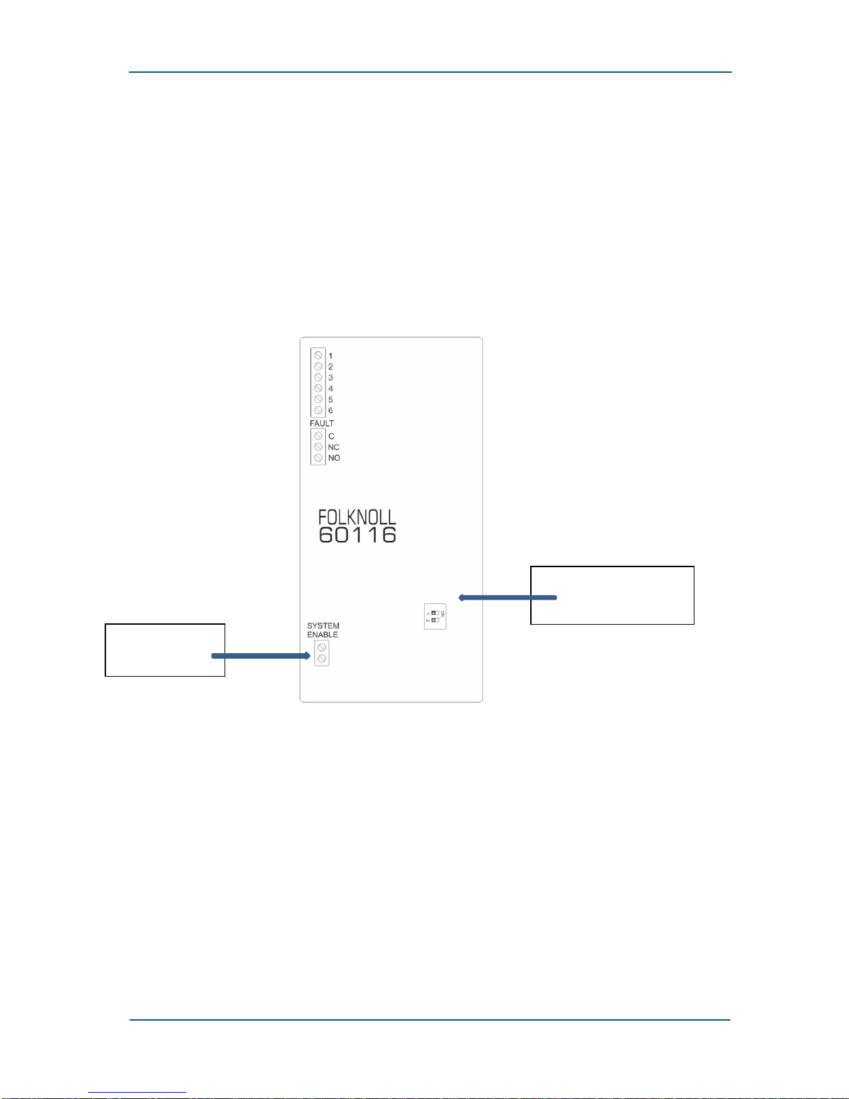
Figure 5 Master Station PCB
4.1.3 Master Station Controls Enable
The master station is supplied fitted with a link between the SYSTEM ENABLE terminals to enable the
master station controls.
If an external enable, e.g. from a fire alarm system, is required this link is removed and the external
system connected to these terminals. Before commissioning this system, the third-party enable must
be activated or overridden.
Power fault monitoring
dip switch
System enable
terminals

DISABLED REFUGE EVC
PAGE 8
3-ZONE REFUGE EVC SYSTEM MANUAL V1.00
File:DR 7700-000 SM7 V100 Refuge EVC Manual 3-Zone.Docx E+EO (c) 2018 Folknoll Group Ltd
PAGE 8
4.1.4 Initial Power Up
Please refer to section 5 3-Zone Refuge Master Operation to familiarise yourself with the layout of the
master station panel.
When ready, power up the system. The master station power LED will illuminate and it will report a
fault until configuration has been completed, see section 4.1.5 Outstation Configuration below.
4.1.5 Outstation Configuration
The system is configured by pressing the TEST button. When the fault LED stops flashing and the
sounder is silent the system is fully configured. No further commissioning is required.
4.1.6 Volume and Microphone Gain Adjustment
Outstation microphone gain and speaker volume are factory set and should not be adjusted during
commissioning. If adjustment is required please contact Folknoll.
DISABLED REFUGE EVC
PAGE 9
3-ZONE REFUGE EVC SYSTEM MANUAL V1.00
File:DR 7700-000 SM7 V100 Refuge EVC Manual 3-Zone.Docx E+EO (c) 2018 Folknoll Group Ltd
PAGE 9
53-ZONE REFUGE MASTER OPERATION
For the purposes of this manual we will refer to the person or persons using the system from a refuge
area as the user, and the persons operating the system from the master station as the operator.
THIS SYSTEM SHOULD BE OPERATED IN ACCORDANCE TO THE RELEVANT STANDARDS AND
REGULATIONS
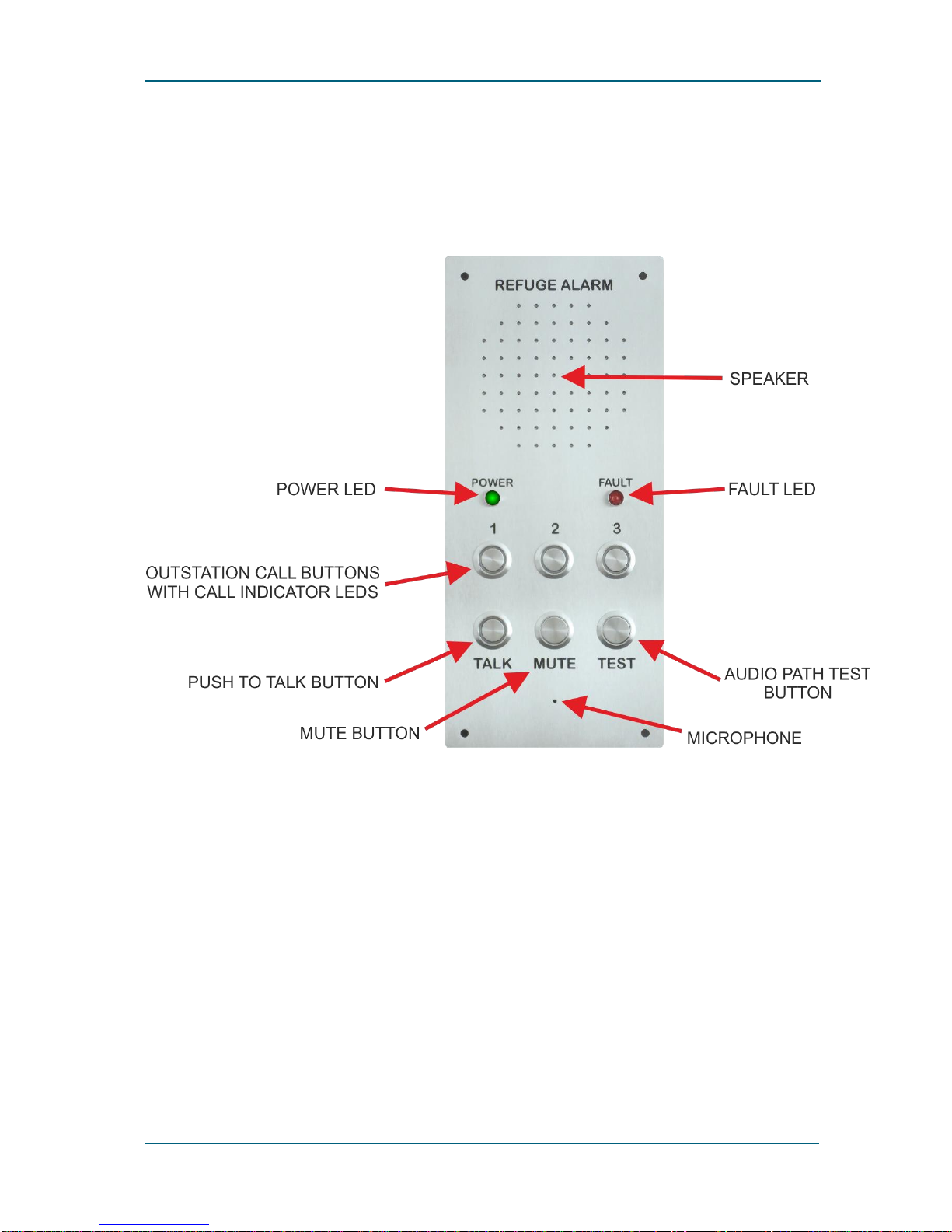
Figure 6 Master Station Panel
5.1 ENABLE THE MASTER STATION CONTROLS
Ensure the master station controls are enabled. If fitted, override the third-party system enable. This
will should happen automatically in the event of a fire or other emergency. If required by local
procedures ensure that the master station controls are disabled after use.

DISABLED REFUGE EVC
PAGE 10
3-ZONE REFUGE EVC SYSTEM MANUAL V1.00
File:DR 7700-000 SM7 V100 Refuge EVC Manual 3-Zone.Docx E+EO (c) 2018 Folknoll Group Ltd
PAGE 10
5.2 INCOMING CALLS
An outstation user initiates a call by pressing CALL button on an outstation.
When a call is initiated
•The master station sounder will sound
•The button on the master station corresponding to the calling outstation i.e. 1, 2or 3, will
flash
5.2.1 To Accept an Incoming Call from an Outstation
Operators accept the incoming call by pressing the flashing button corresponding to the calling
outstation.
When a call is accepted:
•The master station sounder will cease
•The button on the master station corresponding to the calling outstation will be illuminated
(stop flashing)
•The operator will be able to hear the user
5.2.2 To Talk to a User
This system is a push to talk (PTT) system. To talk to a user the operator must press and hold the TALK
button. Whilst the TALK button is held the operator will not be able to hear the user.
5.2.3 To Cancel an Incoming Call from an Outstation
To cancel an incoming call the operator should press the illuminated button corresponding to the
calling outstation.
After the call is cancelled:
•The button on the master station corresponding to the calling outstation will no longer be
illuminated
•The operator will not be able to hear the user
5.3 OUTGOING CALLS
5.3.1 To Make an Outgoing Call to an Outstation
To call an outstation the operator presses the button corresponding to the required outstation i.e. 1
2or 3.
Once the button has been pressed:
•The button on the master station corresponding to the outstation called will be illuminated
•The operator will be able to hear the user
5.3.2 To Talk to a User
This system is a push to talk (PTT) system. To talk to a user the operator must press and hold the TALK
button. Whilst the TALK button is held the operator will not be able to hear the user.

DISABLED REFUGE EVC
PAGE 11
3-ZONE REFUGE EVC SYSTEM MANUAL V1.00
File:DR 7700-000 SM7 V100 Refuge EVC Manual 3-Zone.Docx E+EO (c) 2018 Folknoll Group Ltd
PAGE 11
IF AN OPERATOR INITIATES A CALL, THE OPERATOR MAY ANNOUNCE THEIR PRESENCE. E.G. SAY
“HI THIS THE EVC OPERATOR CALLING” SO THAT THE USER KNOWS A CALL HAS BEEN MADE AND
CAN RESPOND
5.3.3 To Cancel an Outgoing call
To cancel an outgoing call the operator should press the illuminated button corresponding to the
called outstation.
After the call is cancelled:
•The button on the master station corresponding to the outstation will no longer be illuminated
•The operator will not be able to hear the user
5.4 ALL CALLS AND ANNOUNCEMENTS
An “All Call” is an announcement that can be heard by all users simultaneously, e.g. “the Fire Bridged
has arrived please standby”.
5.4.1 To Make an All Call
The operator should ensure that no outstation calls are in progress i.e. none of the outstation buttons
are illuminated. If necessary, any current calls should be cancelled.
To make an All Call the operator presses and holds the TALK button, makes the announcement, then
releases the TALK button.
Whilst the TALK button is held, (and there are no current calls):
•The buttons on the master station corresponding to all configured outstations will be
illuminated
•All configured outstations will broadcast announcements, (and other noises), picked up by the
master station microphone
5.4.2 To Cancel an All Call
To cancel an All Call the operator releases the TALK button.
After the TALK button has been released:
•The buttons on the master station corresponding to all outstations will no longer be
illuminated
•Announcements, (and other noises), picked up by the master station microphone will no
longer be broadcast by all configured outstations

DISABLED REFUGE EVC
PAGE 12
3-ZONE REFUGE EVC SYSTEM MANUAL V1.00
File:DR 7700-000 SM7 V100 Refuge EVC Manual 3-Zone.Docx E+EO (c) 2018 Folknoll Group Ltd
PAGE 12
6OUTSTATION OPERATION
Outstations have only one button, the CALL button, see below:
Figure 7 Example Outstations
6.1 CALLS TO THE OPERATOR
6.1.1 To make an Outgoing Call to an Operator
To contact the operator, the user presses the CALL button.
After CALL button has been pressed:
•The outstation LED will flash and a calling tone will sound
•When the operator accepts the call, the calling tone will stop and the LED will illuminate
continuously
•The operator will usually announce themselves. E.g. “EVC operator, how can I help?”
•The user should wait for the operator to finish talking before answering. If the user interrupts
the operator, the operator will not be able to hear the user
6.1.2 To Cancel an Outgoing Call
Outgoing calls are cancelled by the operator. There is no requirement for any user action.
6.2 CALLS FROM THE OPERATOR
6.2.1 To Accept an Incoming Call from an Operator
Incoming calls are controlled by the operator, user operation is not required.
When an operator makes a call to an outstation:
•The outstation LED illuminates continuously
•Usually the operator will usually announce themselves, e.g. “Hi, EVC operator here, can you
hear me?”
•The user can talk to the operator when the operator has finished talking
6.2.2 To Cancel an Incoming Call
Incoming calls are cancelled by the operator. There is no requirement for any user action.

DISABLED REFUGE EVC
PAGE 13
3-ZONE REFUGE EVC SYSTEM MANUAL V1.00
File:DR 7700-000 SM7 V100 Refuge EVC Manual 3-Zone.Docx E+EO (c) 2018 Folknoll Group Ltd
PAGE 13
6.3 ALL CALLS AND ANNOUNCEMENTS
The operator may choose to make an “All Call”or announcement to all outstations. E.g. “This an
announcement for all refuge users, the fire is under control please standby.”
All Calls are controlled by the operator, user operation is not required.

DISABLED REFUGE EVC
PAGE 14
3-ZONE REFUGE EVC SYSTEM MANUAL V1.00
File:DR 7700-000 SM7 V100 Refuge EVC Manual 3-Zone.Docx E+EO (c) 2018 Folknoll Group Ltd
PAGE 14
73- ZONE REFUGE EVC FAULTS
Faults are usually indicated by the master station sounder and fault LED activating for 2 short bleeps
and one long bleep continuously.
Usually the sounder can be silenced by pressing the MUTE button.
Any faults should be reported, managed and repaired according to local regulations and procedures.
7.1 AUTOMATIC SYSTEM TEST
The system automatically monitors and reports faults so from time to time the system may report
faults. Please refer to section 7.4 Fault Indications for a list of fault indications.
7.2 AUDIO PATH TEST TRIGGERED MANUALLY
A full audio path test can be triggered manually by pressing the TEST button on the master station.
The system will test each outstation in turn and report any errors found.
DURING TESTING OUTSTATIONS WILL GENERATE AUDIO TONES
TESTING SHOULD BE TIMED TO MINIMISE INCONVENIENCE
7.3 AUDIO PATH TEST TRIGGERED EXTERNALLY
A full audio path test can be triggered externally, e.g. by a BMS. The system will test each outstation
in turn and report any errors found.
DURING TESTING OUTSTATIONS WILL GENERATE AUDIO TONES
TESTING SHOULD BE TIMED TO MINIMISE INCONVENIENCE
7.4 FAULT INDICATIONS
Sounder
Power LED
Fault LED
Additional
Indications
Fault
2 short bleeps
followed by 1 long
OFF
2 short flashes
followed by 1
long
N/A
Mains power fail,
system powered by
backup battery
2 short bleeps
followed by 1 long
ON
2 short flashes
followed by 1
long
System just
powered up
System not
configured, press
the TEST button
N/A
N/A
N/A
Master station
does not
respond to
button presses
Master controls
disabled
2 short bleeps
followed by 1 long
N/A
2 short flashes
followed by 1
long
N/A
Outstation fails
audio path test
Continuous tone
N/A
N/a
Outstation
button flashes
Outstation
disconnected
Fig 7:1 Table of System Fault Messages

DISABLED REFUGE EVC
PAGE 15
3-ZONE REFUGE EVC SYSTEM MANUAL V1.00
File:DR 7700-000 SM7 V100 Refuge EVC Manual 3-Zone.Docx E+EO (c) 2018 Folknoll Group Ltd
PAGE 15
7.4.1 Mains Power Fault
•The master station will continuously emit 2 short bleeps and one long bleep
•The master station fault LED will continuously give 2 short flashes and one long flash
The system will continue to operate from its standby power supply.
If fully charged the system will operate for at least 24 hours in standby and at least 30 minutes of
alarm active.
The sounder can be silenced by pressing the MUTE button.
The mains supply should be restored as soon as possible.
IF THE POWER IS NOT RESTORED THE STANDBY BATTERIES WILL DISCHARGE AND THE SYSTEM
WILL NOT OPERATE
7.4.2 Master Station Disabled
•The master station will not respond to button press
To rectify the fault, override the remote controls enable, if fitted, or check the enable link please refer
to section 4.1.3 Master Station Controls Enable.
7.4.3 Audio Path Fault
Audio path tests are performed if the TEST button is pressed or when triggered by the external timer
or management system. If an outstation fails an audio path test:
•The master station will continuously emit 2 short bleeps and one long bleep
•The master station fault LED will continuously give 2 short flashes and one long flash
•The sounder can be silenced by pressing the MUTE button
The fault should be reported / repaired according to the local fault reporting procedure.
THE OUTSTATION INDICATED MAY NOT BE OPERATIONAL UNTIL THE FAULT IS RECTIFIED

DISABLED REFUGE EVC
PAGE 16
3-ZONE REFUGE EVC SYSTEM MANUAL V1.00
File:DR 7700-000 SM7 V100 Refuge EVC Manual 3-Zone.Docx E+EO (c) 2018 Folknoll Group Ltd
PAGE 16
83-ZONE REFUGE EVC MAINTENANCE
This section gives a generic guide to the routine maintenance and testing of Folknoll Disabled Refuge
EVC systems. Local maintenance, testing and repair procedures should be implemented according to
local regulations, procedures, site conditions, risk assessment, and equipment installed.
Disabled Refuge EVC systems are usually only used in the event of an emergency. Faults and other
issues that develop may not be discovered until an emergency arises and the system is required. It is
important that routine maintenance and frequent testing is carried out to ensure that the system is
fully operational.
8.1 ROUTINE MAINTENANCE
Folknoll Disabled Refuge EVC systems require minimal maintenance. The systems are robustly
designed and have low wear as they are only used in emergency. The only parts to require regular
maintenance are the PSU standby batteries.
8.1.1 Standby Batteries
The PSU backup batteries should be replaced as the battery manufacturer advises or at least every 2
years.
8.2 VISUAL INSPECTION
Disabled Refuge EVC systems are usually located in ‘public’ areas and depending on location can be
open to abuse. The frequency of visual inspections should be determined by local regulations,
procedures, site conditions and risk assessment.
8.2.1 Outstations
System outstations should undergo frequent visual inspections to check:
•Outstations and signage are clearly visible and accessible by disabled persons, e.g. not hidden
by posters, or behind a large object such as a roll cage, located in a restricted area
•Outstations show no signs of physical damage e.g. water ingress, impact
•Outstations show no signs of other forms of abuse e.g. chewing gum in the microphone hole
•Outstations show no signs of any other forms of damage that might affect visibility, access or
operation
8.2.2 Master Station
The master station should undergo frequent visual inspections to check:
•The master station and any signage are clearly visible and accessible by disabled persons, e.g.
not hidden by posters, or behind a large object such as a roll cage, in a restricted area.
•The master station shows no signs of physical damage e.g. water ingress, impact
•The master station shows no signs of other forms of abuse e.g. chewing gum in the
microphone hole
•The master station shows no signs of any other forms of damage that might affect visibility,
access or operation

DISABLED REFUGE EVC
PAGE 17
3-ZONE REFUGE EVC SYSTEM MANUAL V1.00
File:DR 7700-000 SM7 V100 Refuge EVC Manual 3-Zone.Docx E+EO (c) 2018 Folknoll Group Ltd
PAGE 17
8.2.3 Controller / PSU / Cables
Any control equipment and exposed cable routes should undergo regular visual inspections to check:
•All control equipment and exposed cable routes show no signs of physical damage e.g. water
ingress, impact
•All control equipment and exposed cable routes show no signs of other forms of abuse
•All control equipment and exposed cable routes show no signs of any other forms of damage
that might affect operation
8.3 FUNCTIONAL TESTING
The system should undergo frequent functional testing to ensure that the system is ready for
emergency operation.
8.3.1 User Call Check
For each outstation check the following:
•A call to the master station can be initiated by the outstation user
•The master station responds correctly and the master station operator can accept the call
•The outstation user can be clearly heard by the master station operator
•The master station operator can be clearly heard by the outstation user
•The call can be cancelled by the master station operator
8.3.2 Operator Call Check
For each outstation check the following:
•A call to the outstation can be initiated by the master station user
•The outstation user can be clearly heard by the master station operator
•The master station operator can be clearly heard by the outstation user
•The call can be cancelled by the master station operator
8.3.3 All Call Check
For each outstation check the following:
•An all call can be initiated by the master station user
•The master station operator can be clearly heard by the outstation user
•The all call can be cancelled by the master station operator
8.3.4 Standby Operation Test
Disconnect the mains supply and check the following:
•The master station reports power fail
•The sounder can be silenced by pressing the master station MUTE button
•The system is still operational (check that calls can be made)
Restore the mains supply and check the following:
•The master station no longer reports mains fail
Table of contents
Popular Security System manuals by other brands


Electronic Devices Limited
Electronic Devices Limited ED816A instruction manual

EMX Industries, Inc.
EMX Industries, Inc. Hawk 1 operating instructions

GreatCall
GreatCall Lively Wearable2 quick start guide

Silencer Security Systems
Silencer Security Systems SL-3S Quick start installation manual

Thitronik
Thitronik WiPro III operating instructions

VBrick
VBrick 7000 Series Getting started guide