fomex E Series User manual

E / Dp / HDp Series
Manual

Contents
2
4
5
6
7
8
9
--------
------------------------
----------------
---------------------
------------------------------------
-----------------
---------------------------------
Part names and functions of control panel
Operating procedure
Model button control guide
Replacement and maintenance
Technical Specifications
Notice
Halogen lamps, safety measures
Troubleshooting
Warranty
Please read the operating instructions before using the product.
While operating, if any abnormal condition or malfunction is observed, stop using the product
immediately and contact the authorized dealer of its purchase location.
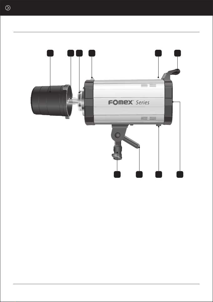
Protection cap
Modeling(Halogen) lamp
Flash tube(Xenon Tube)
Locking knob for accessory assembly
Slave sensor
1.
2.
3.
4.
5.
Lighting grip
Stand stud joint part
Handle for fastening
Wireless control port
Control panel
6.
7.
8.
9.
10.
7
1 2 3 4 5 6
8 9 10
Part Names & Functions of Control panel
2
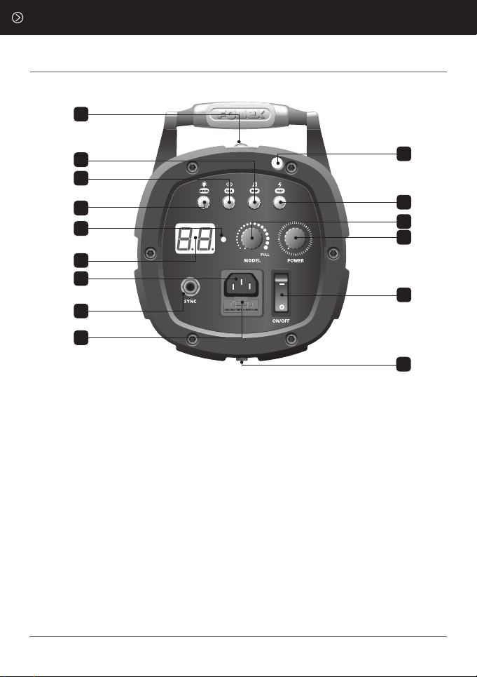
Slave sensor : Synchronize with other
lighting.
BEEP button : Makes a beeping sound
when the flash is charging or discharging.
CELL button : Controls the
synchronization with other lightings.
MODEL button :
E series : ON/OFF
Dp/HDp series : RED, GREED, OFF
O.C Signal : Overcharge signal lamp
turns on when over charged.
FND-Digitally display power output.
O.T Display : Over temperature
warning, display “E0” on the FND
1.
2.
3.
4.
5.
6.
AC input : Socket terminal to connect
the power cord.
SYNC : Socket terminal for synchro cord.
Fuse box : Contains fuse
Umbrella holder
TEST button : To test or to manually
discharge the flash.
Modeling lamp control dial : Controls
the brightness of the modeling lamp.
Flash power control dial : Controls the
power of the flash.
Power switch (ON/OFF)
Wireless control port : Only available
for Fomex's receiver (Option)
7.
8.
9.
10.
11.
12.
13.
14.
15.
3
2
1
3
4
5
6
7
8
9
10
11
12
13
14
15

The settings MODEL / BEEP / CELL buttons are OFF and the modeling & flash
power dials are at a minimum.
Install the modeling lamp to the flash unit.
Be careful not to allow any fingerprint or dust stains on the lamp.
Connect the synchro cord to the synchro socket.
Turn ON the power switch.
Control the power of the flash with the flash power control dial.
Control the brightness of the modeling lamp with the modeling lamp control dial
and press the MODEL button to turn it ON.
To synchronize with other lighting, press the CELL button to turn it ON.
When the power output setting is adjusted from high to low,
the TEST button will flicker.
To turn ON/OFF the flash charging sound, press the BEEP button.
For wired synchronization plug the sync cord into the sync socket and connect it
to the camera. (Use the hot shoes according to the camera model)
For wireless synchronization plug the receiver into the sync socket and connect
the receiver to the camera to check the synchronization status.
(Select a channel based on your wireless synchronizer)
1.
2.
3.
4.
5.
6.
7.
8.
9.
10.
Operating procedure
4
The MODEL button has 3 functions.
- RED LED ON : The brightness of the modeling lamp is adjusted by the modeling lamp
control dial ranged from 0~100%.
- GREEN LED ON : Proportional setting is initiated. The brightness of the modeling
lamp is adjusted by the flash power control dial variable from f2.2 ~f5.63.
- LED OFF : The modeling lamp is off.
Dp/HDp Series Model button control guide

5
Replacement and maintenance
Be sure not to let any dust or other stains on the flash tube
and modeling lamp.
Wipe off any dust or foreign matter on the tube/lamp with a soft cloth.
It may shorten the lifespan and deteriorate the color temperature.
A. How to replace a modeling lamp.
Screw type (Base : E-11)
B. How to replace a fuse.
Turn OFF the power and unplug the power cord from the AC socket.
Turn it counterclockwise and remove the modeling lamp.
Turn the new modeling lamp clockwise to install.
(Please make sure your hands are dry.)
Be careful not to allow any fingerprints, dust or stains on the lamp.
When a foreign substance is present clean with a soft cloth.
Turn OFF the power and unplug the power cord from the AC socket.
Use a (-) screwdriver and open the fuse box to pull out the fuse.
Check if the fuse is blown and replace it with the spare
fuse placed inside the fuse box.
C. Maintenance
1.
2.
3.
4.
Pin type (Base : GX-6.35)
Allow the modeling lamp to cool down enough.
Turn it counterclockwise and remove it.
While assembling, turn it clockwise and then reassemble it.
Be careful not to allow any fingerprints, dust or stains on the lamp.
Clean it with a soft cloth applied with alcohol after replacement.
1.
2.
3.
4.
1.
2.
3.
6
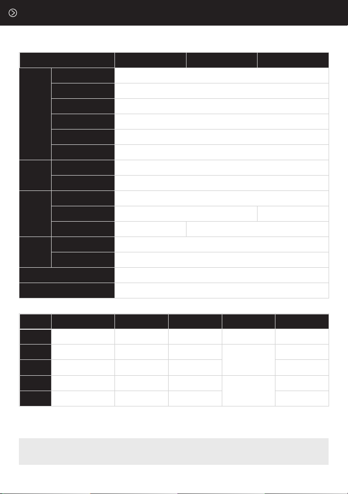
Technical Specifications
The listed values may differ due to tolerances in components and measuring instruments.
Technical data is subjected to change without prior notice.
E series Dp series HDp series
Power Control
Power Range Display
Color Temperature
Over Charge Warning
Flash Ready Indicator
AC Input Voltage
Fuse Capacity
Type
Wattage
Control Modes
Sync Type
Sync Voltage
Over Temperature
Warning
Cooling System
Buttons
POWER
Sync
Modeling
Light
Flash Head
Maximum Power F-Stop(1m, ISO100) Recycle Time Dimension mm
(W x L x H) Weight
4.0 ~ 10 Digital
5,500K (±150K)
6steps in 1/10 f-stops
AC 220V 50/60Hz (AC 110V Option)
10A
LED Light / Buzzer (Sound ON)
Display (E0) on the FND / Warning Buzzer
Red LED Light
Tungsten
Cable, Optical, Radio(Option)
Halogen 650W
(GX 6.35 base)
Halogen 250W (E 11base, Screw type)
Volumecontroller,
Model(ON/OFF)
Proportional, Volumecontroller,
Model(ON/OFF)
Model, Cell, Beep, Test ON/OFF
DC Cooling Fan
DC 8V
200 200Ws
400 400Ws
600 600Ws
800 800Ws
1000 1000Ws
F22.6
(6f-stops)
F32.7
(6f-stops)
F45.5
(6f-stops)
F64.0
(6f-stops)
F64.2
(6f-stops)
0.1~0.7sec
0.1~1.0sec
0.1~1.3sec
0.2~1.3sec
0.3~1.7sec
296x140x220mm
370x140x220mm
430x140x220mm
2.3kg/5lbs
2.8kg/6.1lbs
3.0kg/6.6lbs
3.4kg/7.5lbs
3.6kg/8lbs
Check the input voltage.
When the input voltage is lower than the rated voltage, the flash may not produce its
maximum output.
Disconnect this unit from the power supply before changing a bulb or a fuse.
Use the specified fuse only.
Do not use in humid or hazardous places or near inflammable materials.
The flash can stop working to enable cooling after maximum output and long-term
continuous use.
Do not use the flash near the eyes.
For safety, please power OFF when not in use.
Do not move the flash while the power is on.
Make sure not to use a softbox near inflammable materials.
The heat emitted from the product may cause a fire.
Do not drop and shock the product.
When either assembling or disassembling accessories (e.g.snoot, reflector, etc.),
turn OFF the modeling lamp and wait for at least 10 minutes before changing
and replacing the accessories.
Never open this unit, high voltage inside.
No internal serviceable parts.
The separation distance of the product is 0.5m at least.
Fomex accepts no responsibility for electric shock or equipment damage
due to unauthorized modification and repairs.
Keep out of children’s reach.
Notice
7
1.
2.
3.
4.
5.
6.
7.
8.
9.
10.
11.
12.
13.
14.
15.
16.
electric shock(symbol) 0.5m over(symbol)

8
Halogen lamps safety measures
Avoid contact with bare hands and wear dry cloth or gloves when handling.
When moving the strobe turn off the power and treat it safely.
Make sure that the residual heat of the lamp is sufficiently cooled before handling.
When the lamp is overheated the lack of attention to the above precautions may lead to the
risk of explosion. Be sure to use a protective device (Pyrex dome, Softbox) while in use.
Please keep a proper distance between the subject and the lamp when taking portraits, and
do not use it without a protective device.
Troubleshooting
Status
The slave is not
working.
The synchro cord
doesn’t work.
There’s no
reaction at all.
Expected cause
The CELL button is turned OFF.
The flash light doesn’t reach
the slave sensor.
A strong external light is directed
at the slave sensor.
Foreign material presents on the
synchro jack, it causes a contact
defect.
The synchro cord is disconnected or
failed to function after cleaning.
The Power Supply is interrupted
Check if the power cord is properly
connected.
Check if the contact of the socket
is loose.
Check if the fuse is blown.
Other trouble
shoots Please contact your local dealer or contact FOMEX directly.
Checkpoints
Check whether the CELL button
is turned ON.
Change the directionality of the
lighting unit.
Check if it’s still not working.
Check the synchro jack for any
presence of foreign materials, and
clean it with a soft cloth.
Replace the synchro cord.
(Press the TEST button to check)
Block direct ray of light or strong
light from the slave sensor.
1.
2.
3.
4.
5.
Inapplicable Warranty
The following cases are excluded from the warranty terms specified above.
1. Expired warranty period
2. Breakage or damage caused by inappropriate usage, repair, maintenance and accident.
1) Installation and removal with improper external equipment or improper usage.
2) Damage to the product caused by external fault or any accident.
3) Exposure to extreme environment such as abnormal temperature,
solvents, acids, bases, floods, humidity.
4) External damage like scratches, crushes or cracks.
5) If the serial number is defected or cannot be identified.
3. Damage caused by installation, repair, improvement, addition, disassembly
by unauthorized institution or person.
4. Modified, replaced, removed information identifying the original product
5. Absence of valid warranty card
6. Unusable or damage caused by the use of illegal nonstandard and unofficial software
7. Damage caused by accident, abuse, misuse, floods, fires, earthquakes or other external causes.
8. Supplies such as flash tubes, lamps, charger capacitors, etc.
Fomex’s warranty provisions of the product are listed as below.
When a defect occurs within the warranty period, it will be repaired with new or refurbished
parts for free.
Or, it will be replaced with a new product or a functionally equivalent refurbished product.
This warranty applies only to products manufactured by Fomex that can be identified by the
trademark, trade name, or logo affixed to the product.
Customer Information
Seller Information
Product
Name
Contact Number
Address
Name
Contact Number
Address
Purchasing date
Name
Please keep the confirmation of purchase and this warranty card for future service.
Warranty
9

www.fomex.com
7th Floor, Seongsui-ro, Seongdong-gu, Seoul Korea 04787
Tel: +82 2 545 0004 Fax: +82 2 3444 9399 E-mail: info@fomex.com
VER.202107(EN)
This manual suits for next models
2
Table of contents
Other fomex Lighting Equipment manuals


Popular Lighting Equipment manuals by other brands


Lightolier
Lightolier Lighting Systems F7000-16 Specification sheet

NSi INDUSTRIES
NSi INDUSTRIES Tork 2100 Series Mounting and installation

Zodiac
Zodiac pH Link Instructions for installation and use

ADJ
ADJ H2O LED User instructions

thomann
thomann Varytec Hero Wash 300 TW user manual

EuroLite
EuroLite LED PAR-56 QCL Short user manual

Motorisation+
Motorisation+ LUMI24 Instructions and warnings for installation and use

HEPER
HEPER LW6048.575-EN Installation & maintenance instructions

Hyundai
Hyundai HSL121903 user manual

Rave Sports
Rave Sports Turbo Chute owner's manual

Ltech
Ltech LT-701-CC manual

Ansult
Ansult 005579 operating instructions