Dr. Mach LED 150F Manual

Mach LED 150F / 150 / 150FP
59320002 Edition 12 08.08.2018 / Bak We page 2/26
List of contents
1. Safety instructions.................................................................................... page 4
2. Brief description of the light MACH LED 150F / 150 / 150FP................... page 8
3. Operating the light Mach LED 150F / 150 / 150FP...................................page 8
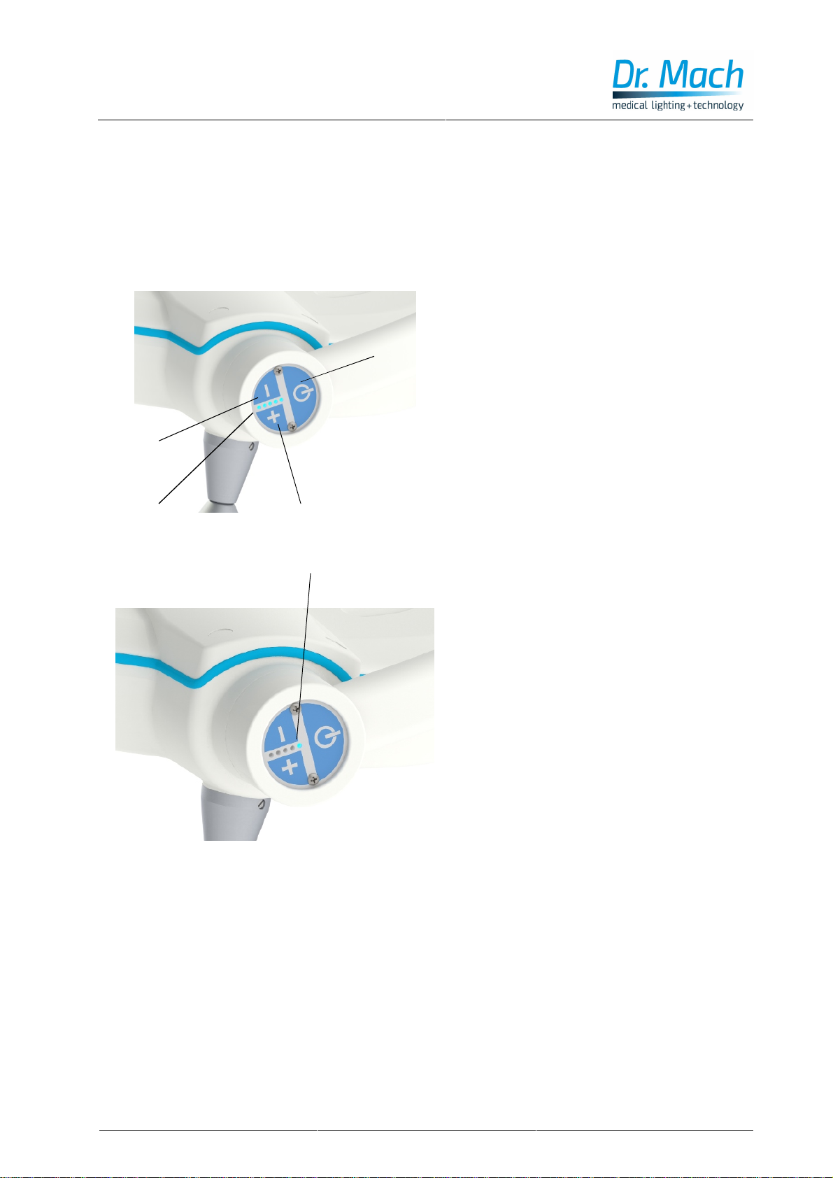
3.1 ON/OFF switch .................................................................................. page 8
3.2 Light intensity control......................................................................... page 8
3.3 Endo –Light (Mach LED 150 / 150F/150FP 4500 Kelvin only).......... page 8
3.3 Focusing (Mach LED 150F / 150FP only).......................................... page 9
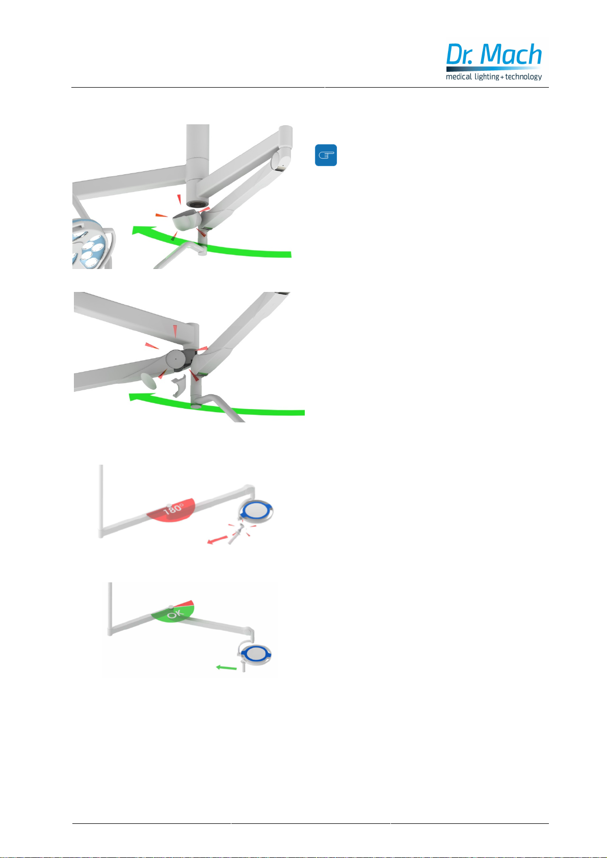
3.4 Positioning ......................................................................................... page 9
3.5 Danger of collision while positioning the lights...................................page 10
3.6 Addition to positioning the lamp......................................................... page 10
4. Cleaning................................................................................................... page 11
4.1 Sterilisable handle..............................................................................page 11
4.2 Lamp head, lens and protective disk.................................................. page 13
5. Initial operation and Maintenance ............................................................ page 14
5.1 Activity at initial operation and maintenance work.............................. page 14
6. Troubleshooting .......................................................................................page 15
7. Data ......................................................................................................... page 16
7.1 Technical data.................................................................................... page 16
7.2 Electrical data .................................................................................... page 17
7.3 Information regarding the electrical installation.................................. page 17
7.4 Weights.............................................................................................. page 17
7.5 Environmental conditions...................................................................page 18
7.6 General remarks................................................................................ page 19
8. CE-mark................................................................................................... page 19
9. Disposal ................................................................................................... page 19
10. Wiring diagram.......................................................................................page 20
11. Electromagnetic compatibility.................................................................page 21

Mach LED 150F / 150 / 150FP
59320002 Edition 12 08.08.2018 / Bak We page 3/26
Dear customer!
Congratulations for acquiring our new light MACH LED 150F / LED 150 / LED 150FP.
The new light generation with LED technology supports your professionalism by innovative technology
and design.
The advantages of the LED technology: a life-span of minimum 50.000 hours and an almost non-
existent heat development in the surgeon’s head area and in the wound field.
The advantages already provided by Dr. Mach’s light technology with halogen and gas discharge
lamps have been maintained: natural colour reproduction, exact illumination of the wound field and
easy positioning of the light head.
All information quoted here relates only to the illuminant. Details of ceiling or wall installation can be found
in the mounting instructions.

Mach LED 150F / 150 / 150FP
59320002 Edition 12 08.08.2018 / Bak We page 4/26
1.
Safety instructions
Pay attention to the instructions for use when handling the lamp.
WARNING:
This device has not been designed for use in potentially explosive areas.
According to the Medical Device Regulation the light is classified under class I.
Store the light in its package for at least 24 hours in the respective room before mounting, in order
to equal temperature differences.
Please read the instructions for use carefully to make the most of your lighting system and to avoid
any damages to the device.
The lights may only be repaired and special assembly work may only be carried out on the reflec-
tor or sockets by Dr. Mach or a company that has been expressly authorized by Dr. Mach.
The manufacturer can only be made responsible for the safety of the light if repairs and alterations
are carried out by the manufacturer himself or a company that guarantees to observe the safety
regulations.
No modification of the lamp is allowed!
The manufacturer cannot be made liable for personal or material damages if the light is operated
inexpediently or incorrectly or used for purposes other than those for which it is intended.
The light is to be dismantled from the spring arm in reverse order to its assembly. This may only
be carried out after the spring arm has been adjusted in height at horizontal position since the
arm is under spring tension and can bounce up.
Make sure that the light is in perfect working order before every use.
Attention, external power supply!
The light works only with an external power supply 60VA.
The external power supply used with the light must be tested and validated according to IEC
60601-1.
Attention!
A main control switch must be installed for turning the system power-off. The switch must meet
the requirements of the standard IEC 61058-1 regarding rated voltage peaks of 4kV.
During the mounting of the lights the entire system (incl. the ceiling attachment) must be disconnect-
ed from mains!
A later dismounting of the lights from the spring arms or dismounting the sliding contacts inside the
arms is to be done ONLY AFTER DISCONNECTING THE ENTIRE SYSTEM FROM MAINS.
Otherwise the electronic board will be damaged!

Mach LED 150F / 150 / 150FP
59320002 Edition 12 08.08.2018 / Bak We page 5/26
Symbols and notes used in this user manual:
This symbol means possible hazard sources. Please observe also the safety remarks and
the hazard specifications mentioned in the mounting instructions and user manuals from
Ondal company.
This symbol means possible hazard caused by electric current. Please observe also the
safety remarks and the hazard specifications mentioned in the mounting instructions and
user manuals from Ondal company.
This symbol refers to important mounting indications, useful information and operation hints.
Temperature range for transport and storage
Indication for disposal
CE- conformity mark
This way up
Keep dry
Fragile, Handle with care

Mach LED 150F / 150 / 150FP
59320002 Edition 12 08.08.2018 / Bak We page 6/26
Symbols and notes used on the device:
This symbol indicates to observe the user manual.
Indication on China RoHS / Pollution control Logo China
Temperature range for transport and storage
Indication for disposal
Serial number of the product
Article number of the product
Address of manufacturer / distributor of the product
Year of manufacture
CE- conformity mark
Quality control
This symbol indicates the certification mark of the TÜV.

Mach LED 150F / 150 / 150FP
59320002 Edition 12 08.08.2018 / Bak We page 7/26
2.
Brief description of the light MACH LED 150F / 150 / 150FP
Mach LED 150F/150/150FP intended use:
The Mach LED 150F/150 lighting system is designed for illuminating an examination area at the hospital
and doctor’s practice.
Mach LED 150F/150/150FP indications for use:
The surgical light MACH LED 150F/150/150FP is intended to illuminate the surgical field and the patient’s
body with a high intensity, shadow-free and “cold”light.
Essential Performance:
The surgical light Mach LED 150F/150/150FP is intended to illuminate in depth and to restrict the energy
on the operating field.
General product description:
•The Mach LED 150F/150/150FP lighting system is an examination light according to EN 60601-2-
41, which is not fail-safe when used as a single light.
•The Mach LED 150F/150/150FP lighting system is designed to support therapy and diagnosis.
•The light is used in medical rooms (groups 0, 1 and 2 according to DIN VDE 0100-710 respec-
tively HD 60364-7-710).
•This light system can be added to the ceiling mounted suspension system supporting the
horizontal arms and spring arms, as well as a wall light or mobile light.
•The maintenance of the light must take place every two years.
•The electrical connection for the ceiling and wall lights is done by a fixed connection.
The examination light Mach LED 150F/150/150FP is available in following versions:
-
Mach LED 150F with light intensity control and focusing function.
-
Mach LED 150 with light intensity control and fixed-focus.
-
Mach LED 150F with light intensity control, focusing function and sterilizable handle.
-
Mach LED 150 with light intensity control, fixed-focus and sterilizable handle.
-
Mach LED 150FP with light intensity control and focusing function.
-
Mac LED 150FP with light intensity control, focusing function and sterilizable handle.
Accessory
The accessories for the Mach LED 150F/150/150FP lighting systems are as follows:
Camera module
Remote control for camera module
Single monitor yoke for flat panel monitors
Double monitor yoke for flat panel monitors
Instrument trays
24V DC battery backup support
Sterile handle sleeves

Mach LED 150F / 150 / 150FP
59320002 Edition 12 08.08.2018 / Bak We page 8/26
3.
Operating the light MACH LED 150F / 150 / 150FP
3.1
ON/OFF switch
The push button 1on the control panel turns
the light MACH LED 150F/150/150 FP ON and
OFF.
3.2
Light intensity control
The lights Mach LED 150F/150/150 FP offer the
facility of light intensity control.
The adjustment range of the light intensity is
from 50 % to 100 %.
The light intensity can be adjusted according to
the requirements of the surgeon / physician.
The light intensity can be decreased by
pressing push button 2.
The light intensity can be increased by pressing
push button 3.
The set light intensity is shown by the display 4.
3.3 Endo – Light (Mach LED
150/150F/150FP with 4500 Kelvin)
In case of endoscopic intervention the light of
the OT- lamp with 4500 Kelvin (optional) can be
dimmed.
The Endo mode is activated by repeated press-
ing of the – key, until only LED 4is on. When
pressing the – key again, LED 4goes off and
LED 5turns on automatically.
The Endo mode is now active.
This mode can be deactivated by pressing the +
key.
1
2
3
4
5

Mach LED 150F / 150 / 150FP
59320002 Edition 12 08.08.2018 / Bak We page 9/26
3.4 Focusing
The lamp-models Mach LED 150F/150FP have a
focusing function. That means, you can either en-
large the diameter of the light field or bundle the light
to a smaller area, depending on the circumstances.
To activate the function of focusing turn the handle 5
(see figure).
3.5 Positioning
Use the handle 5or the handle rail 6to position the
lamp.
Use the handle rail to position the lights before the
operation.
Use the handle for positioning the light during the
operation.
Remark:
Position the light only with the handle or the
special designed parts on the light housing
5
6
5

Mach LED 150F / 150 / 150FP
59320002 Edition 12 08.08.2018 / Bak We page 10/26
3.6 Danger of collision while positioning
the lights
During positioning, eventual collisions between
the lights, spring arms and other devices must be
avoided.
Cover parts can get loose and fall down.
3.7 Addition to positioning the lamp
When the spring arm and extension arm are in a
180° position, the lamp head cannot be moved in the
direction of the suspension axis.
A repeated force of > 25 N (according to EN 60601-
2-41) at this angle can lead to damage.
This applies for all ceiling and wall mounted lamps
(example in picture).
In order to be able to move the lamp in the direction
of its suspension axis, the angle between the exten-
sion arm and spring arm must be < 180°.

Mach LED 150F / 150 / 150FP
59320002 Edition 12 08.08.2018 / Bak We page 11/26
4.
Cleaning
4.1 Sterilizable handle
The light can be equipped against surcharge with
the sterilisable handle 7. The handle sleeve is
removable and sterilisable. Before using the first
time and before every use the handle sleeve must
be cleaned, disinfected and sterilised.
The handle sleeve must be removed for sterilisation:
•To remove press the lock Vand pull off the steri-
lisable handle sleeve 7while keeping the lock
pressed.
•To attach, push on and slightly twist the handle
until the lock Vengages securely.
Handles often become unsterile during an
operation. Therefore always keep additional handles
available for exchange.
Cleaning / disinfection and sterilisation
Basics
Efficient cleaning / disinfection is an essential requirement for effective sterilisation of the handle.
Within the scope of responsibility for the sterility of the products it should be noted that only sufficiently
validated equipment and product specific processes are used for cleaning / disinfection and that the
validated parameters are complied with in every cycle.
In addition, the hospital / clinic hygiene regulations must be observed.
Remark:
The requirements of the national committees (standards and directives) for hygienics and disin-
fection must be observed.
Cleaning / disinfection
Cleaning and disinfection must be carried out immediately after use.
A mechanised process(disinfector) should be used for cleaning / disinfection. The efficiency of the
process used must be recognised and validated in principle (e.g. listed under disinfectants and
disinfection procedures tested and recognised by Robert-Koch-Institute / DGHM).
When using other procedures (e.g. a manual procedure), proof and process efficiency in principle must
be provided within the scope of validation.
Proof in principle of the suitability of the handles for efficient cleaning / disinfection was provided using a
cyclic cleaning system (Netsch-Bellmed T-600-IUDT/AN, programme 2 for small parts; code B).
It is not allowed to use agents / disinfectants, which contain the following substances, as these may
cause changes in the material:
-
High-concentration organic and inorganic acids
-
Chlorinated hydrocarbons
-
2-ethoxyethanol
7 V

Mach LED 150F / 150 / 150FP
59320002 Edition 12 08.08.2018 / Bak We page 12/26
When cleaning / disinfecting, the following procedures must be followed:
Process Time (sec.)
Zone 1 Pre-rinse, external, cold, 10 –15°C 45
Washing, acidic, external 35°C 120
Draining time 10
Re-rinse, external approx. 80°C *10
Draining time *15
Re-rinse, external approx. 80°C *15
Draining time 15
Zone 2 Washing, alkaline, external, 93°C 135
Draining time 10
Re-rinse, external, acidic, 90°C 10
Draining time 15
Re-rinse, external 90°C 15
Draining time 15
Zone 3 Drying, external 100 –120°C 200
Zone 4 Drying, external 100 –120°C 200
Door open / close & transport 60
(sluice discharge)
Cycle time overall ca. 890
≈15 minutes
* When occupying the disinfection zone (washing zone 2), the re-rinse and draining times will depend on
the respective objects being washed therein!
Sterilisation
Only previously cleaned and disinfected handles may be sterilised.
The handles are placed in a suitable sterilisation pack (one-way sterilisation pack, e.g. foil / paper sterili-
sation bags, single or double pack) in accordance with DIN EN 868 / ISO 11607 for steam sterilisation
and then sterilised.
Use only the sterilisation procedure listed below for sterilisation. Other sterilisation procedures (e.g.
ethylene oxide, formaldehyde and low-temperature plasma sterilisation) are not permissible.
Steam sterilisation procedure
Validated in accordance with DIN EN 554/ISO 11134
Maximum sterilisation temperature 134°C
Proof in principle of the handles’suitability for effective sterilisation was provided using a fractional vacu-
um process (Euroselectomat 666 by MMM Münchner Medizin Mechanik GmbH, sterilising temperature
134°C, holding time 7 min.).
When applying other sterilization procedures, the suitability and effectiveness of the process must be
validated.

Mach LED 150F / 150 / 150FP
59320002 Edition 12 08.08.2018 / Bak We page 13/26
Inspection / durability
The sterilisable handle sleeve must be disposed
after 1000 sterilisation cycles or at the latest after
2 years and replaced with a new one.
The year of manufacture can be determined with
the help of a stamping on the inner side of the
handle sleeve (like shown in the photo). The
stamping in the photo shows the number 12,
which stands for the year 2012.
4.2 Lamp housing, protective disk
and support system
The Dr. Mach light system has a high-quality
surface, which can be cleaned with conventional
cleaning agents.
The protective disk 8 is made of a high-quality
plastic. Pay attention to the following during
cleaning:
-
Never wipe over the protective disk 8 with a dry
cloth (always clean with a wet cloth).
-
Wipe the protective disk 8after cleaning with an
antistatic, non-fluffy cloth.
8

Mach LED 150F / 150 / 150FP
59320002 Edition 12 08.08.2018 / Bak We page 14/26
5.
Initial operation and Maintenance
Preventive maintenance of the light must take place every two years. This includes a technical and
mechanical check-up.
Please observe also the mounting instructions and instructions for the carrying systems. These
instructions can contain statements for different maintenance intervals.
Basis of the examination of the lighting and load-bearing systems forms the DGV V3 (formerly BGV-A3)
in connection with the EN 62353.
Attention:
Set the height adjustment, if applicable, of the spring arm to horizontal position before dismount-
ing the lamp. Please observe also the mounting instructions and instructions for the carrying
systems.
Attention: During all maintenance work the light must be disconnected from mains and
secured against resetting.
5.1 Activity at initial operation and maintenance work
The following maintenance work / tests has / have to be done:
•check on defects in paint work;
•check on fissures at plastic parts;
•check on deformation of the suspension.
•check on loosened parts;
•check the connection between light and carrying system;
•check and grease the securing segment;
•check the faultless function of the light;
•perform the electrical safety tests
For adjustments at the ceiling attachment please observe also the mounting instructions “Ceiling
attachment with heavy central axis”or “Ceiling attachment –wall attachment”from Dr. Mach.
Remark:
Wiring diagrams, complete spare parts lists and maintenance manuals can be provided on
request.
It is not allowed to exchange spare parts and make repair work while the light is in operation.
It is not allowed to touch parts below the housing cover and to touch the patient at the same time.

Mach LED 150F / 150 / 150FP
59320002 Edition 12 08.08.2018 / Bak We page 15/26
6. Troubleshooting
LED 150 in combination with the spring arm Acrobat 2000
1. The light cannot be switched on after the installation:
2. The spring arm cannot be adjusted as required:
Remark for adjusting the spring force
Please make sure, that the adjusting screw in the spring arm (see pictures below) is turned so far, until a
resistance is noticeable! An overturn of the screwdamages the spring arm irreversible!
Pull off the plastic
cap at the rear joint
of the spring arm.
View of the joint
without plastic cap.
The adjusting screw
is positioned at the
top.
Adjust the spring force
with this screw accord-
ing to the mounting in-
structions.
a.) Is the light connected to mains?
→
Mobile light:
Plug the mains plug into the wall socket.
→Wall light or ceiling light:
The power supply of the light must be connected to
the electric circuit according to the included wiring
diagram. You can check the correct connection by
measuring the voltage at the primary side of the
power supply.
b.) Is the securing segment installed be-
tween the light and the spring arm?
→
Check if the securing segment is installed. In case
the securing segment is not installed, install it ac-
cording to the mounting instructions. (The securing
segment is part of the accessories of the spring
arm.)
c.) The light is connected to mains (a.) and
the securing segment is installed cor-
rectly (b.), but the light cannot be
switched on.
→
Disconnect the light from the mains power supply
for a short time:
Mobile light:
Unplug the mains plug from the wall socket.
Wall light or ceiling light:
Turn off the light on the wall switch or disconnect it
from the electric circuit by pulling the mains fuse.
Reconnect the light to mains and switch on the
light.
a.) The light head is not yet mounted to the
spring arm.
→
Install the light to the spring arm according to the moun
t-
ing instructions. After that the spring arm can be moved
easier.
b.) The light head does not hold its position
and moves upwards
and moves downwards
→
Adjust the spring force of the spring arm according to
the mounting instructions. Please observe the below
remark for adjusting the spring force.

Mach LED 150F / 150 / 150FP
59320002 Edition 12 08.08.2018 / Bak We page 16/26
7.
Data
ED Mach M3 LED
7.1 Technical data
Mach LED 150F Mach LED 150 Mach LED 150FP
Central light intensity
at a distance of 1 meter 110.000 Lux 110.000 Lux 130.000 Lux
Light field diameter d10 187 mm 200 mm 172 mm
Light field diameter d50 96 mm 113 mm 90 mm
Light intensity with one shadower 0 % 0 % 0 %
Light intensity with two shadowers 55 % 50 % 54 %
Light intensity on the ground of a
normed tube 100 % 100 % 100 %
Light intensity on the ground of a
normed tube with one shadower 0 % 0 % 0 %
Light intensity on the ground of a
normed tube with two shadowers 55 % 50 % 54 %
Illumination depth 20% 1800 mm 1780 mm 1800 mm
Illumination depth 60% 900 mm 800 mm 840 mm
Colour rendering index Ra96 96 96
Colour rendering index R994 94 94
Max. radiation in field
in a distance of 1 meter 379 W/m² 376 W/m² 459 W/m2
Max. radiation in field
in a distance of 0,85 meters 454 W/m² 460 W/m² 541 W/m²
Focusable
light field size 18-25 cm 19 cm (fixed focus) 17-24 cm
Colour temperature (Kelvin) 4300 K* 4300 K* 4300 K*
Electronic light intensity control
at the light head (standard) 50-100 % 50-100 % 50-100 %
Temperature increase
in head area 0,5 °C 0,5 °C 0,5 °C
Number of LED’s 26 26 26
Life span of LED’s 50.000 h 50.000 h 50.000 h
Working distance 70-140 cm 70-140 cm 70-140 cm
Diameter of the light head 40 cm 40 cm 40 cm
Height adjustment 118 cm 118 cm 118 cm
*Surcharge for a colour temperature of 4500 Kelvin.
Remark:
The technical data are subject to fluctuations. Due to manufacturing reasons the real values can slightly differ from the
data mentioned above.
The values for R
a
and R
9
can differ with approx ± 5%.
The values for the colour temperature can differ with approx ± 200K.

Mach LED 150F / 150 / 150FP
59320002 Edition 12 08.08.2018 / Bak We page 17/26
7.2 Electrical data
Mach LED 150F Mach LED 150 Mach LED 150FP
Power consumption 35 W 35 W 35 W
Operating voltage DC 24 V DC 24 V DC 24 V DC
Current 1,45 A 1,45 A 1,45 A
7.3 Information regarding the electrical installation
When turned ON, the examination light MACH LED 150F / 150 / 150FP is exposed to a current peak.
The examination light MACH LED 150F / 150 /150FP is delivered with a Dr. Mach power supply.
It is an electronic power supply with a wide-range input, input voltage 100 –240V AC, 50 –60Hz, output
voltage 24V DC.
In case there is a switch-over relay needed for a emergency power supply on site, this switch over relay
must be ordered separately at Dr. Mach.
In case of a power supply provided by the customer, the following points must be observed:
•The OT-light works with 24V DC (direct voltage).
•The direct voltage provided by the hospital must have a maximum undulation of 5%.
Warning!
The light is class I. equipment. In order to avoid the risk of an electric shock, the equipment must
be connected to a mains supply with protective earth.
7.4
Weights
Light Weight
Mach LED 150F 3,5 kg*
Mach LED 150 3,5 kg*
Mach LED 150FP 3,5 kg*
* without handle

Mach LED 150F / 150 / 150FP
59320002 Edition 12 08.08.2018 / Bak We page 18/26
7.5 Environmental conditions
Operation
Min. Max.
Temperature +10°C +30°C*
Relative atmospheric humidity 30 % 75 %
Air pressure 700 hPa 1060 hPa
* in case of higher temperatures please contact us
Transport / storage
Min. Max.
Temperature -10°C +50°C
Relative atmospheric humidity 20 % 90 %
Air pressure 700 hPa 1060 hPa
References on the package
This way up Keep dry Fragile, Handle with care
Temperature range
for transport
and storage
Atmospheric
humidity
for transport
and storage
Air pressure
for transport
and storage

Mach LED 150F / 150 / 150FP
59320002 Edition 12 08.08.2018 / Bak We page 19/26
7.6 General remarks
When using more than one light at the same time (light combinations), due to the overlapping of
the light fields of different lights, the total radiation intensity can exceed the value of 1000 W/m
2
. This
means a risk of higher heat development in the wound field.
When using more than one light at the same time (light combinations), due to the light fields overlapping
of different lights the maximum permissible values for UV-radiation (< 400 nm) of 10 W/m² can be ex-
ceeded.
The test certificate for the electrical safety test can be requested when needed. Please
provide the serial number of the respective light.
In case of a collective wiring of further lights or devices at installation, chapter 16 of the European
standard EN 60601-1:2013 must be applied and eventually it has to be checked if the requirements
are met.
The light must be tested according to EN 62353 at commissioning.
The polarity is very important for the installation of the light. In case the light does not
function after installation, the polarity must be checked at the secondary side of the power sup-
ply.
8.
CE-mark
The products Mach LED 150F / 150 / 150FP comply with the standards 93/42/EEC for
medical products of the European Community’s Council.
Dr. Mach applies the standard EN 60601-2-41.
Dr. Mach GmbH is certified according to EN ISO 13485:2012 + AC:2012.
9.
Disposal
The light doesn’t contain any dangerous goods.
The components of the light should be properly disposed at the end of its shelf-life.
Make sure, that the materials are carefully separated.
The electrical conducting boards should be submitted to an appropriate recycling
proceeding.
The rest of the components should be disposed according to the contained materials.

Mach LED 150F / 150 / 150FP
59320002 Edition 12 08.08.2018 / Bak We page 20/26
10.
Wiring diagram for single attachments
power supply type: XP Power ECM60US24
This manual suits for next models
2
Table of contents
Other Dr. Mach Lighting Equipment manuals