Fontaine 3000 series User manual

FIFTH WHEEL
2” Cast Fifth Wheel
2” Guss-Sattelkupplung
Sellette 2” en fonte
Instruction anual
ontage- und Betriebsanleitung
Notice d’utilisation
®
C O N N E C T Y O U R B U S I N E S S W I T H F O N T a I N E

Safety Information ........................................................................................ 2
1.1 Operation ............................................................................................ 2
1.2 Installation ............................................................................................ 2
1.3 Servicing .............................................................................................. 2
Correct Usage ................................................................................................ 3
2.1 Application .......................................................................................... 3
2.2 Design .................................................................................................... 3
2.3 Warranty ................................................................................................ 4
Operation ............................................................................................................ 5
3.1 Connecting a semi-trailer ............................................................ 5
3.2 Checking the fifth wheel is properly connected .............. 5
3.3 Disconnecting the semi-trailer .................................................... 7
Servicing and Testing ................................................................................ 8
4.1 Servicing .............................................................................................. 8
4.2 Lubrication ........................................................................................ 10
4.3 Spare Parts ........................................................................................ 11
Installation ........................................................................................................ 12
5.1 Choice of fifth wheel .................................................................... 12
5.2 Mounting bolts ................................................................................ 12
5.3 Mounting of fifth wheel coupling to mounting frame ....13
5.4 Mounting of plates, dolly mounting plates, frames
and sliding fifth wheels ................................................................ 13
5.5 Bolt positions .................................................................................... 14
5.6 Positioning of equipment on vehicle .................................. 14
3000 Fifth Wheel Instruction anual
1
C O T E T S
English

It is important to remember that a fifth wheel is a safety critical item
and should be treated as such.
Proper preventative maintenance, inspection and lubrication are
essential for a long, safe and trouble-free service life.
Please observe the relevant safety regulations that apply for
working with fifth wheel couplings, tractor units and semi-trailers.
These regulations will vary in different countries.
1.1 Operation
• Only authorised users are permitted to use the fifth wheel
coupling.
• Do not use the fifth wheel coupling and rubbing plates if
they show any sign of technical problems.
• The rubbing plate must be larger than the support area
of the fifth wheel coupling.
• Any sharp edges must be removed from rubbing plate to
prevent damage to the fifth wheel coupling or the top
plate liner, if fitted.
• When connecting a semi-trailer ensure all safety
regulations are adhered to. e.g. Health and Safety at Work
Regulations. A semi-trailer should only be connected on
firm, flat ground.
• The rubbing plate should ideally be slightly lower than the
top plate but not by more than 50mm.
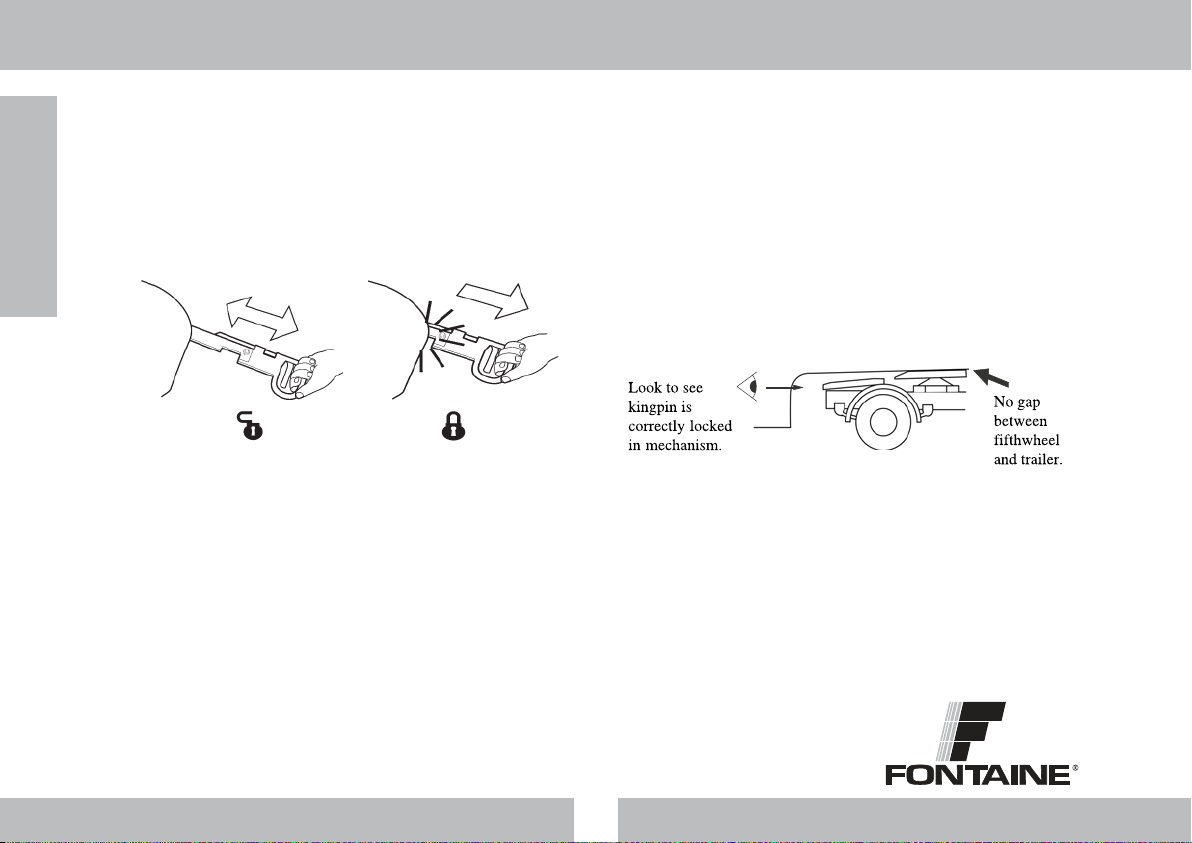
• Ensure the locking mechanism is properly locked before
starting every journey. The vehicle must only be driven
when the mechanism is locked and secured, even when
driving without a semi-trailer.
1.2 Installation
• Prior to installation of a fifth wheel on a vehicle the
following should be considered:-
✱Current Legislation
✱OEM Vehicle Installation Instructions
✱Fontaine Vehicle Specific Mounting Instructions
• Installation work must only be completed by authorised
specialists.
• Installation areas are defined by the tractor unit
manufacturer and must not be changed.
• In all cases fifth wheel equipment should be mounted
using the mounting holes positioned as supplied.
The fifth wheel coupling must be mounted on the vehicle in
compliance with the requirements of Appendix VII of
Directive 94/20/EC. It may also be necessary to comply with
the licensing regulations of the appropriate country.
1.3 Servicing
• Only use specified lubricants for the servicing work
• The servicing work should only be completed by trained
personnel.
• Only use Original Equipment parts.
3000 Fifth Wheel Instruction anual
2
S A F E T Y I F O R M A T I O
English

2.1 Application
Fifth wheel couplings connect the tractor unit and the semi-trailer.
They are designed to be mounted on the tractor unit and should
be done so in a way that complies with Fontaine International’s
mounting instructions.
The fifth wheel coupling and mounting plates are connecting parts
that must meet very high safety standards and design approval
tests.
Any kind of modification to either the fifth wheel or auxiliary
mounting equipment will void the warranty and design approval.
2.2 Design
All Fontaine International fifth wheel couplings are designed to
comply with Directive 94/20/EC Class G50 and are to be used
together with king pins of Class H50 and Class mounting plates
or with comparable licensed equipment. This standard rates fifth
wheel coupling equipment based on the Maximum Imposed
(vertical) load and the Drawbar value, more commonly known as
the ‘D’ value. If any doubts exist as to which is the correct Fifth wheel
Equipment to use then the correct rating can be checked by
calculation using the formula in Figure 1.
Calculating D value where:-
g = 9.81 m/s2
R = Maximum gross weight of the semi-trailer [kg]
T = Maximum gross weight [kg]
U = Maximum imposed load [kg]
The maximum load data can be found on the fifth wheel type
label (see figure 2) and on the Fontaine technical documents. Also
the Fontaine website has a D-value calculator under the “selecting
the right product” section.
The Fifth wheel Coupling chosen should be rated with loads equal
to or higher than the calculated values. Under no circumstances
should a coupling be fitted where the calculated rating is higher
than the values indicated on the equipment type plate.
Allowances to the D-value and Maximum imposed load should be
made if the coupling is subject to additional dynamic forces, for
example if they are used on uneven road surfaces or on
construction sites such as quarry or forestry work. For this type of
application a higher rated fifth wheel may be required. If in any
doubt contact Fontaine technical department.
3000 Fifth Wheel Instruction anual
3
C O R R E C T U S A G E
English
Figure 1
Figure 2 - Fifth wheel Type Label
D = 9,81 x 0,6 x T x R
T +R - U
T (kg) R (kg)
U (kg)

2.3 Warranty
Fontaine International Europe Ltd warrants that all fifth wheels
produced by the company to be free from defects in material and
workmanship - excluding mounting components not supplied as
an original part of the fifth wheel assembly.
The Warranty Period for Fontaine Products is:-
• 2 Years Parts and Labour
All Installations must be carried out to within the company’s Fifth
wheel Mounting Instructions.
These Warranty Terms cover failures in material and workmanship
but does not cover failures due to the following:-
a. Vehicles which are not used on normal Highway
conditions
b. Accident
c. Improper Installation (refer to Fontaine official mounting
instructions)
d. General wear and tear
e. Misuse alteration or neglect
f. Failure to properly maintain (refer to Fontaine Official
maintenance instructions) using company’s genuine
parts.
The company must be notified prior to the commencement of any
repair. Failure to do this will cause automatic rejection of the claim.
3000 Fifth Wheel Instruction anual
4
C O R R E C T U S A G E
English

3.1 Connecting a semi-trailer
1. Check that the trailer hand brake is set and check that the fifth
wheel is open and ready for coupling (see Figure 3). If there is
any doubt, carry out the uncoupling procedure (section 3.3) until
the fifth wheel is fully open.
2. Ensure that the trailer rubbing plate is slightly below the level of
the fifth wheel (see Figure 4 ), but not by more than 50mm.
3. Reverse the tractor at a steady speed (around 2-3kph is sensible)
keeping the kingpin in the centre of the fifth wheel at all times,
until the fifth wheel locks.
3.2 Checking the fifth wheel is properly connected
To ensure that the fifth wheel is closed with the kingpin correctly
locked inside the mechanism carry out the following safety checks.
Check that the handle is correctly closed. The method for this varies
depending on the type of fifth wheel handle.
Standard Handle
The fifth wheel is only correctly locked when the inside notch in the
handle is hidden under the fifth wheel and the safety clip can be
fitted in the hole (see Figure 5).
3000 Fifth Wheel Instruction anual
5
O P E R A T I O
English
20 0m m a p p r ox
Handle blo ck
Handle will b e p u she d o u t
by 20 0 m m a p p r ox a n d s l o t
latched on h a n dle b l o ck.
Figure 3 - Fifth wheel in Open position
Trailer below level of fifthwheel
Figure 4 - Fifth wheel and trailer heights
Figure 5 - Locking of a fifth wheel with a Standard handle

Interlock Handle
The fifth wheel is only correctly locked when the inside notch in the
handle is hidden under the fifth wheel and the handle plunger is
correctly positioned in the locking slot under the fifth wheel (see
Figure 6).
CAUTION
If the handle does not close f lly by itself (see Fig re 5 and
Fig re 6) the complete co pling proced re m st be
repeated.
Only when you have confirmed that the handle is correctly closed
either:-
1. Carry out a “pull test” - try to pull the tractor forward against the
trailer brakes firstly making sure that the trailer brakes are on.
or
2. Visually check that the lockbar is fully across and that the kingpin
is locked inside the mechanism (See Figure 7).
CAUTION
Fail re to check that the handle is closed correctly before
carrying o t the “p ll test” may res lt in damage to the fifth
wheel.
3000 Fifth Wheel Instruction anual
6
O P E R A T I O
English
Figure 6 - Locking of a fifth wheel with an Interlock handle
Figure 7- Visually inspect kingpin is locked

3.3 Disconnecting the semi-trailer
1. Set the trailer handbrake (if fitted), disconnect the air, electrical
connections and lower the trailer legs.
2. Remove safety catch.
Standard Handle
Unclip the safety clip.
Interlock Handle
Grip the handle and pull the inner handle out as far as it will go. As
shown in Figure 9.
3. Push the fifth wheel handle towards the front of the vehicle by
approx 25mm (see Figure 10).
4. Pull the handle fully out to approximately 500mm (20") from the
edge of the fifth wheel and latch slot in the handle onto handle
block on the skirt of the fifth wheel (see Figure 3). The handle
should remain fully out when released.
5. Drive the tractor away from the trailer slowly. This will unlatch the
handle from the block and reset the fifth wheel ready for the
next coupling (see figure 8).
3000 Fifth Wheel Instruction anual
7
O P E R A T I O
English
Figure 8 - Fifth wheel in Open position Figure 9 - Opening an interlock handle fifth wheel
Figure 10 - Opening the fifth wheel

4.1 Servicing
Routine Fifth Wheel aintenance
Every 10,000km (or 1 month)
1. Uncouple tractor, clean the fifth wheel mechanism, rubbing
plate and kingpin. Inspect the fifth wheel for damage and
defects.
2. Regrease, with clean grease, all points a to h as shown in Figure
11.
Every 50,000km (or 6 months)
1. Degrease the fifth wheel rubbing plate and kingpin.
2. Check the kingpin for wear (use gauge 59006421).
3. Check the fifth wheel for wear. If dimension “A” (see Figure 12) is
less than 20.25mm a replacement jaw kit is required.
4. If the parts are correct, carry out 10,000km maintenance
procedure.
a - Lockbar pivot
b - Adjuster screw
c - Kingpin contact area
d - Fifth wheel top plate
e - Mounting bracket lube point 150CI only
f - Mounting bracket contact area 150SP only
g - Handle pivot
h - Lockbar “track”
3000 Fifth Wheel Instruction anual
8
S E R V I C I G A D T E S T I G
English
Table 1 - Part numbers for tools required in servicing
Figure 11 - Labelled diagram of fifth wheel parts
Kingpin test unit 59004124
Kingpin gauge 59006421
Pivot Bolt Puller 59002231

NOTE
Th jaw pin (s Figur 12) is only a pivot pin and is d sign d to
b small r than th hol in th jaw. This cl aranc nabl s th
jaw to fully contact th kingpin and lockbar at all tim s.
Adjustment Procedure
1. Undo the adjuster locknut and wind out the adjuster (anti-
clockwise) until it is completely free from the end of the lockbar.
2. Insert the new kingpin (or kingpin test unit part no 59004124) and
ensure the mechanism fully closes.
3. Screw the adjuster clockwise until it touches the end of the
lockbar.
4. Screw inwards a further 3 complete turns (to give 0.525mm
running clearance).
5. Tighten the adjuster locknut.
6. Remove the kingpin/test unit
Replacement of Worn Parts
If the jaw is undersized (dimension A in Figure 12) is less than
20.25mm) a new jaw kit is required.
For precise fitting instructions, please contact Fontaine
International.
IMPORTANT
Aft r fitting th n w jaw kit, th m chanism must b r -adjust d
to allow corr ct running cl aranc around th kingpin.
A compl t jaw kit MUST ALWAYS b fitt d to nsur th jaw and
lockbar ar corr ctly match d.
3000 Fifth Wheel Instruction anual
9
S E R V I C I G A D T E S T I G
English
Figure 12 - Location of the aw pin

4.2 Lubrication
Grease Specification
Heavy duty grease with a lithium or calcium base should be used
for all lubrication.
Initial Lubrication
Prior to going into operation, the top plate, locking mechanism and
mounting bracket lube points should be well lubricated using a
heavy duty grease (see above).
This should be done even if the fifth wheel is connected to a central
greasing system.
IMPORTANT
1. If a lub lin r or similar syst m is fitt d, an ad quat supply of
gr as must b appli d to th throat ar a as normal.
2. A long r kingpin on th trail r is r quir d if a third party
lub lin r is us d.
3. If a throat lub syst m is fitt d, gr as must b appli d to th
top plat as normal.
3000 Fifth Wheel Instruction anual
10
S E R V I C I G A D T E S T I G
English

3000 Fifth Wheel Instruction anual
11
English
Repair Kit Cast
59013581
Locking Mech. Kit 59013687
Item Description Qty.
9 Lockbar & aw Pivot 2
10 Spring Clip 2
11 Lockbar 1
12 aw Kit (incl. tube) 1
13 Main Spring 1
14 aw Spring 1
Wear Ring Kit 59015237
Item Description Qty.
15 M12 HD Screw & Washer 4 x 4
16 Wear Ring 1
Arch Liner Kit 59015059
Item Description Qty.
19 Arch Liner 2
Wear Pad Kit 59014846
3000LM O LY
Item Description Qty.
20 Wear Pads 2
21 Bolts 16
22 Spring Washer 16
Spare Part Kits:-
Pivot & Bush Kit 59013196
Item Description Qty.
1 M10 Bolt & Washer 4 x 4
2 Pivot Pin 2
3 Rubber Bush 2
Safety Clip Kit 59004114
Item Description Qty.
4 Safety Link & Clip 1
Release Handle Kit 59015258
Item Description Qty.
5 Release Handle 1
6 M16 BINX Nut 1
7 M16HEX HD Bolt 1
Lever Assembly Kit 59015257
Item Description Qty.
6 M16 BINX Nut 1
7 M16HEX HD Bolt 1
8 Lever Assy 1
9 Lockbar & aw Pivot 1
10 Spring Clip 1
Spring Kit 59015067
Item Description Qty.
13 Main Spring 1
14 aw Spring 1
Adjuster Kit 59015256
Item Description Qty.
17 Adjuster Stud Assy 1
18 Adjuster Stud Nut 1
4.3 Spare Parts

5.1 Choice of fifth wheel
Standard Fifth wheels (as defined in 94/20/EC) have a rating of 20
Tonnes Imposed Load and a ‘D’ value of 150 kN. These ratings can
be found on the “Type label” of the Fifth wheel Equipment. Whilst
the Imposed Load is easy to determine the vertical load at the
kingpin) the ‘D’ value is more complicated and is determined using
the formula shown in Figure 1.
The Fifth wheel Coupling chosen should be rated with loads equal
to or higher than the calculated values, and under NO
CIRCUMSTANCES should a coupling be fitted where the calculated
rating is higher than the values indicated on the equipment.
5.2 ounting bolts
Coupling Equipment is normally supplied with the correct mounting
bolts for installation purposes (unless specifically requested
otherwise).
The bolts supplied will be rated at the correct grade for the
installation. However a good general guide for normal use is to use
12 bolts size M16 grade 10.9.
These bolts should be tightened to the torque values displayed in
Table 2.
Table 2 - Most common Bolt sizes and grades as supplied with
Fontaine Fifth wheel Equipment and their relevant torque values
which should be used for tightening these bolts.
All of the torque values shown are in Nm. To convert these values
to lbs ft divide the figure shown by 1.356
3000 Fifth Wheel Instruction anual
12
I S T A L L A T I O
Table 2
Metric Bolts Bolt Grade
8.8 10.9
14mm / 227
16mm 252 280
18mm 347
20mm 367 /
Figure 13 - Typical fifth wheel installation
English

3000 Fifth Wheel Instruction anual
13
English
5.3 ounting of fifth wheel coupling to mounting frame
A Standard Fifth wheel Coupling should be mounted using 12 bolts
size M16 and grade 10.9 unless it is a special application where 8
bolts may be used.
5.4 ounting of plates, dolly mounting plates, frames and
sliding fifth wheels
Mounting plates, Dolly mounting plates Mounting Frames & Sliding
Fifth wheels should always be fitted using the correct fixing
arrangement to suit the Plated Weight of the Vehicle (UK Only). For
this reason it is recommended that this equipment always be fitted
using Fontaine Bolt Kits.
These kits will always be supplied with bolts which match the correct
rating of the equipment and the relevant fitting instructions.
In the case of Dolly and 12mm flat mounting plates the fifth wheel
must be attached to the plate with countersunk bolts and
attached to the chassis or ball turntable using the standard
Fontaine 16mm bolt kit.
IMPORTANT
Wh n fitting mounting plat s or sliding fifth wh ls to chassis’
fitt d with mounting angl s high r than th v hicl chassis,
sp cial crossm mb rs may b r quir d. B for fitting any fifth
wh l to this typ of chassis pl as consult th Fontain
T chnical D partm nt.
I S T A L L A T I O
Figure 14 - Dolly Mounting Plate
Figure 15 - Mounting Plate

3000 Fifth Wheel Instruction anual
14
5.5 Bolt positions
In all cases the Fifth wheel equipment should be mounted using
the mounting holes positioned as supplied. Where Pre-Drilled holes
are supplied in the vehicle chassis or fifth wheel equipment these
should always be used. If equipment appears to require further
modification then the Fontaine Technical Department should be
consulted prior to any alteration of the equipment.
5.6 Positioning of equipment on vehicle
Fifth wheel Equipment should always be fitted to the vehicle using
the vehicle manufacturer’s fifth wheel position as this determines
the correct axle loading and compliance with national legislation.
In the case of sliding fifth wheels, when a ramp is supplied, the slider
should be positioned so that in its rearmost position it is clear of the
ramp.
If any doubt exists relating to the correct position of the equipment
on the vehicle then the Fontaine Technical Department should be
consulted.
IMPORTANT
Fontain cannot acc pt r sponsibility for any loss or damag
caus d by quipm nt which has b n modifi d or that has not
b n fitt d in an authoris d mann r.
I S T A L L A T I O
Figure 16 - Mounting Frame
Figure 17 - Sliding Fifth wheel
English

Sicherheitsinformationen .............................................................................. 2
1.1 Bedienung ................................................................................................. 2
1.2 Montage .................................................................................................... 2
1.3 Wartung ...................................................................................................... 2
Korrekte Verwendung ...................................................................................... 3
2.1 Verwendungszweck ................................................................................ 3
2.2 Konstruktive Auslegung ....................................................................... 3
2.3 Garantie ..................................................................................................... 4
Bedienung ................................................................................................................ 5
3.1 Sattelanhänger ankuppeln ................................................................ 5
3.2 Korrekten Verschluss der Sattelkupplung prüfen ....................... 5
3.3 Sattelanhänger abkuppeln ................................................................ 7
artung und Prüfung ...................................................................................... 8
4.1 Wartung ...................................................................................................... 8
4.2 Schmierung ............................................................................................ 10
4.3 Ersatzteile ................................................................................................ 11
Montage .................................................................................................................. 12
5.1 Auswahl einer Sattelkupplung ....................................................... 12
5.2 Montageschrauben ............................................................................ 12
5.3 Montage der Sattelkupplung auf dem Montagerahmen .... 13
5.4 Anbau von Montageplatten, Hilfs-Montageplatten, Rahmen
und Sattelkupplungen mit Verstelleinrichtung .......................... 13
5.5 Schraubenpositionen .......................................................................... 14
5.6 Anbau der Ausrüstung am Fahrzeug .......................................... 14
ontage- und Betriebsanleitung Sattelkupplung 3000
1
I H A L T
Deutsch

Es sollte bedacht werden, dass es sich bei einer Sattelkupplung um
eine sicherheitskritische Vorrichtung handelt, die als solche behandelt
werden muss.
Geeignete vorbeugende Wartung, Inspektion und Schmierung sind für
eine lange, sichere und störungsfreie Nutzungsdauer unabdingbar.
Bitte beachten Sie die geltenden Sicherheitsvorschriften für den Umgang
mit Sattelkupplungen, Zugmaschinen und Sattelanhängern. Diese
Vorschriften unterscheiden sich von and zu and.
1.1 Bedienung
• Der Umgang mit Sattelkupplungen ist nur autorisierten
Personen gestattet.
• Sattelkupplungen und Aufliegerplatten nicht verwenden, wenn
Anzeichen für technische Probleme vorliegen.
• Die Aufliegerplatte muss größer als der Auflagebereich der
Sattelkupplung sein.
• Scharfe Kanten und Grate an der Aufliegerplatte müssen
entfernt werden, um Beschädigungen der Kupplungsplatte
der Sattelkupplung oder der Gleitplatten, falls eingebaut,
zu verhindern.
• Beim Ankuppeln eines Sattelanhängers sicherstellen, dass alle
Sicherheitsvorschriften zu Gesundheitsschutz und Sicherheit am
Arbeitsplatz befolgt werden. Sattelanhänger nur auf festem,
ebenem Untergrund ankuppeln.
• Im Idealfall sollte die Aufliegerplatte etwas niedriger als die
Kupplungsplatte sitzen, allerdings um nicht mehr als 50 mm.
• Sicherstellen, dass der Verschlussmechanismus korrekt
eingegriffen hat, ehe jede Fahrt angetreten wird. Die
Zugmaschine darf nur bewegt werden, wenn der
Verschlussmechanismus eingegriffen hat und gesichert ist,
selbst bei Fahrten ohne Sattelanhänger.
1.2 Montage
• Vor Montage einer Sattelkupplung an eine Zugmaschine ist
Folgendes zu berücksichtigen:-
✱Aktuell geltende Gesetzgebung
✱Fahrzeugmontagevorschriften des
Originalausrüstungs-herstellers
✱Fahrzeugspezifische Montagenleitungen von Fontaine
• Die Montage darf nur von zugelassenen Spezialbetrieben
durchgeführt werden.
• Montagebereiche sind vom Hersteller der Zugmaschine
festgelegt und dürfen nicht verändert werden.
• In allen Fällen sind die Bauteile einer Sattelkupplung unter
Nutzung der Montagebohrungen wie bei Auslieferung
zu montieren.
Die Sattelkupplung muss dergestalt an der Zugmaschine
angebaut werden, dass den Vorschriften in Anhang VII der
Richtlinie 94/20/EG entsprochen wird. Möglicherweise muss auch
den Zulassungsvorschriften des betreffenden andes entsprochen
werden.
1.3 artung
• Für Wartungsarbeiten nur vorgeschriebene Schmiermittel
verwenden.
• Wartungsarbeiten dürfen nur von geschultem Personal
durchgeführt werden.
• Nur Original-Erstausrüstungsteile verwenden.
ontage- und Betriebsanleitung Sattelkupplung 3000
2
S I C H E R H E I T S I F O R M A T I O E
Deutsch

2.1 Verwendungszweck
Sattelkupplungen verbinden eine Sattelzugmaschine mit einem
Sattelanhänger. Sie sind für die Montage an der Zugmaschine konzipiert,
was unter Befolgung der Montageanleitungen von Fontaine International
zu erfolgen hat.
Bei Sattelkupplung und Montageplatten handelt es sich um
Verbindungsteile, die hohe Sicherheitsstandards einlösen müssen und
denen eine Bauartgenehmigung erteilt werden muss.
Jegliche Modifikationen an Sattelkupplung oder Montageteilen lassen
die Garantiezusage hinfällig werden und führen zum Erlöschen
der Bauartgenehmigung.
2.2 Konstruktive Auslegung
Alle Sattelkupplungen von Fontaine International sind konstruktiv darauf
ausgelegt, die Anforderungen einzulösen, die in der Richtlinie 94/20/EG
für Sattelkupplungen der Klasse G50 aufgestellt sind. Sie werden
zusammen mit Königszapfen der Klasse H50 und Montageplatte der
Klasse J oder vergleichbaren zugelassenen Ausrüstungsteilen eingesetzt.
Die Nennwerte dieser genormten Sattelkupplungen basieren auf der (in
der Senkrechten) aufgebrachten Sattellast und dem Wert für die
Deichselkraft, gemeinhin als ‘D’-Wert bekannt. Sollten Fragen hinsichtlich
der Auswahl der korrekten Sattelkupplung bestehen, dann können die
korrekten Nennwerte unter Heranziehung der Formel in Abbildung 1
überprüft werden.
Berechnung des D-Werts, wobei:-
g = 9,81 m/s2
R = Max. zulässige Gesamtmasse des Aufliegers [kg]
T = Max. zulässige Gesamtmasse [kg]
U = Max. zulässige Sattellast [kg]
Die Daten für die Maximalbelastung können vom Typenschild der
Sattelkupplung abgelesen werden (siehe Abb. 2) und sind in technischen
Dokumenten von Fontaine zu finden. Unter dem Eintrag “Das richtige
Produkt wählen” kann der D-Wert zudem auf der Website von Fontaine
berechnet werden.
Die gewählte Sattelkupplung sollte Belastungsnennwerte aufweisen, die
gleich den berechneten Werten sind oder höher als diese liegen. Unter
keinen Umständen darf eine Sattelkupplung montiert werden, deren
berechnete Werte höher als die Typenschildwerte liegen.
Beim D-Wert und der maximalen Sattellast sollte mit Korrekturfaktoren
gearbeitet werden, wenn die Sattelkupplung zu Einwirkungen zusätzlicher
dynamischer Kräfte ausgesetzt ist, z. B. beim Einsatz auf unebenen
Fahrbahnbelägen oder auf Baustellen wie in Steinbrüchen oder in der
Forstwirtschaft. Für solche Einsatzsituationen kann eine Sattelkupplung
mit höheren Nennwerten erforderlich sein. In Zweifelsfällen setzen Sie
sich bitte mit der technischen Abteilung von Fontaine in Verbindung.
ontage- und Betriebsanleitung Sattelkupplung 3000
3
K O R R E K T E V E R W E D U G
Deutsch
Abbildung 1
Abbildung 2 - Typenschild der Sattelkupplung
D = 9,81 x 0,6 x T x R
T +R - U
T (kg) R (kg)
U (kg)

2.3 Garantie
Fontaine International Europe td, gewährleistet, dass alle vom
Unternehmen hergestellten Sattelkupplungen frei von Material- und
Fertigungsfehlern sind - abgesehen von Montageteilen, die nicht als
Originalteil der Sattelkupplung geliefert wurden.
Die Garantiefrist für Produkte von Fontaine beträgt:-
• 2 Jahre auf Teile und Arbeitszeit
Alle Montagen müssen entsprechend den vom Unternehmen
veröffentlichten Montageanleitungen für Sattelkupplungen erfolgen.
Diese Garantiezusage deckt Ausfälle aufgrund von Material- und
Fertigungsfehlern ab, nicht jedoch Ausfälle aufgrund von Folgendem:-
a. Fahrzeuge, die nicht im normalen Strassenverkehr benutzt
werden.
b. Unfall
c. Falsche Montage (siehe veröffentlichte Montageanleitungen
von Fontaine)
d. Allgemeiner Verschleiß
e. Missbrauch, Modifikationen oder Nachlässigkeit
f. Mangelnde korrekte Wartung unter Verwendung der
Originalteile des Unternehmens (siehe veröffentlichte
Wartungsanleitungen von Fontaine)
Ehe mit Reparaturen begonnen wird, ist das Unternehmen in Kenntnis
zu setzen. Andernfalls führt dies zu einer automatischen Zurückweisung
des Anspruchs.
ontage- und Betriebsanleitung Sattelkupplung 3000
4
K O R R E K T E V E R W E D U G
Deutsch

3.1 Ankuppeln eines Sattelanhängers
1. Sicherstellen, dass die Feststellbremse des Sattelanhängers angelegt
und die Sattelkupplung geöffnet und für das Ankuppeln bereit ist
(siehe Abb. 3). Im Zweifelsfall das Verfahren für das Abkoppeln
(Abschnitt 3.3) durchführen, bis die Sattelkupplung vollständig
geöffnet ist.
2. Sicherstellen, dass die Aufliegerplatte des Sattelanhängers sich etwas
unter dem Niveau der Sattelkupplung befindet (siehe Abbildung 4 ),
allerdings um nicht mehr als 50 mm.
3. Zugmaschine langsam zurückfahren (ca. 2-3 km/h ist venünftig) und
den Königszapfen immer mittig zur Sattelkupplung halten, bis die
Sattelkupplung verriegelt.
3.2 Korrekten Verschluss der Sattelkupplung prüfen
Um sicherzustellen, dass die Sattelkupplung mit ordnungsgemäß im
Mechanismus verriegeltem Königszapfen geschlossen ist, die
nachfolgenden Sicherheitsprüfungen durchführen.
Prüfen, ob der Zuggriff ordnungsgemäß geschlossen ist Das Verfahren
hierfür unterscheidet sich in Abhängigkeit vom Typ des Zuggriffs, mit dem
die Sattelkupplung ausgerüstet ist.
Standard-Zuggriff
Die Sattelkupplung ist nur dann ordnungsgemäß geschlossen, wenn die
innere Kerbe am Zuggriff unter der Sattelkupplung nicht zu sehen ist und
sich der Karabinerhaken in die Bohrung einstecken lässt (siehe Abb. 5).
ontage- und Betriebsanleitung Sattelkupplung 3000
5
B E D I E U G
Deutsch
20 0m m a p p r ox
Handle blo ck
Handle will b e p u she d o u t
by 20 0 m m a p p r ox a n d s l o t
latched on h a n dle b l o ck.
Abbildung 3 - Sattelkupplung in geöffneter Position
Trailer below level of fifthwheel
Abbildung 4 - Höhen von Sattelkupplung und Auflieger
Abbildung 5 - Verriegeln einer Sattelkupplung mit Standard-Zuggriff
Ca. 200 mm
Riegelblock
An änger unter Niveau der Sattelkupplung
Zuggriffriegel wird
ca. 200 mm nac
vorne gesc wungen
und Kerbe am
Riegelblock eingeklinkt
Other manuals for 3000 series
2
This manual suits for next models
1
Table of contents
Languages:
Other Fontaine Automobile Accessories manuals