FOOTAGE C200 User manual

C200
1/2" - 2" Remote Squeeze Off Tool

OWNERS
MANUAL
ECN 1813 C200 (1/2 TO 2 in.) EXTENDED REACH
SQUEEZE OFF TOOL FOR PE PIPE Page 2 of 7
DO NOT OPERATE THIS TOOL UNLESS THESE INSTRUCTIONS HAVE BEEN CAREFULLY
READ AND UNDERSTOOD
Preliminary Assembly:
To connect the C615-A115 static grounding kit, mount the grounding tool lead to the head with the
¼” hardware supplied (see attached). Clean all connections prior to assembly. If not using a ratchet
to power the drive screw by the top hex, insert the “T” handle into the cross hole in the top of the
power screw and thread the bolt into the end to secure it. Do not use extension on the “T”
handle. The tool as supplied by the manufacturer has sufficient leverage to perform the task it was
designed for.
Operating Instructions: A) Installation on Pipe
1) Inspect tool to ensure that it is clean and free from
any debris that may hinder proper operation. The
head and gauge plate assembly must be clean,
free of dirt and debris to function properly. Open
folding handle and secure with attached pin as
shown at left. (figure 1)
2) When using the optional grounding spike C615-
A115 fully install the grounding spike in firm ground
near the tool. Moist soil is required. Soak the
area that the grounding spike will be inserted into if
necessary.
Fi
g
ure 1
3) Grasping the Aluminum handle with one hand,
turn the steel “T” handle with the other hand
counterclockwise to fully open the squeeze jaws. Do
not attempt to over open the jaws as this may damage
the tool. Inspect the 2 centering springs. They should
now be under tension.
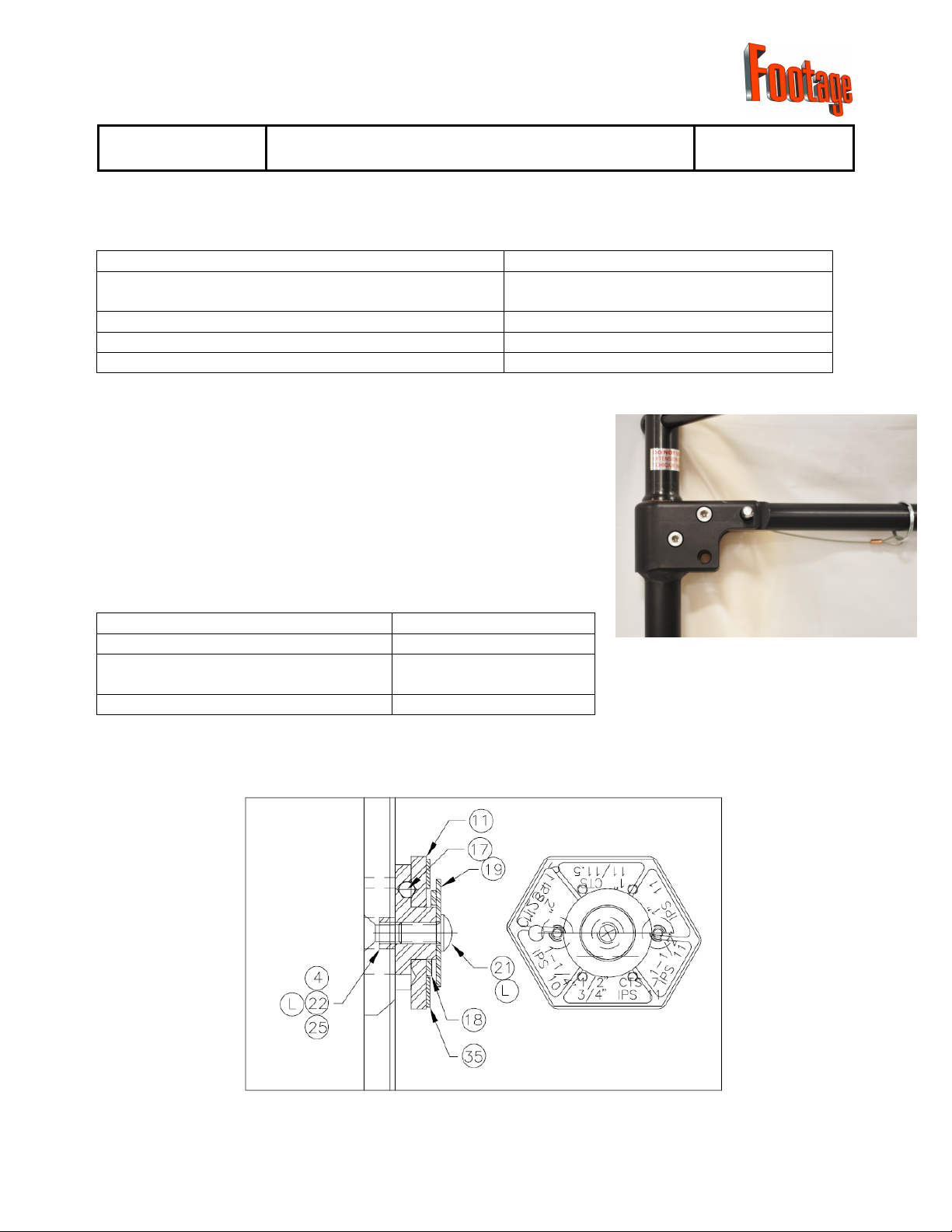
4) Set the gauge plate stop on the side of the unit
to the proper pipe size and SDR setting required. The
gauge plate assembly may be stiff, it will be easier to
set if the gauge plate is pulled out slightly from body
of tool while turning it. If the detent action is not
positive, the gauge plate mechanism requires
cleaning and/or service. Position the arrow on the
gauge plate setting so that it faces the bronze barrel
nut as shown at right. (Figure 2)
Figure 2

ECN 1813 C200 (1/2 TO 2 in.) EXTENDED REACH
SQUEEZE OFF TOOL FOR PE PIPE Page 3 of 7
Figure 4
Figure 3 Fi
g
ure 5
5) Place the head of the tool on the pipe such that the pipe runs between the squeeze jaws. Note
that the aluminum handle is parallel to the pipe as shown in figure 3. Place the tool centrally on
the pipe using the centering springs to assist in location as shown in figure 4. As a rough guide
note that the inside edge of the pipe is in approximate alignment with the side of the tool body
as shown in figure 5. Make sure that the pipe stays in contact with both centering springs.
B) Squeezing the Pipe
1) Advance the squeeze bar by turning the drive screw clockwise until the lower jaw starts to touch
the pipe. During the “squeeze-off” operation keep tool at right angles to the pipe.
2) The rate of squeeze is very important in minimizing the damage to the pipe walls. Advance the
squeeze no faster than 2” per minute. Increase this time in colder weather below 32°F (0°C).
Consult your local utility as to their specific procedure for this operation. As the pipe is

ECN 1813 C200 (1/2 TO 2 in.) EXTENDED REACH
SQUEEZE OFF TOOL FOR PE PIPE Page 4 of 7
squeezed the centering springs will relax and fold out of the
way of the pipe. (Figure 6)
3) Continue slowly squeezing until the gauge plate stops come
in contact with the bronze barrel nut. (See Figure 6) DO NOT
CONTINUE SQUEEZING ONCE THE GAUGE STOPS
HAVE BEEN REACHED OR TOOL DAMAGE MAY
RESULT. Keep in mind; it may not be necessary to
squeeze the pipe all the way to the gauge stops to obtain
satisfactory flow control. NEVER USE EXTENSIONS ON
THE “T” HANDLE OR RATCHET TO GET MORE
SQUEEZE, AS TOOL DAMAGE MAY RESULT.
C) Releasing the Pipe
1) To avoid any damage to the plastic pipe, it is critical that a
slow release rate be achieved. A release rate of ½” (12.5 mm)
per minute is recommended. This time allows for the controlled rebound of the plastic,
decreasing the chances of slow crack propagation. Below 32°F (0°C), the release rate should
be slower. Consult your local utility as to their specific procedure for this operation.
2) Unscrew the powerscrew slowly, not exceeding the release rate. Continue to open the tool at
this rate until it can be removed from the pipe.
3) WARNING: Do not continue to unscrew the tool past the point that the barrel
nut comes in contact with the bottom of the cut-out in the tool head side plate,
or damage may result.
D) Re-rounding of Pipe
1) This tool can not be used for re-rounding pipe due to the length of the handle. It should also be
noted that PE pipe rebounds on it’s own to its near original shape very well. Squeeze points on
the pipe are typically marked in some fashion for future reference. Consult your local utility as
to their specific procedure for this operation.
E) WARNING
1) Do not exceed the recommended squeeze and release rates. Temperatures below
32°F (0°C) will require slower squeeze and release rates. Release is more critical
than squeeze; thus slower rates are required.
WARNING
2) When performing a squeeze, stay at least 3 pipe diameters away from fittings, fusion
areas and previously squeezed areas.
WARNING
3) To ensure the removal of any static electric charge buildup, ensure the grounding
system is properly planted in the soil. Your tool can easily be fitted with a grounding
spike if not so equipped. Contact your FOOTAGE TOOLS dealer for installation
instructions and parts.
Figure 6

Important Notice
If you experience difficulty obtaining flow control when
squeezing HDPE pipe, we recommend you perform a
double squeeze and vent to atmosphere.
Please consult your local Utility for their specific
operating procedure.
ECN 1813 C200 (1/2 TO 2 in.) EXTENDED REACH
SQUEEZE OFF TOOL FOR PE PIPE Page 5 of 7
F) Maintenance
Ensure the tool is in good operating order by routinely inspecting the following points prior to use:
Inspect the centering springs for damage. Replace as needed
Inspect the gauge plate assembly for positive
detent action Clean, repair or replace parts as needed
Inspect the grounding spike connections. Replace as needed
Inspect the tool for free operation. Clean, repair or replace parts as needed
Inspect the squeeze jaws for surface damage. Replace as needed
G) Service
Partially disassemble the tool by removing the screw indicated in
figure 7. This will allow the power screw to be unthreaded from
the barrel nut and lifted out from the top of the tool. The barrel nut
is then pulled out from the side of the tool body. This in turn will
free the active jaw for removal from the tool head. Should your
tool require more extensive service work please refer to the
attached drawing in the next section (H) for assembly instructions
and parts information.
Inspect the power screw for dirt. Clean and lubricate.
Inspect the tool head cavity for dirt. Clean as needed
Inspect the power screw thread for
damage. Repair or replace as
needed
Inspect the barrel nut for damage. Replace as needed
Figure 7
Detail of Gauge Plate Assembly and Installation

DETAIL A
SCALE .5
1
1
2
2
3
3
4
4
A A
B B
C C
D D
SHEET 1 OF 1
DRAWN
CHECKED
QA
MFG
APPROVED
nguyenj
nguyenj 7/7/2009
DWG NO
C200-A2
TITLE
SIZE
C
SCALE
REV
D
A
Parts List ITEM
DESCRIPTION
PART NUMBER
QTY 36LABEL - OWNERS MANUALLABEL-009135GAUGE PLATE LABELC125-14134FOOTAGE TOOLS LABEL - NEWLABEL-012
133LABEL, DO NOT USE EXTENSIONLABEL-001
132BOX FOR C200BOX-C200131STOPPERC200-21130GOURND SPIKE ASMC615-A115
129
BUSHING, FLANGED 1"
99-178-16-2008
128
FHCS 10-24 X 1/2
99-110-01-9008227
FHCS 3/8-16 X 3/4
99-110-00-0612926SHOULDER BOLT 3/8 X1 1/499-114-01-0512225CHROME BALL99-157-00-0006
124SPRING WASHER W-385C200-25123BHCS 10-32 X 199-105-01-9004422BHCS 1/4-20 X 1/299-104-01-0408
121
HHCS 7/16 X 3/4
99-100-00-0706
120END WASHERC110-17119TORQUE BAR ASMC105-42118DOWEL PIN 3/8 X 1 3/499-165-00-2428
417
SHSS 1/4-20 X 1
99-150-S0-0416
116
ROLL PIN 1/8 X 1/2
99-163-00-0808115
WASHER1/4 (FASTENAL #33207)
99-145-00-0041114
KEY RING 1.5" O.DC200-22
113HITCH PIN & LANYARDC200-19
112GRIP WORKS #GP-6C200-23111GAUGE PLATEC125-12110SPRING, SPEC #E0240-034-2500C200-2029WEAR RINGC200-15
18BOTTOM JAWC200-1217BARREL NUTC200-1616
HANDLE BAR
C200-09
15
TOP JAWC200-06
14GAUGE PLATE HUBC200-1413SIDE PLATEC200-0212POWER TUBE WELDMENTC200-W02
11
POWER SCREW WELDMENTC200-W01
1
15
25
16
3
28
3
27 34
13
14
19
6
12
1
33
18
5
23
10
87
9
2
2
1
2
17
21
20
26
22
11
4
29
30
31
FOOTAGE TOOLS INC.
C200-A1 ASSEMBLY DWG
2" REM. SQUEEZE OFF TOOL
NTS
REMOVE ALL SHARP CORNERS
UNLESS SPECIFIED OTHERWISE
35
24
36

ECN 1813 C200 (1/2 TO 2 in.) EXTENDED REACH
SQUEEZE OFF TOOL FOR PE PIPE Page 7 of 7
I) Footage Tools Limited Warranty
FOOTAGE TOOLS INC, hereinafter sometimes referred to as “Manufacturer” warrants each
new industrial product of its own manufacture to be free from defects in material and workmanship,
under normal use and service for one full year after delivery to the end user. Warranty is void
unless warranty registration card is completed in full and returned to FOOTAGE TOOLS INC
within thirty days from the date of purchase. This warranty and any possible liability of
FOOTAGE TOOLS INC hereunder are in lieu of all other warranties, expressed, implied, or
statutory, including, but not limited to, any warranties of merchantability or fitness for a particular
purpose.
The parties agree that the Buyers SOLE AND EXCLUSIVE REMEDY against Manufacturer,
whether in contract or arising out of warranties, representations, instructions, or defects shall be for
the replacement or repair of defective parts as provided herein. In no event shall Manufacturers
liability exceed the purchase price of the product. The Buyer agrees that no other remedy
(including, but not limited to, in incidental or consequential loss) shall be available to him. If during
the warranty period, any product becomes defective by reason of material or workmanship and
Buyer immediately notifies Manufacturer of such defect, Manufacturer shall, at its option, supply a
replacement part or request return of the product to its plant in Toronto, Canada. No parts shall be
returned without prior written authorization and a return goods authorization number from
Manufacturer, and this Warranty does not obligate the Manufacturer to bear any transportation
charges in connection with the repair or replacement of defective parts. The Manufacturer will not
accept any charges for labour and/or parts incidental to the removal or remounting of parts repaired
or replaced under this Warranty.
This Warranty shall not apply to any part or product which shall have been installed or
operated in a manner not recommended by FOOTAGE TOOLS INC, nor to any part or product
which shall have been neglected, or used in any way which, in the manufacturers opinion,
adversely affects its performance; nor negligence of proper maintenance or other negligence, fire,
or other accident: nor if the unit has been altered or repaired outside of a FOOTAGE TOOLS INC
authorized dealership in a manner of which, in the sole judgement of FOOTAGE TOOLS INC
affects its performance stability or reliability: nor to any product in which parts not manufactured or
approved by FOOTAGE TOOLS INC have been used, nor to normal maintenance services or
replacement of normal service items. Equipment and accessories not of our manufacture are
warranted only to the extent of the original Manufacturers Warranty and subject to their allowance
to us, if found to be defective by them.
The original purchaser, user is responsible for “downtime” expenses and all business costs
and losses resulting from a warrantable failure. FOOTAGE TOOLS INC specifically disclaims any
responsibility for any damages of any kind or description, whether to property or person, in any way
connected with or arising out of the use of FOOTAGE TOOLS INC products.

Tool Registration Card
Warranty registration
now available online.
Please visit
www.footagetools.com
and click on
‘warranty registration’.
Model:
S/N:
IMPORTANT NOTICE
IMPORTANT NOTICE
Vaughan, Ontario
54 Audia Crt. Unit #1
Toll Free: 1-888-737-3668
www.footagetools.com
Table of contents
Other FOOTAGE Tools manuals


