manuals.online logo
Brands
  1. Home
  2. •
  3. Brands
  4. •
  5. FOR-A
  6. •
  7. Control Unit
  8. •
  9. FOR-A USF-212S User manual

FOR-A USF-212S User manual

1. Installing the AC Cord Retaining Clip
Secure the AC cord with the supplied ladder strap/retaining clip assembly to prevent accidental disconnection from the USF-212S.
Apply before mounting on the rack.
1) Wrap the retaining clip around the AC cord. (with the anchor of the ladder strap toward the unit.)
2) Insert the anchor into the hole next to the AC IN socket.
3) Lightly fasten the clip around the AC cord.
4) Plug in the power cord.
5) Slide the clip on the ladder strap toward the plug.
6) Fasten the clip tightly.
7) Gently pull on the AC cord to ensure it is secured.
2. Opening the Front Panel
The Front panel may be difficult to open if the USF frame is placed on a desk, and may be damaged the front panel if it is forced
to open. Perform the following steps after setting the frame in a rack.
The OPEN alarm will sound every 30 seconds. It continue sounding after 5 minutes. In case of the power is on, complete
the procedure in a short period of time.
3. Detaching the Front Panel
Handle the front panel carefully so as not to bend the rails.
IMPORTANT
After the front panel is installed, the ALARM LED on the front panel will light in the following order.
DC1 → DC2 → FAN → TEMP
When the ALARM LEDs not lighting in the above order indicates the front panel has not been installed properly. Re-install the
front panel.
4. Front Interior
The slot configuration as shown below is revealed when the front panel is removed.
No.
Slot Type
Description
(1)
Power Supply 1 slot
Dedicated power unit is installed in this slot as standard. Power is supplied when the
switch is turned on.
(2)
Power Supply 2 slot
Slot for redundant power supply USF-212PS. Redundant operation available when
optional USF-212PS is installed. A blank panel will otherwise cover the slot.
(3)
Control module slot
Fan module slot. Enables you to monitor power supply and fan states via SNMP from
back connector LAN A and alarm output via GPI. LAN1 and LAN2 are not applicable.
(4)
Expansion slot
Not used.
(5)
USF module slot
Dedicated USF module slots. (Front USF modules)
For details on module operation, refer to the respective operation manuals.
USF-212S
USF-212S Packing List:
USF-212S (1 unit)
AC Cable (1 set, including AC Cord Retaining Clip)
CD-ROM (PDF Operation Manual)
2)
4)
3)
5)
6)
(1)
(2)
(3)
(4)
(5)
The front panel rails can
be tilted down.
Pull out the front panel.
Quick Setup Guide
TEMP
FAN
DC2
DC1
ALARM
ON
POWER
USF-212
UNIVERSALSYSTEMFRAME
LOCK LOCK
Loosen the two thumbscrews of the front
panel by turning them counterclockwise.
TEMP
FAN
DC2
DC1
ALARM
ON
POWER
USF-212
UNIVERSALSYSTEMFRAME
LOCK LOCK
Pull out the front panel using the pull
handles. The fan stops while the
front panel is open.
The front panel can
be detached by
gently pushing both
rails inward.
Fully draw out the front panel.
5. USF Module Installation
USF Modules can be installed into any free slot. If multiple free slots exist, do not install modules side-by-side but leave slots open to
prevent overheating and facilitate signal connection from the rear panel.
The procedure for installing the USF module in Slot 1 is described below as an example.
Installing a USF Rear Module
Installing a USF Front Module
Make sure to install the front module after installing the rear module.
1) SLOT 1 is the top slot in the right block of the front panel. (Refer to Sec. 4-5. “Slot Number.”)
2) Set the module on the guide rail and carefully insert the module slowly.
3) Push the handle until the front module clicks into the connectors.
Inserting the module by pressing on other than the handle may damage some parts on the PCB.
NOTE
USF Modules come as front and rear sets. Be sure to install set modules into the same (front and rear) slot
locations.
Make sure to install the rear module first, then install the front module.
Install blank panels over free slots to prevent foreign material from entering and overheating the chassis.
IMPORTANT
Beware of the occurrence of electrical breakdown in USF Modules.
Wear an antistatic wrist strap or equivalent to equalize the electrical potential of the USF-212S unit and the worker’s
body. Do not touch the PCB wiring or parts legs directly with your fingers while working.
Each USF Module can be installed and uninstalled while the power is on in case of emergency. Shut down the
power for non-emergency work.
When front module is being installed / uninstalled while the power is on, the front panel is in open state. The fan
will stop during the procedure, so it is essential to complete the installation within a short period and to close the
front panel immediately.
Be sure to shut down the power to install and uninstall a control module.
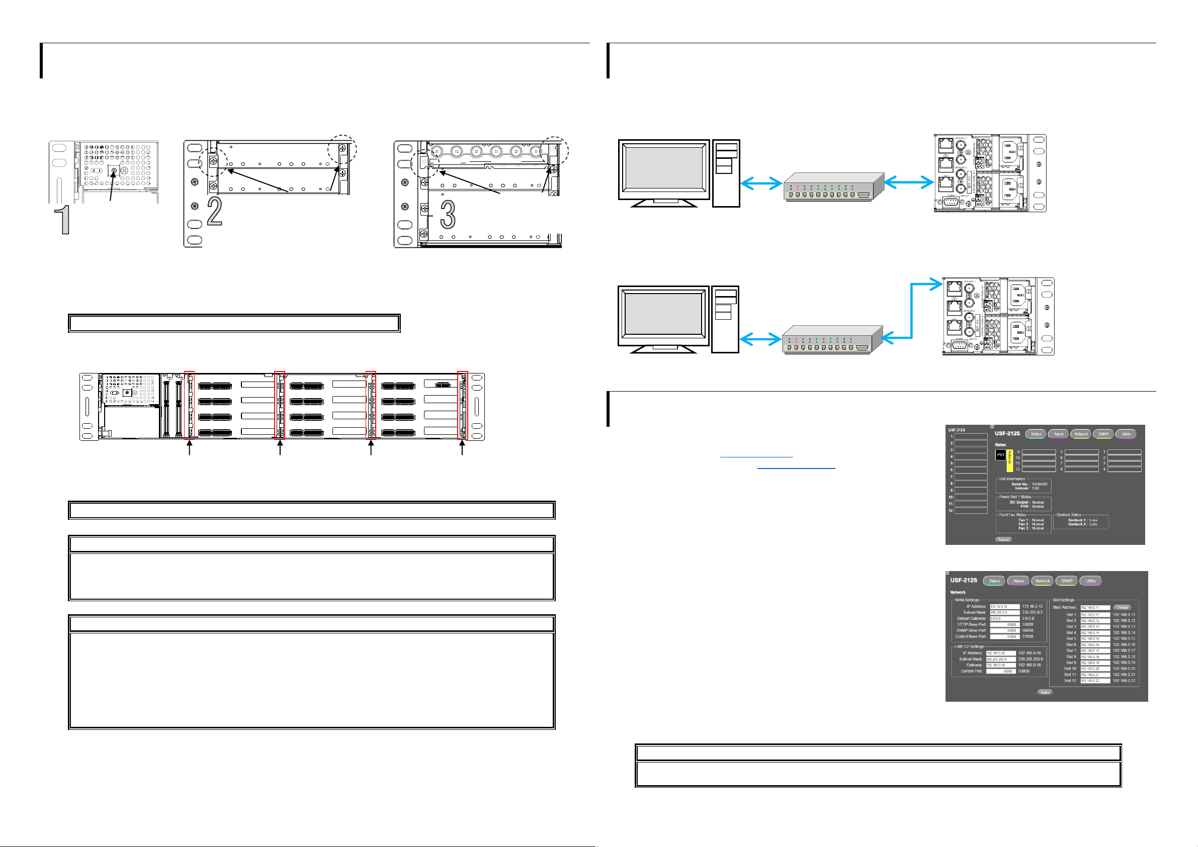
6. Connecting USF-212S to a PC
When USF-212S is network connected via network to a PC, operation can be monitored on SNMP manager using a web browser, and
GPIO alarm setting can be entered. There are two ways to connect USF-212S to a PC; using LAN A or LAN 1/2 port. Select a suitable
port in accordance with system configuration.
LAN A port connection
LAN 1/ LAN2 port connection
Connect to LAN1 or LAN2 port on the rear panel. (Connection to LAN1 port is shown in the drawing below.)
7. Network Default Setting
Open the web browser of the PC and input address.
Connecting to LAN A: http://172.16.0.10/ (Factory Setting)
Connecting to LAN 1 or LAN 2: http://192.168.0.10/ (Factory Setting)
A status page as shown opens on the web browser when connection is
established.
IP Address Change
1) Click the Network tab.
2) Input new IP address into the IP Address box of WAN Settings to change
LAN A IP address.
Input new IP address into the IP Address box of LAN 1/2 Settings to change
LAN 1/2 IP address.
3) A confirmation message window opens when you click Apply.
Click OK in the confirmation window.
4) Click Utility tab, then click Restart.
Click OK when the restart confirmation window opens. USF-212S restarts. The new setting is reflected after the restart.
NOTE
IP addresses are assigned to respective USF-212S modules installed. Refer to USF-212S operation manual Sec.10
“USF-212S WEB GUI” for details on setting IP addresses.
Guide Rail
Guide Rail
Guide Rail
Guide Rail
Open the front panel
and shut down the
USF-212S power
supply.
Slot 1 is the top slot in the left module
block in the rear panel. Remove the
blank panel by detaching the two
screws on both ends. Keep the blank
panel and screws in a safe place after
removal.
3G/HD/SD SDI IN
USF-1043FS
1 2 1 2 3 4
3G/HD/SD SDI OUT
Insert the rear module into
the slot and fasten both
screws.
LAN A IP Address
Factory Setting
172.16.0.10
LAN A LED
Green Lit: Connected
Orange Flashing: Transmitting and
receiving data
USF-212S Rear
Web Browser
SNMP Manager
LAN 1/2 IP Address
Factory Setting
192.168.0.10
Slot 1 to 12 IP Address
Factory Setting
192.168.0.11 to
192.168.0.22
LAN 1/2 LED
Green Lit: Connected
Orange Flashing: Transmitting and
receiving data
USF-212S Rear
Web Browser
SNMP Manager

Other FOR-A Control Unit manuals

FOR-A FA-10RU User manual

FOR-A

FOR-A FA-10RU User manual

FOR-A HVS-AUX16B User manual

FOR-A

FOR-A HVS-AUX16B User manual

FOR-A HVS-AUX16A User manual

FOR-A

FOR-A HVS-AUX16A User manual

FOR-A MFR-16 User manual

FOR-A

FOR-A MFR-16 User manual

FOR-A HVS-2000-2SI User manual

FOR-A

FOR-A HVS-2000-2SI User manual

Popular Control Unit manuals by other brands

Elatec TWN4 MultiTech 2 HF user guide

Elatec

Elatec TWN4 MultiTech 2 HF user guide

ICP DAS USA ECAT-2011H user manual

ICP DAS USA

ICP DAS USA ECAT-2011H user manual

Axiris ArduIN-9 user manual

Axiris

Axiris ArduIN-9 user manual

SII TMI NE20 Technical guide & parts catalogue

SII

SII TMI NE20 Technical guide & parts catalogue

Samsung AVR-M100FHAX installation manual

Samsung

Samsung AVR-M100FHAX installation manual

RTI PCM-4 Quick reference guide

RTI

RTI PCM-4 Quick reference guide

tozen PRV-CPR instruction manual

tozen

tozen PRV-CPR instruction manual

Savio K6002 operating manual

Savio

Savio K6002 operating manual

Viessmann 5546 Operation manual

Viessmann

Viessmann 5546 Operation manual

ADTRAN Total Access 1500 Installation and Maintenance

ADTRAN

ADTRAN Total Access 1500 Installation and Maintenance

Kramer RC-7RL user manual

Kramer

Kramer RC-7RL user manual

Elvaco CMi Series user manual

Elvaco

Elvaco CMi Series user manual

GEM 411 Installation, operating and maintenance instructions

GEM

GEM 411 Installation, operating and maintenance instructions

Ross Vision 4800DR-324-02 installation guide

Ross

Ross Vision 4800DR-324-02 installation guide

Honeywell Temaline TK-S014 installation manual

Honeywell

Honeywell Temaline TK-S014 installation manual

Neoway N20 AT Command manual

Neoway

Neoway N20 AT Command manual

Rockwell Automation MAO04NND user manual

Rockwell Automation

Rockwell Automation MAO04NND user manual

Maxsys PC4204CX installation instructions

Maxsys

Maxsys PC4204CX installation instructions

manuals.online logo
manuals.online logoBrands
  • About & Mission
  • Contact us
  • Privacy Policy
  • Terms and Conditions

Copyright 2025 Manuals.Online. All Rights Reserved.