2
2.3 Hazardous environment and media:
The product has to be protected from hazardous environment and check to ensure that
no hazardous liquids or gases pass through the product.
2.4 Depressurizing of systems and normalizing of temperature:
Ensure isolation and safety venting of any pressure to the atmospheric pressure. Even if
the pressure gauge indicates zero, do not make an assumption that the system has been
depressurized. To avoid danger of burns allow temperature to normalize after isolation.
2.5 Tools and consumables:
Ensure you have appropriate tools and / or consumables available before starting the
work. Use of original Forbes Marshall replacement parts is recommended.
2.6 Protective clothing:
Consider for the requirement of any protective clothing for you/ or others in the vicinity for
protection against hazards of temperature (high or low), chemicals, radiation, dangers to
eyes and face, noise and falling objects.
2.7 Permits to work:
All work to be carried out under supervision of a competent person. Training should be
imparted to operating personnel on correct usage of product as per Installation and
Maintenance instruction. “Permit to work” to be complied with (wherever applicable), in
case of absence of this system a responsible person should have complete information
and knowledge on what work is going on and where required, arrange to have an
assistant with his primary goal and responsibility being safety. “Warning Notices” should
be posted wherever necessary.
2.8 Handling:
There is a risk of injury if heavy products are handled manually. Analyze the risk and use
appropriate handling method by taking into consideration the task, individual, the
working environment and the load.
2.9 Freezing:
Provision should be made to protect systems which are not self-draining, against frost
damage (in environment where they may be exposed to temperatures below freezing
point) to be made.
2.10 Product Disposal:
It is necessary to dispose this product only in accordance with local regulations at the
authorized, qualified collecting point specified for equipment’s and its parts—Please
refer the part details mentioned in the material table of this manual. Please follow all
waste disposal guidelines (Management & Handling) as published by local governing
authorities in India & abroad
2.11 Returning products:
Customers and Stockist are reminded that, when returning products to Forbes Marshall
they must provide information on any hazards and the precautions to be taken due to
contamination residues or mechanical damage which may present a health, safety or
environmental risk.
This information must be provided in writing including Health and Safety data sheets
relating to any substances identified as hazardous or potentially hazardous.
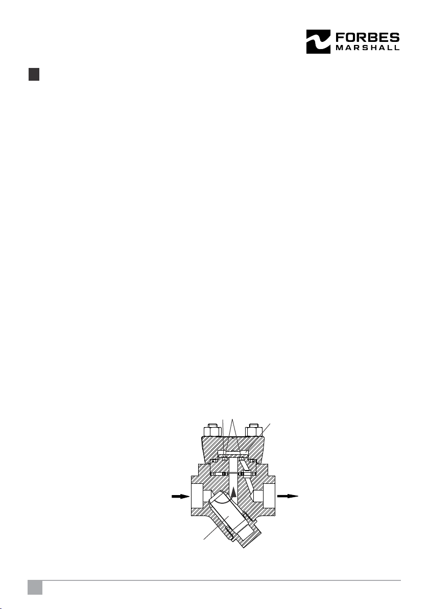
Forbes Marshall Thermodynamic Trap