Forbes Marshall SOFT31 Manual

Single Orifice Float Trap With SLR and/or TV
SOFT31 (DN15-25)
Installation and Maintenance Manual
Energy Conservation | Environment | Process Efficiency www.forbesmarshall.com

1. Preface .................................................................................1
2. Important Safety Notes ........................................................1
3. Brief Product Information ....................................................3
4. Product Working Principle ...................................................5
5. Installation Guidelines .........................................................6
6. Start-up and Commissioning ...............................................7
7. Maintenance Guidelines .....................................................8
8. Troubleshooting .................................................................11
9. Available Spares ................................................................13
10. Warranty Period .................................................................14
Table of Contents
PLEASE NOTE - Throughout this manual this cautionary symbol is used to
describe a potential damage or injury that might occur if the safety
considerations are overlooked. This symbol denotes CAUTION, WARNING or
DANGER.
Single Orifice Float Trap With SLR and/ or TV

1
Preface:1.
This manual is intended for anyone using, commissioning, servicing, or disposing the below
mentioned products safely and efficiently.
Single Orifice Float Trap With SLR and/ or TV [SOFT31 (DN15-25)]
Sizes: DN15 (1/2''), DN20 (3/4''), DN25 (1'')
PLEASE NOTE:
Throughout this manual the following cautionary symbol is used to describe a potential damage
or injury that might occur if the safety considerations are overlooked.
2. Important Safety Notes:
Read this section carefully before installing/operating/maintaining the product. The
precautions listed in this manual are provided for personnel and equipment safety.
Furthermore, Forbes Marshall accepts no responsibility for accidents or damage
occurring as a result of failure to observe these precautions. Note that the product is
designed to perform for non-contaminated fluids only. A contamination in the form of
chemical, foreign particle etc. can lead to problem with product performance and life
of the product.
If these products in compliance with the operating instructions are, properly installed,
commissioned, maintained and installed by qualified personnel (refer Section 2.7) the safety
operations of these products can be guaranteed. General instructions for proper use of tools and
safety of equipments, pipeline and plant construction must also be complied with.
2.1 Intended use:
Check if the product is suitable for intended use/ application by referring to the installation
and maintenance instructions, name plates and technical information sheets.
i) The product is suitable for use as defined in the technical information sheet. In case the
need arises to use the product on any other fluid please contact Forbes Marshall for
assistance.
ii) Check for the suitability in conformance to the limiting conditions specified in technical
information sheet of the product.
iii) The correct installation and direction of fluid flow has to be determined.
iv) Forbes Marshall products are not intended to resist external stresses, hence necessary
precautions to be taken to minimize the same.
2.2 Accessibility and Lighting:
Safe accessibility and working conditions are to be ensured prior to working on the
product.
SOFT31(DN15-25)

2
2.3 Hazardous environment and media:
The product has to be protected from hazardous environment and check to ensure that no
hazardous liquids or gases pass through the product.
2.4 Depressurizing of systems and normalizing of temperature:
Ensure isolation and safety venting of any pressure to the atmospheric pressure. Even if the
pressure gauge indicates zero, do not make an assumption that the system has been
depressurized.
To avoid danger of burns allow temperature to normalize after isolation.
2.5 Tools and consumables:
Ensure you have appropriate tools and / or consumables available before starting the work.
Use of original Forbes Marshall replacement parts is recommended.
2.6 Protective clothing:
Consider for the requirement of any protective clothing for you/ or others in the vicinity for
protection against hazards of temperature (high or low), chemicals, radiation, dangers to
eyes and face, noise and falling objects.
2.7 Permits to work:
All work to be carried out under supervision of a competent person. Training should be
imparted to operating personnel on correct usage of product as per Installation and
Maintenance instruction. “Permit to work” to be complied with (wherever applicable), in
case of absence of this system a responsible person should have complete information and
knowledge on what work is going on and where required, arrange to have an assistant
with his primary goal and responsibility being safety. “Warning Notices” should be posted
wherever necessary.
2.8 Handling:
There is a risk of injury if heavy products are handled manually. Analyze the risk and use
appropriate handling method by taking into consideration the task, individual, the working
environment and the load.
2.9 Freezing:
Provision should be made to protect systems which are not self-draining, against frost
damage (in environment where they may be exposed to temperatures below freezing
point) to be made.
2.10 Product Disposal:
It is necessary to dispose this product only in accordance with local regulations at the
authorized, qualified collecting point specified for equipment’s and its parts—Please refer
the part details mentioned in the material table of this manual. Please follow all waste
disposal guidelines (Management & Handling) as published by local governing authorities
in India & abroad
2.11 Returning products:
Customers and Stockist are reminded that, when returning products to Forbes Marshall
they must provide information on any hazards and the precautions to be taken due to
contamination residues or mechanical damage which may present a health, safety or
environmental risk.
This information must be provided in writing including Health and Safety data sheets
relating to any substances identified as hazardous or potentially hazardous.
Single Orifice Float Trap With SLR and/ or TV

3. Brief Product Information:
3.1 Description:
The Forbes Marshall Single Orifice Float Trap, SOFT31, is a cast iron single orifice float trap
available with an integral automatic air venting facility. It is available with horizontal or vertical
connections with flow downwards. As an alternative a manual needle valve can be added and
used as a steam lock release.
3.2 Sizes and Pipe Connection:
DN 15, 20 and 25 Screwed BSPT/NPT/BSP.
Flange connection: #125, PN16
Note: Available with IBR certificate on request.
3.3 Available Types:
SOFT31-T TV with Thermostatic air Vent (TV)
SOFT31-S with Steam Lock Release (SLR)
SOFT31-ST combined TV and SLR
3.4 Limiting Conditions :
3
SOFT31(DN15-25)
Screwed Version # 125 Flange PN16 Flange
PMA Maximum 13 bar g at 10.1 bar g at 13 bar g at
Allowable pressure 220°C 180°C 180°C
TMA Maximum 220°C at 180°C at 180 at
Allowable temperature 13 bar g 10.1 bar g 13 bar g
PMO Maximum 13 bar g 10.2 bar g 13 bar g
Operating pressure
TMO Maximum 220°C at 180°C at 180°C at
Operating temperature 13 bar g 10.1 bar g 13 bar g
Minimum Operating 0°C 0°C 0°C
Temperature
PMX Maximum differential pressure
SOFT31-4.5 4.5 bar g
SOFT31-10
SOFT31-13
10 bar g
13 bar g
Cold hydraulic test pressure 26 bar g

4
1
2
5
7
411
10 3
21
19
20
Figure1: Single Orifice Float Trap with SLR and / or TV
Material:
Sr.No Part Material Standard
1Cover Cast iron IS 210 FG260
2Cover bolts Carbon steel ASTM A193 Gr.B7
3Cover gasket Asbestos free synthetic fibre
4Base Cast iron IS 210 FG260
5Main valve seat Stainless steel type 304 ASTM A743, Gr.CA40
6Main valve seat gasket
7Main valve assembly screws Stainless steel type 304 IS 1364
8Ball float and lever Stainless steel type 304 ASTM A240
9Air vent element Stainless steel type 316 ASTM A240
10 SLR unit Stainless steel type 410 ASTM A276
11 SLR unit gasket Stainless steel type 304 ASTM A240
12 Pivot frame type 304 Stainless steel ASTM A240
13 SLR seal Graphite
Single Orifice Float Trap With SLR and/ or TV
Temperature °C
Pressure bar g
Steam
saturation
0
0
50
100
150
200
220
246810 12 13
3.5 Operating Range:
A
D
B
C
E
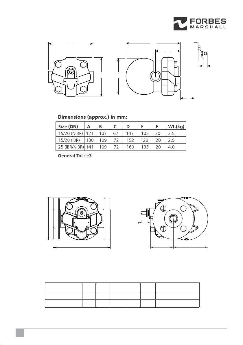
Dimensions (approx.) in mm:
General Tol : ±3
Size (DN) A B C D E Wt.(kg)
15/20 150 55 127 109 120 4.5
25 160 97 90 120 135 6.5
(Flanged Version)
(Flanged Version #125 & PN16)
BB1
C
F
SOFT31
AD
E
SOFT31
3.6 Product Dimension and Drawing:
5Single Orifice Float Trap With SLR and/ or TV
Figure 2: Dimensional Drawing of SOFT31
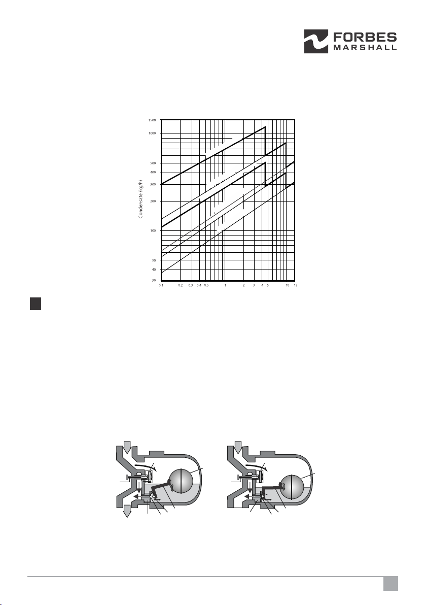
4. Product Working Principle: (Refer to Figure 3)
Figure 3 shows a simple float trap operational representation. A float trap works on the Buoyancy
Principle. Condensate enters the trap body and raises the float (1). The position of the float (1) depends
upon the level/load of condensate (flowrate). The float trap continues to discharge condensate
continuously and doesn't allow back up of condensate as long as the load is within the discharge
capacity. When the condensate load drops, the float (1) lowers in position and closes the outlet valve (3)
with the ball (6) resting on the orifice (7).
SLR (4) is a needle valve which releases steam that can steam lock the trap during start-up or in
operation if the steam reaches the trap before the condensate.
On the start up the air present in the pipeline/process equipment is released through the thermostatic
vent (5).
Figure 3: Single Orifice Float trap working
*The trap in the figure 3 shows a TV+SLR assembly. SOFT31(DN15-25) also comes with only TV or SLR assembly.
5
4
376
2
OUTLET
Pivot
1
INLET
5
4
376
2
OUTLET
Pivot
1
INLET
3(a) Trap Discharge Open 3(b) Trap Discharge Closed
6
3.7 Capacity Chart:
SOFT31(DN15-25)
DN 25 SOFT31-4.5
DN 25 SOFT31-10
DN 15 & 20 SOFT31-4.5
DN 25 SOFT31-13
DN 15 & 20 SOFT31-10
DN 15 & 20 SOFT31-13
Differential pressure bar g (x100 = kPa)

Figure 4: Single Orifice Float trap module
*Typical/ Representative Installation and may vary based on application and site
Item No. Description
1Spring Loaded Check Valve
2,6 Stop Valve
3 View Glass
4 Single Orifice Float Trap
5 Strainer
Figure 5: Single Orifice Float trap name plate
6. The arrow on the casting should be in the direction of the flow.
4. If the trap is to discharge to atmosphere ensure it is to a safe place, the discharging
fluid may be at a temperature of 100 °C (212°F).
5. Install the trap such that the arrow on the name plate points downward to achieve proper
orientation of the trap.
5. Installation Guidelines: (Refer to Figure 4, 5, and 6)
Note: Before implementing any installations observe the 'Important Safety notes” in
section 2. Referring to the Installation and Maintenance Instructions, name-plate and
Technical Information Sheet, check that the product is suitable for the intended
installation.
Installation checks and Steps:
1. Check the correct installation location/position and the direction of fluid flow.
2. Remove protective covers from all connections where appropriate, before installation.
3. Ensure the availability of all components as shown in Figure 5, to ensure the operation of the
trap.
7Single Orifice Float Trap With SLR and/ or TV
4. If the
trap is
to
discha
rge to
atmos
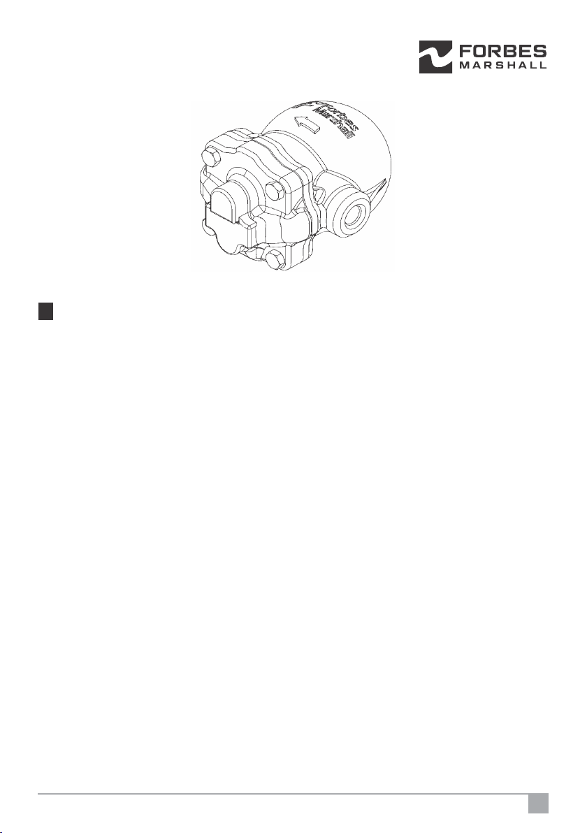
Figure 6: Cover casting with the arrow
6. Start-up and Commissioning:
6.1 Flushing of Lines (Refer to Figure 4)
As part of pre-installation all fluid handling equipment particularly piping should be
thoroughly cleaned of scale and the internal debris which accumulates during
construction. This is accomplished by blowing or flushing with air, steam, water and other
suitable medium.
Follow these steps to carry out the flushing.
1. Close the stop valve (2) and open the bypass stop valve (6).
2. Let the condensate drain for at least 10-15 minutes or until clear condensate starts
coming out, whichever is earlier.
3. Now slowly close the bypass stop valve (6) and open the stop valve (2).
6.2 Commissioning :(Refer to Figure 4)
After installation or maintenance ensure that the system is fully functioning by confirming
condensate is passing through it.
i) After flushing of lines is complete, ensure stop by-pass valve (6) closed and stop
valve (2) opened.
ii) Check for leaks and attend if any.
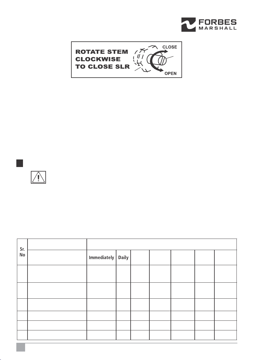
6.3 Setting of steam lock release (SLR) : (Refer to Figure 7)
Only SLR Assembly:
1. Loosen the gland nut (1) by one thread
2. Rotate the stem (2) in clockwise direction. This moves the stem (2) towards SLR seat.
3. Once the stem touches the SLR seat, rotate the stem (2) in anti-clockwise direction by
th
1/4 of a turn.
8
SOFT31(DN15-25)
7. Maintenance Guidelines:
Before undertaking any maintenance on the product it must be isolated from both
supply line and return line and any pressure should be allowed to safely normalise to
atmosphere. The product should then be allowed to cool. With suitable isolation
repairs can be carried out with the product in the line. When re-assembling, make sure
that all joint faces are clean. Once completed open isolation valves slowly and check for
leaks.
7.1 Routine and preventive maintenance:
Please refer to the maintenance schedule mentioned in the table below to undertake
routine maintenance of the trap.
Sr.
No
Parameters to be checked Frequency for checking and maintaining
Single orifice float trap Immediately Daily Weekly Monthly Quarterly Half
yearly Annually
1Test medium pressure SOFT31
(3.5 barg to 17.5 barg) Y
2Repair / Replace SOFT31 -
when testing shows leaks Y
3Clean strainers of SOFT31 Y
4Clean internals of SOFT31 Y
5Visual inspection for leakages Y
6 Arresting any other leaks Y
Figure 7: SLR setting for only SLR and SLR+TV configuration
SLR+TV Assembly:
Loosen the gland nut by one thread. Rotate the stem in anti-clockwise direction. This moves
the stem towards thermopod. Once the stem touches the thermopod ball, rotate it further
th
by 1/4 of a turn.
4. Check for normal discharge pattern and leaks if any.
Note: The SLR unit should only be used to prevent 'steam locking' and therefore is
designed to pass a small amount of steam, it is not recommended that the SLR be
left in the fully open condition as this may lead to premature trap failure and more
frequent maintenance schedules.
1
2
9Single Orifice Float Trap With SLR and/ or TV
7.2 Tool Kit:
To carry out any maintenance on the SOFT31 please use the tools mentioned below:
7.3 Recommended tightening torques:
Cover Bolts(1) Base(2)
Air Vent Assembly(12)
Cover(11)
Metal Gasket(8)
Main Valve Seat(7)
Pivot Frame(6)
Pivot Pin(3)
Set Screws(5)
Gasket(10)
Float(4)
Steam Lock Release Unit
(10)
Main Valve Assembly
(9)
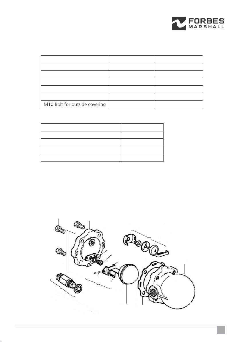
7.4 Maintaining / Replacing the main valve assembly : (Refer to Figure 8)
1. Unscrew cover bolts (1) and lift off the base (2).
2. Unscrew the assembly set screws (5), and dismantle the pivot frame (6).
3. Remove the main valve seat (7) along with the metal gasket (8).
4. Replace the main valve assembly (9) and the gasket (10) with a new one.
5. Refit the cover (11) by using the cover bolts (1).
Components Tool Tool Size
SLR seat Box Spanner 17 mm (A/F)
Valve seat (4.1mm ID) Box Spanner 17 mm (A/F)
SLR Stem Slot Screw Driver 6 mm
Gland nut Ring Spanner 16 mm
M4 screw (valve seat) (4No) Screw Driver (12 inch)
M10 Bolt for outside covering Box Spanner 17 mm (A/F)
Figure 8 : Maintaining the main valve assembly
Components Torque Range
SLR seat 35 Nm
Valve seat (4.1mm ID) 35 Nm
SLR Stem 40-50 Nm
M10 Bolt for outside covering 25-35 Nm
10
SOFT31(DN15-25)
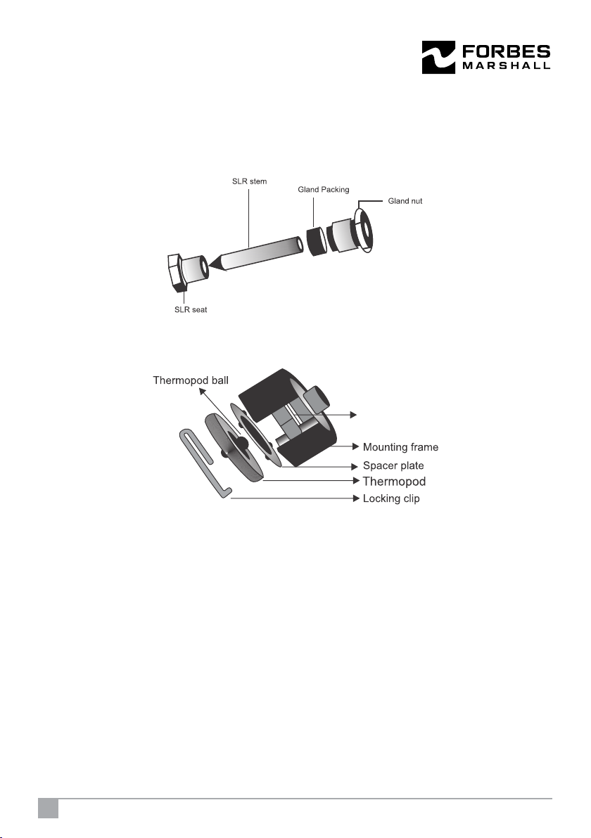
Figure 9: SLR assembly
7.6 Inspection and maintenance of air vent assembly :(Refer to Figure 10)
1. Remove locking clip, thermopod and spacer plate.
2. Fit new gasket between mounting frame and body of the trap. (not visible in the
figure 11), valve seat and mounting frame.
3. Assemble spacer plate, thermopod and fit the locking clip.
7.7 Steam trap testing:
Following methods can be used to determine the operating condition of a trap and
determine if its working properly:
1. Testing traps through visual inspection.
2. Testing traps using temperature gun/equipments.
3. Testing traps using sound/ultrasound
4. Testing traps through online monitoring
7.5 Procedure to fit the steam lock release (SLR) assembly: (Refer to Figure 9)
1. Unscrew the complete SLR assembly.
2. Remove the SLR gasket. (not shown in the figure 9.)
3. Replace the SLR assembly and gasket with new ones.
4. Reset the SLR .
Figure10: Maintaining the air vent assembly
Valve seat
11 Single Orifice Float Trap With SLR and/ or TV

Failure Mode Possible Cause Remedy
Not
discharging at
all.
No condensate is
discharged, and the
surface temperature of
the trap is low.
Check the installation. Check for the flow direction
arrow on the cover casting and the name plate
arrow on the base casting.
Check for blockage in the strainer.
If the actual differential pressure is higher than the
design P, the steam trap would have failed in
closed position as the float buoyancy will not be
adequate to open the valve seat.
Check for the valve and seat assembly for blockage.
Check if the ball float is punctured, if so replace it.
Post replacement, check for water hammering in
process to avoid reoccurrence.
No condensate is
discharged, and the
surface temperature of
the trap is high.
The trap is getting steam locked. Adjust the steam
lock release setting by first closing it fully and then
opening it by 1/4th turn.
Leaking
steam.
Live steam continuously
leaking through the
outlet.
Check the installation. The arrow on the name
plate should point downwards.
Check valve and seat assembly for any deposition
and clean it.
i) Clean and lap the seating area.
ii) Lightly stamp an SS ball on the seating area.
Check for SLR leakage/setting check for air vent
leakage.
Steam leaking from the
trap body.
Tighten the cover nuts and bolts to the
recommended torque.
Check the gasket for any possible damage and
replace it if required.
12
8. Troubleshooting :
If the expected performance is unachievable after the installation of the single orifice float trap,
check the following points for appropriate corrective measures.
SOFT31(DN15-25)

Failure Mode Possible Cause Remedy
Not discharging
enough condensate.
Reduced condensate
carrying capacity of the
trap.
Check parameters and trap sizing. The
trap will not discharge enough
condensate if the actual size is below the
recommended size based on the
condensate load.
Check for back pressure and
corresponding discharge capacities as
per the capacity charts.
i) Replace/repair the leaking and non-
working traps with working traps, the
leak traps may create/increase the
back pressure on the other working
traps connected to the same return
line or,
ii) if there are more than one trap
discharging in a single condensate
return line, then ensure all the traps
have an NRV installed on the outlet of
each trap or,
iii) Ensure all the by-pass valve are closed,
if by-pass valve is leaking or if it is kept
open in closed loop condition which
creates/increases back pressure on the
other working traps, connected to the
same return line.
Flooding of condensate.
Check whether the inlet strainer is
partially blocked.
Check thermostatic valve seat orifice for
blockage. If blocked, clean and lap.
Check main valve seat orifice for
blockage. If blocked, clean and lap.
13 Single Orifice Float Trap With SLR and/ or TV

9. Available Spares: (Refer to Figure 8)
The spare parts available are given in the following table.
13
SOFT31(DN15-25)
ĦÖÓŁŐĻŎ SPARE
TYPE SPARE CONSIST OF SPARE SPECIFICATION SPARE CODE
15/20NB 4.5 BAR(G) SPARE-1520SOFT31-4.5MVKIT
15/20NB 10.0
BAR(G) SPARE-1520SOFT31-10MVKIT
15/20NB 13.0 BAR(G) SPARE-1520SOFT31-13MVKIT
25NB 4.5 BAR(G) SPARE-25SOFT31-4.5MVKIT
25NB 10.0 BAR(G) SPARE-25SOFT31-10MVKIT
25NB 13.0 BAR(G) SPARE-25SOFT31-13MVKIT
1520NB 4.5 BAR(G) SPARE-1520SOFT31-4.5FKIT
15/20NB 10.0 BAR(G) SPARE-1520SOFT31-10FKIT
15/20NB 13.0 BAR(G) SPARE-1520SOFT31-13FKIT
25NB 4.5 BAR(G) SPARE-25SOFT31-4.5FKIT
25NB 10.0 BAR(G) SPARE-25SOFT31-10FKIT
25NB 13.0 BAR(G) SPARE-25SOFT31-13FKIT
AIR VENT
ASSEMBLY
KIT
VALVE SEAT, MOUNTING
FRAME, SPACER PALTE,
THREMOPOD & LOCKING
CLIP
15 / 20 /25 NB SPARE-1550SOFT-AVKIT
COVER/BASE GASKET (
PACK OF 5 NOS. ) 15/20/25NB SPARE-1520SOFT31-GKIT
SCREEN KIT SCREEN ( PACK OF 5 NOS.
) 15 / 20 /25 NB SPARE-152025SOFT31-SKIT
15/20/25NB , TV+SLR
COMBINATION SPARE-152025SOFT31-SLRTVKIT
15/20/25NB , ONLY
SLR COMBINATION SPARE-152025SOFT31-SLRKIT
SOFT31
MAIN
VALVE
ASSEMBLY
KIT
SEAT , GASKET , PIVOT
FRAME , PIN , SCREWS &
FLOAT ASSEMBLY
FLOAT KIT
BALL FLOAT &
COVER/BASE GASKET
(QTY 1 EACH )
GASKET KIT
SLR KIT
SLR SEAT, GLAND
PACKING, SLR STEM &
GLAND NUT
How to Order:
DN 15 Single Orifice Float Trap, SOFT31-T-4.5 bar g, TV, screwed BSPT
How to Order Spares:
Always order spares by using the description given in the column above and stating the size
of the trap.
Example : Main valve assembly for DN 15 Single Orifice Float Trap SOFT31-T-4.5
10. Warranty Period:
As per the ordering information and agreements in the contract.
Forbes Marshall Pvt Ltd
Manufacturing: B-85, Phase II Chakan Indl Area, Sawardari, Chakan
Tal. Khed, Dist, Pune 410 501. Tel: +91(0)2135 393400
Sales: Opp 106th Milestone, Bombay Pune Road, Kasarwadi,
Pune 411034 Tel.: +91 (0)20 39858555
CIN No: U28996PN1985PTC037806
Disclaimer:
This information is strictly proprietary and legally privileged. All contents herein shall be the property of Forbes
Marshall Pvt Ltd and having protection under the intellectual property rights. No part of this information or data may
be distributed or disclosed in any form to any third party. Any dissemination, use, review, distribution, printing or
copying is strictly prohibited, if you are not the intended recipient or user of this information.
Email : [email protected] www.forbesmarshall.com
Doc# FMSS/0417/UM-SOFT31(DN15,20,25)/R1ITEM CODE NO.- 99-001-1018392
This manual suits for next models
1
Table of contents
Other Forbes Marshall Industrial Equipment manuals


