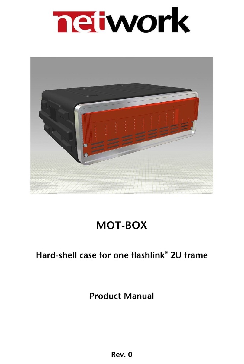
Force Computers MODUSYS 2000 Kernel User manual

-~
ARTISAN
®
~I
TECHNOLOGY
GROUP
Your definitive source
for
quality
pre-owned
equipment.
Artisan Technology
Group
Full-service,
independent
repair
center
with
experienced
engineers
and
technicians
on staff.
We
buy
your
excess,
underutilized,
and
idle
equipment
along
with
credit
for
buybacks
and
trade-ins
.
Custom
engineering
so
your
equipment
works
exactly as
you
specify.
•
Critical
and
expedited
services
•
Leasing
/
Rentals/
Demos
• In
stock/
Ready-to-ship
•
!TAR-certified
secure
asset
solutions
Expert
team
ITrust
guarantee
I
100%
satisfaction
All
tr
ademarks,
br
a
nd
names, a
nd
br
a
nd
s a
pp
earing here
in
are
th
e property of
th
e
ir
r
es
pecti
ve
ow
ner
s.
Find the Emerson / Motorola / Force Computers MODUSYS 2000 at our website: Click HERE

MODUSYS 2000 Kernel
OEM Information for the 2U cPCI Enclosure
P/N 217540 Revision A1
August 2002
DRAFT (EK-A1057-UG Rev A1)

Copyright
The information in this publication is subject to change without notice. Force Computers, GmbH reserves the right to make changes
without notice to this, or any of its products, to improve reliability, performance, or design.
Force Computers, GmbH shall not be liable for technical or editorial errors or omissions contained herein, nor for indirect, special,
incidental, or consequential damages resulting from the furnishing, performance, or use of this material. This information is provided
“as is” and Force Computers, GmbH expressly disclaims any and all warranties, express, implied, statutory, or otherwise, including
without limitation, any express, statutory, or implied warranty of merchantability, fitness for a particular purpose, or non-infringement.
This publication contains information protected by copyright. This publication shall not be reproduced, transmitted, or stored in a
retrieval system, nor its contents used for any purpose, without the prior written consent of Force Computers, GmbH.
Force Computers, GmbH assumes no responsibility for the use of any circuitry other than circuitry that is part of a product of Force
Computers, GmbH. Force Computers, GmbH does not convey to the purchaser of the product described herein any license under the
patent rights of Force Computers, GmbH nor the rights of others.
Copyright•2002 by Force Computers, GmbH. All rights reserved.
The Force logo is a trademark of Force Computers, GmbH.
IEEE is a registered trademark of the Institute for Electrical and Electronics Engineers, Inc.
PICMG, CompactPCI, and the CompactPCI logo are registered trademarks and the PICMG logo is a trademark of the PCI Industrial
Computer Manufacturer’s Group.
MS-DOS, Windows95, Windows98, Windows2000 and Windows NT are registered trademarks and the logos are a trademark of the
Microsoft Corporation.
Intel and Pentium are registered trademarks and the Intel logo is a trademark of the Intel Corporation.
Solaris and Sun are trademarks or registered trademarks of Sun Microsystems, Inc.
Other product names mentioned herein may be trademarks and/or registered trademarks of their respective companies.

World Wide Web: www.forcecomputers.com
24-hour access to on-line manuals, driver updates, and application notes
is provided via SMART, our SolutionsPLUS customer support program
that provides current technical and services information.
Headquarters
Americas Europe Asia
Force Computers Inc.
4305 Cushing Parkway
Fremont, CA 94538
U.S.A.
Tel.: +1 (510) 445-6000
Fax: +1 (510) 445-3382
Force Computers GmbH
Lilienthalstrasse 15
D-85579 Neubiberg/München
Germany
Tel.: +49 (89) 608 14-0
Fax: +49 (89) 609 77 93
Force Computers Japan KK
Shiba Daimon MF Building 4F
2-1-16 Shiba Daimon
Minato-ku, Tokyo 105-0012 Japan
Tel.: +81 (03) 3437 3948
Fax: +81 (03) 3437 3968
Email: smiyagawa@fci.com


ModuSys 2000 Kernel v
Contents
Introduction
The Pre-Configured System ............................................................................. 1-3
Configuration Variants...................................................................................... 1-4
Technical Specifications................................................................................... 1-6
Physical Specifications.....................................................................................................................1-6
Power Input Specification.................................................................................................................1-6
Power Output Specifications............................................................................................................1-7
Acoustic Noise Emission..................................................................................................................1-7
Schallemissionswerte.......................................................................................................................1-8
Acoustical Categories ......................................................................................................................1-8
Acoustical Category Scope..............................................................................................................1-8
Manufacturing space [1]..............................................................................................................1-8
Computer room [2]......................................................................................................................1-8
Open-office/equipment- only space [3].......................................................................................1-9
Open-office/occupied space [4] ..................................................................................................1-9
Private office [5] ..........................................................................................................................1-9
Airflow Specification.......................................................................................................................1-10
Environmental Specifications.........................................................................................................1-11
Warranty and Ordering Information............................................................... 1-13
Returning Products to Force Computers Hardware Maintenance.................................................1-13
Hardware Warranty........................................................................................................................1-13
Availability ......................................................................................................................................1-13
Response Time..............................................................................................................................1-13
Eligible Parts ..................................................................................................................................1-14
Purchaser Responsibility................................................................................................................1-14
Pre-Call Checklist...........................................................................................................................1-14
Return-to-Force Computers Process.............................................................................................1-14
Field Replaceable Parts .................................................................................. 1-16
Setting Up the Module Unit............................................................................. 1-17

vi ModuSys 2000 Kernel
Front and Rear Panel Ports, Connectors and Controls.................................................................1-17
Operator Control Panel Indicators .................................................................................................1-20
Option Support...............................................................................................................................1-21
Choosing a Location for the Module Unit.......................................................................................1-21
Turning On the Module Unit...........................................................................................................1-23
Turning Off the Module Unit...........................................................................................................1-23
Force Computers ModuSys Product Family................................................. 1-24
Backplane
Backplane Block Diagram ................................................................................ 2-3
Connector Locations......................................................................................... 2-4
Connector Summary......................................................................................... 2-5
ModuSys 2735 Connectors............................................................................... 2-6
Positronic Power Connector (A).......................................................................................................2-6
CPCI Connectors (B) (C) (D) (E)......................................................................................................2-7
Connectors B; J1 and J2.............................................................................................................2-7
Connectors B; J3 ........................................................................................................................2-8
Connectors B; J4 ........................................................................................................................2-9
Connectors B; J5 ......................................................................................................................2-10
20-Pin OCP Connector (F).............................................................................................................2-11
20-Pin Server Management Connector (G)...................................................................................2-12
Drive Power Connector (H)............................................................................................................2-13
IDE Data Connector (I)...................................................................................................................2-13
Mains Power Connector (J)............................................................................................................2-14
ICMB Connector (K).......................................................................................................................2-14
Accessing Internal Components
Before You Begin .............................................................................................. 3-3
Preparing to Access Internal Components ......................................................................................3-3
Equipment Requirements.................................................................................................................3-4
Antistatic Precautions.......................................................................................................................3-4
Accessing the Module Unit............................................................................... 3-5
Dismounting a Module Unit from the Rack Frame.......................................... 3-6

ModuSys 2000 Kernel vii
Reassembling the Module Unit in the Rack .................................................... 3-7
Installing and Removing Storage Devices
Drive Bays.......................................................................................................... 4-3
Removing an Internal Disk Drive...................................................................... 4-5
Installing an Internal Disk Drive....................................................................... 4-8
Removing a Drive from the Front Access Drive Bay...................................... 4-9
Installing a Drive into a Front Access Drive Bay.......................................... 4-11
Cable Routing to the Front Access Drive Bay .............................................. 4-12
Installing and Removing Option Boards
Option Board Configurations........................................................................... 5-3
Installing cPCI and PMC Option Boards.......................................................... 5-5
Removing cPCI and PMC Option Boards........................................................ 5-8
Installing an SBC............................................................................................. 5-11
Removing an SBC ........................................................................................... 5-13
Replacing Module Unit Components
Removing the Fan Assembly............................................................................ 6-3
Replacing the Fan Assembly............................................................................ 6-5
Cleaning the Air Filter ....................................................................................... 6-6
Removing the Power Supply Unit .................................................................... 6-8
Replacing the Power Supply Unit .................................................................. 6-10


ModuSys 2000 Kernel ix
Tables
Table 1: Sellable Part Numbers for ModuSys2000..............................................................................1-4
Table 2: Physical Specifications of the ModuSys2000 Enclosure........................................................1-6
Table 3: ModuSys 2000 Power Input Specifications............................................................................1-6
Table 4: ModuSys Power Output Specifications..................................................................................1-7
Table 5: Acoustic Noise Emission Values............................................................................................1-7
Table 6: Schallemissionswerte.............................................................................................................1-8
Table 7: Required Limits for Product Acoustical Noise Emission (Corrected Declared)......................1-9
Table 8: Environmental Specifications for the ModuSys2000 Enclosure...........................................1-11
Table 9: Reliability Estimates for ModuSys 2000 Kernels..................................................................1-12
Table 10: Rear Panel Ports, Connectors and Controls for ModuSys Kernel .......................................1-19
Table 11: Operator Control Panel Indicators........................................................................................1-21
Table 12: Unsuitable Locations for the Module Unit.............................................................................1-22
Table 13: Summary of Connectors on the ModuSys 2735 Backplane...................................................2-5
Table 14: Pin Values for the 20-Pin OCP Connector...........................................................................2-12
Table 15: Pin Values for the 20-Pin OCP Connector...........................................................................2-13
Table 16: Pin Values for the 4-Pin, Drive Power Connector ................................................................2-13
Table 17: Pin Values for the 6-Pin, Backplane Mains Power Connector.............................................2-14
Table 18: Pin Values for the 4-Pin, ICMB Connector...........................................................................2-14
Table 19: Supported Drive Bay Configurations......................................................................................4-3


ModuSys 2000 Kernel xi
Figures
Figure 1: Illustration of the ModuSys 2000............................................................................................1-5
Figure 2: Location of the Front Panel Ports, Connectors, Controls and Indicators.............................1-17
Figure 3: Location of the Rear Panel Ports, Connectors, Controls and Indicators..............................1-18
Figure 4: Location of the Operator Control Panel Indicators...............................................................1-20
Figure 5: Functional Block Diagram of the ModuSys2000 Kernel.........................................................2-3
Figure 6: Connector Layout of the Front of the ModuSys 2735 Backplane...........................................2-4
Figure 7: Connector Layout of the Rear Side of the ModuSys 2735 Backplane...................................2-4
Figure 8: Connector Layout and Pin Values for the Positronic PSU Connectors..................................2-6
Figure 9: Location of SBC CompactPCI Connectors (Top View)..........................................................2-7
Figure 10: B; J3 Connector Pinout.......................................................................................................2-8
Figure 11: B; J4 Connector Pinout.......................................................................................................2-9
Figure 12: B; J5 Connector Pinout, Rows A-C ..................................................................................2-11
Figure 13: B; J5 Connector Pinout, Rows D-E ..................................................................................2-11
Figure 14: Location of Pins on the OCP Connector ..........................................................................2-11
Figure 15: Location of Pins on the OCP Connector ..........................................................................2-12
Figure 16: Main Enclosure Drive Bay..................................................................................................4-3
Figure 17: Optional Front Drive Bay Location......................................................................................4-4
Figure 18: Removing a Disk Drive the Rear Access Drive Bay...........................................................4-6
Figure 19: Rear Access Disk Drive Assembly.....................................................................................4-7
Figure 20: Front Access Drive Bay Assembly. ..................................................................................4-10
Figure 21: Cable Routing over Backplane to Front Access Drive Bay..............................................4-12
Figure 22: SBC Connector Location on the Backplane.......................................................................5-4
Figure 23: Installing an Option Board ..................................................................................................5-6
Figure 24: Installing an RTM Option Board .........................................................................................5-7
Figure 25: Removing an Option Board................................................................................................5-9
Figure 26: Removing an RTM Option Board .....................................................................................5-10
Figure 27: Installing an SBC..............................................................................................................5-12
Figure 28: Removing an SBC............................................................................................................5-14
Figure 29: Removing the Fan Assembly..............................................................................................6-4
Figure 30: Cleaning the Air Filter.........................................................................................................6-7
Figure 31: Removing the Power Supply Unit from the ModuSys Kernel.............................................6-9


ModuSys 2000 Kernel xiii
Using This Manual
This manual introduces the ModuSys 2000 Kernel and describes the Force
Computers ModuSys Product Family 2U enclosure. It contains information
on the product features, using storage devices, installing or removing
option boards and module unit components.
This manual is for authorized personnel, including field service engineers
responsible for building, configuring, and expanding systems created with
ModuSys family of Modular Computing Components. You must be familiar
with computer equipment and components before you use this manual.
You must also be familiar with assembling and disassembling computer
equipment.
Conventions
Convention Description
n.nn A period in numerals signals the decimal point indicator. For
example, 1.75 equals one and three-fourths.
nn nnn A space character separates digits in numerals with 5 or more digits.
For example, 10 000 equals ten thousand.
Italic type Indicates the following:
Complete titles of associated documents and inline electronic
addresses
bold type In procedures, (n) refers to the number in the corresponding figure.
In text, bold type highlights the first occurrence of a term referenced
in the glossary.
Note
A note contains information of special importance to the reader.
C
autio
n
!
A caution contains information to prevent damage to the
equipment.
Danger
A danger contains information to prevent personal injury.
* An asterisk (*) in a part number signifies any number in a particular
position in a part number. For example, EBM3*-PA refers to the part
numbers EBM31-PA, EBM32-PA, EBM33-PA, and so on.

xiv ModuSys 2000 Kernel
How to Get Help
If you need help with the ModuSys Kernel Components, contact one of the
following sources of support:
• Your supplier.
• A Force Computers field applications engineer.
Associated Documentation
The following documentation complements this manual.
• User information manuals accompanying each Single-Board Computer
(SBC). Consult these manuals for more information on the SBC,
firmware, and supported options.
For More Information
If you need help with the ModuSys systems, contact one of the following
sources of support:
• Your supplier
• A Force Computers Field Applications Engineer
• Force ModuSys product family technical support, accessible via email at
• The Force Computers web site at www.forcecomputers.com

ModuSys 2000 Kernel xv
Abbreviations
ModuSys Reference name for the ModuSys kernel plus SBC based system family.
AT Industry standard PC connection.
HDU Hard Disk Unit.
IDE Integrated Device Electronics.
ISA Industry Standard Architecture, an industry standard bus.
ISP In-circuit programmable.
Kernel unit In this manual the term kernel refers to a unit assembled from a backplane
board and an enclosure (which includes the power supply and operator
control panel [OCP]). A kernel does not contain either an SBC or specified
storage devices.
Module unit In this manual the term module unit refers to a module unit assembled
from a backplane board, an enclosure, an SBC and specified storage
devices.
OEM Original Equipment Manufacturer.
OCP Operator Control Panel.
cPCI Compact Peripheral-Component Interface.
PICMG PCI Industrial Computer Manufacturers Group.
RETMA Radio, Electronic and Television Manufacturers Association.
SBC Single Board Computer.
Revision History
SAP No. Revision Date Description Force (Matl) #
217540 A1 Aug 2002 ModuSys 2000 Kernel User Manual EK-A1057-UG


ModuSys 2000 Kernel xvii
!
Safety Notes
The text in this chapter is a translation of the “Sicherheitshinweise” chapter.
This section provides safety precautions to follow when installing,
operating, and maintaining the ModuSys Kernel.
We intend to provide all necessary information to install and handle the
ModuSys Kernel in this manual. However, as the product is complex and its
usage manifold, we do not guarantee that the given information is
complete. If you need additional information, ask your Force Computers
representative.
The ModuSys Kernel has been designed to meet the standard industrial
safety requirements. It must not be used except in its specific area of
office telecommunication industry and industrial control.
Only personnel trained by Force Computers or persons qualified in
electronics or electrical engineering are authorized to install, maintain,
and operate the ModuSys kernel. The information given in this manual is
meant to complete the knowledge of a specialist and must not be taken as
replacement for qualified personnel.
EMC
The system is designed to comply with the limits for a Class B digital
device in this system, pursuant to part 15 of the FCC Rules respectively
EN 55022 Class B. These limits are designed to provide reasonable
protection against harmful interference when the system is operated in a
commercial, business or industrial environment.
The system generates and uses radio frequency energy and, if not
installed properly and used in accordance with this Preliminary System’s
Guide, may cause harmful interference to radio communications.
Operating the system in a residential area is likely to cause harmful
interference, in which case the user will be required to correct the
interference at his own expense. Use of shielded cables when connecting
to the I/O interface ports is required to ensure compliance with EMC
regulations and standards.

xviii ModuSys 2000 Kernel
!
Cabling
Never change the system’s cabling as delivered by Force Computers.
The cabling should follow existing cable paths using existing or similar
cable fastenings. It must not break the airflow through the chassis.
The cabling should comply to the standards used for the existing cabling
wherever applicable.
Check proper function of the system after cabling extensions.
If in doubt concerning cabling, ask your local Force Computers
representative.
VCCI
This is a Class A product based on the standard of the Voluntary Control
Council for Interference by Information Technology Interference (VCCI).
If this equipment is used in a domestic environment, radio disturbance
may arise. When such trouble occurs, the user may be required to take
corrective actions.
Environment
Always dispose of old boards or systems according to your country’s
legislation, if possible in an environmentally acceptable way.
Expansion
To avoid an overload of the system check the total power consumption of
all components, i.e. the installed CPU boards and drives (see the technical
specification of the respective components).
Ensure that any individual output current of any source stays within its
acceptable limits (see the technical specification of the respective source).

ModuSys 2000 Kernel xix
!
Opening
Only personnel trained by Force Computers or qualified persons in
electronics or electrical engineering are authorized to open the system.
To avoid electric shock when opening the chassis it is not sufficient to
switch off the main function switch because it does not remove the AC
line voltage from the system. Therefore, before opening the chassis, an
authorized person must check that the system is powered off and that the
system’s main power connector is disconnected.
Table of contents
