Force Dimension omega haptic device Series User manual
USER MANUAL
omega.x haptic device
version 1.9
Force Dimension
Switzerland
www.forcedimension.com

2

3
summary
The purpose of this document is
>to describe the setup of the omega.x haptic device
>to describe the installation of the software drivers and the Force Dimension SDK
>to describe the operation modes of the omega.x haptic device
glossary
SDK refers to the Software Development Kit (SDK) for all Force Dimension products.
omega.x refers to the base haptic device shared by the omega.3, omega.6 and omega.7 hap-
tic devices. Unless specified, all instructions in this manual apply to all three device
types.

4

5
table of contents
1. system overview 7
2. important safety instructions 8
3. setting up the omega.x haptic device 9
3.1 unpacking the device 9
3.2 installing the power supply 10
4. configuring the omega.x under Windows 11
4.1 installation description 11
4.2 installing the drivers 11
5. configuring the omega.x under Linux 12
5.1 installing the software 12
5.2 installation description 12
5.3 installing the drivers 12
6. configuring the omega.x under macOS 13
6.1 installing the software 13
6.2 installation description 13
6.3 installing the drivers 13
7. operating the omega.x 14
7.1 coordinate system 14
7.2 operating modes 16
7.3 running the Haptic Desk program 18
7.4 running the demonstrations programs 19
8. technical information - omega.3 21
9. technical information - omega.6 23
10. technical information - omega.7 25

6
7
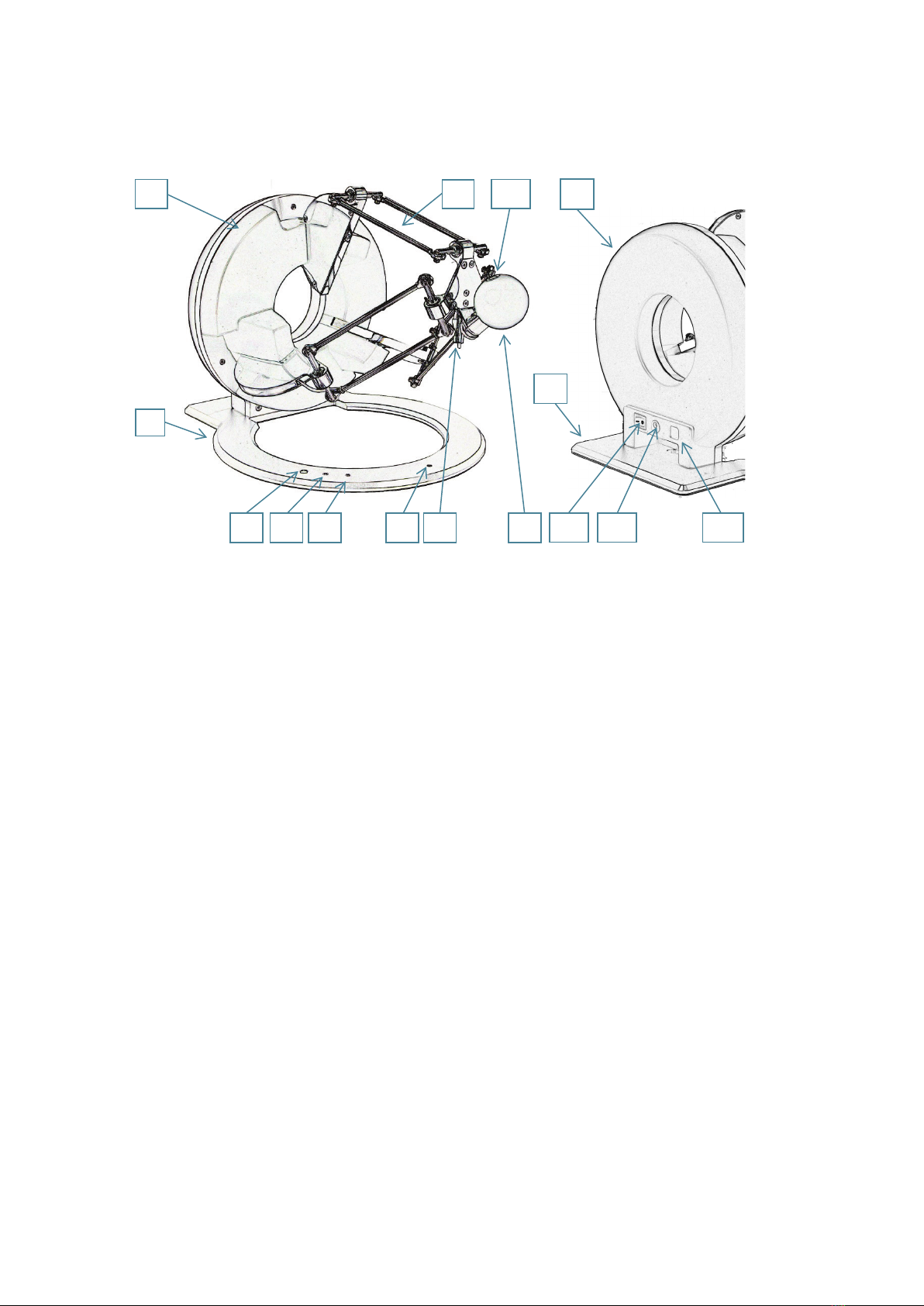
1. system overview
figure 1 – overview of the omega.3 haptic device
1. base plate
2. control unit
3. front arms
4. end-effector
5. force button
6. calibration pole
7. calibration pit
8. status LED
9. force LED
10. user button
11. power switch
12. power connector
13. USB connector
2 3
1
5 9 8
2
1
11
12
13
10
6 4
7

8
2. important safety instructions
IMPORTANT
WHEN USING THIS HAPTIC DEVICE, BASIC SAFETY PRECAUTIONS
SHOULD ALWAYS BE FOLLOWED TO REDUCE THE RISK
OF FIRE, ELECTRICAL SHOCK, OR PERSONAL INJURY.
1. read and understand all instructions
2. follow all warnings and instructions marked on your haptic device
3. do not use or place your haptic device near water
4. place your haptic device securely on a stable surface
5. make sure that the workspace of your haptic device is free of objects
6. do not overload wall outlets and extension cords as this can result in a risk of fire or electri-
cal shock
7. switch off your haptic device when it is not in use
8. to reduce the risk of electrical shock, do not disassemble your haptic device

9
3. setting up the omega.x haptic device
This section describes the different steps to follow to safely setup your omega.x haptic device
before use.
IMPORTANT
PLEASE KEEP THE ORIGINAL PACKAGING
ONLY USE THE ORIGINAL PACKAGING DURING STORING OR SHIPPING
3.1 unpacking the device
Before unpacking the omega.x haptic device, remove the haptic device foam stabilizer and the
accessories foam section located inside the shipping box.
figure 2 – view when opening the shipping box
haptic device
foam stabilizer
haptic device
accessories

10
Carefully remove the haptic device and the foam stabilizer from the box, then remove the foam
stabilizer from the haptic device.
figure 3 – view of the shipping box after removal of the foam stabilizer and accessories
The accessories compartment contains the power supply, power and USB cables, as well as the
USB flash drive.
figure 4 – omega.x accessories
3.2 installing the power supply
Plug the power supply into the power connector. For safety purposes you should only operate your
omega.x haptic device using the original Force Dimension power supply that came with your hap-
tic device controller. Replacement power supplies can be ordered directly from Force Dimension.
end-effector
foam stabilizer
haptic device
power supply
USB flash drive
USB cable
power cable

11
4. configuring the omega.x under Windows
The USB driver must be first installed onto your system prior to connecting the omega.x to the
computer. To do this, perform the following steps:
1. plug the Force Dimension USB flash drive into your Windows computer
2. open the \Windows folder on the USB flash drive and select the appropriate \32-bit or \64-
bit subfolder according to the operating system version on your computer
3. run the installation program and follow its instructions
4.1 installation description
The installation program creates the following subfolders in:
C:\Program Files\Force Dimension\sdk-<version>
\bin subfolder
This directory contains the demonstration executables and the DLL files required to run the
omega.x software. The required DLL files are also copied to the Windows system folder during the
installation.
\drivers subfolder
This directory contains the USB drivers required to operate your haptic device.
\examples subfolder
This directory contains the demonstration programs. Example applications described in section
7.4 and come with their full source code.
\doc subfolder
All documentation files and notices are located in that directory.
\manuals subfolder
All hardware user manuals are located in that directory.
\lib,\include subfolders
These directories contain the files required to compile your application with the Force Dimension
SDK. Please refer to the on-line programming manual for more information.
4.2 installing the drivers
USB drivers
The omega.x requires the Force Dimension USB driver. These drivers are installed automatically,
and no additional step is required.

12
5. configuring the omega.x under Linux
5.1 installing the software
The Force Dimension development folder must be installed onto your system before the omega.x
can be used. To do this, perform the following steps:
1. plug the Force Dimension USB flash drive into your Linux computer
2. extract the sdk-<version>.tar.gz archive for your system architecture from the \Linux
subfolder to the desired location (typically your home folder) by running the following com-
mand within the target folder:
tar –zxvf sdk-<version>.tar.gz
3. this will create a sdk-<version> development folder in the target location
5.2 installation description
The development folder contains the following directories:
\bin subfolder
This directory contains the demonstration executables and the binary files required to run the
omega.x software.
\examples subfolder
This directory contains the demonstration programs. Example applications described in section
7.4 and come with their full source code.
\doc subfolder
All documentation files and notices are located in this subfolder.
\manuals subfolder
All hardware user manuals are located in that directory.
\lib,\include subfolders
These directories contain the files required to compile your application with the Force Dimension
SDK. Please refer to the on-line programming manual for more information.
5.3 installing the drivers
The Linux version of the Force Dimension SDK requires the development packages for the
libusb-1.0 to be installed on your Linux distribution.
IMPORTANT
PLEASE NOTE THAT USB ACCESS TO THE HAPTIC DEVICE REQUIRES SUPERUSER
PRIVILEDGES ON MOST LINUX DISTRIBUTIONS

13
6. configuring the omega.x under macOS
6.1 installing the software
The Force Dimension development folder must be installed onto your system before the omega.x
can be used. To do this, perform the following steps:
1. plug the Force Dimension USB flash drive into your Apple computer
2. open the sdk-<version>.dmg file for your version of macOS from the \macOS folder and
extract the sdk-<version> folder to the desired location (typically your home folder)
3. this will create a sdk-<version> development folder in the target location
6.2 installation description
The development folder contains the following directories:
\bin subfolder
This directory contains the demonstration executables and the binary files required to run the
omega.x software.
\examples subfolder
This directory contains the demonstration programs. Example applications described in section
7.4 and come with their full source code.
\doc subfolder
All documentation files and notices are located in this subfolder.
\manuals subfolder
All hardware user manuals are located in that directory.
\lib,\include subfolders
These directories contain the files required to compile your application with the Force Dimension
SDK. Please refer to the online programming manual for more information.
6.3 installing the drivers
The macOS version of the Force Dimension SDK uses Apple’s native USB drivers. No further instal-
lation is required.

14
7. operating the omega.x
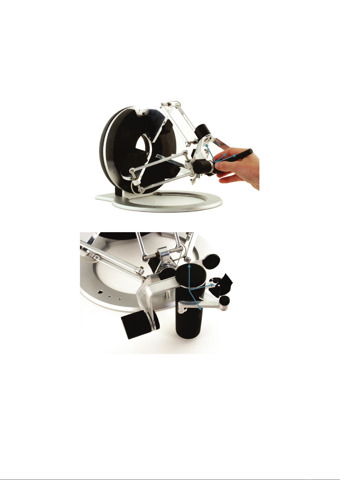
7.1 coordinate system
base translation
The position of the center of the end-effector (handle) is expressed in Cartesian coordinate and in
IUS (metric) unit. Figure 5 illustrates the coordinate system.
The actual origin of the coordinate system (0,0,0) is located on a virtual point situated at the cen-
ter of the physical workspace of the haptic device.
figure 5 – Cartesian coordinate system of the omega.x haptic device
X-axis
Y-axis
Z-axis
15
wrist orientation
The omega.6 and omega.7 haptic devices incorporate a rotational wrist. The orientation of the
wrist is expressed by a reference frame Rwrist which is numerically represented using a 3x3 rotation
matrix. This reference frame is expressed in relation to the world coordinate system described in
figure 5 and is computed from the angle values returned by the joint sensors mounted of each
revolute axis of the wrist.
figure 6 – reference frame of the wrist (omega.6 and omega.7 haptic devices)
gripper angle
The angular position of the force gripper is returned in either degrees or radian.
A positive angle value is returned for right-hand omega.7 haptic devices. A negative angle value
is returned for left-hand haptic devices.
Angular values closer to zero correspond to configurations where the force gripper is in a closed
configuration. Opening of the force gripper increases the magnitude of the angle.
X-axis
Y-axis
Z-axis
Z-axis
Y-axis
X-axis

16
7.2 operating modes
status indicators
The displays the status of the system:
>LED OFF the system is off
>LED ON the system is ready
>LED FLASHING (fast) the system requires calibration
>LED FLASHING (slow) the wrist requires manual calibration (omega.6 or omega.7)
While the status LED is ON, it is possible to read the position of the of the end-effector, but no
forces can be applied. Forces must be enabled by pressing the force button. When the forces are
enabled, the force LED is turned ON. Forces can be disabled by pressing force button again.
features
calibration
Calibration is necessary to obtain accurate, reproducible localization of the end-effector within
the workspace of the device. The omega.x is designed in such a way that there can be no drift of
the calibration over time, so the procedure only needs to be performed once when the device is
powered ON.
The calibration procedure consists in placing calibration pole in the dedicated calibration pit. The
device detects when the calibration position is reached and the status LED stops flashing.
Figure 7 illustrates the calibration procedure. After the initial calibration described above, the LED
will stop flashing (omega.3).
figure 7 – calibration procedure
On the omega.6 and omega.7, the status LED will blink at a slower frequency, indicating that the
wrist is usable but not fully calibrated. To fully calibrate the omega.6 and omega.7 wrists, each of
the three rotation axes of the wrist and the grasping axis of the omega.7 must be moved by hand
to their respective end-stops positions. When the device has reached all end-stops, the LED stops
flashing, and the device is now fully calibrated.
Alternatively, an automatic calibration procedure of the omega.x active axes can be performed by
software using the Force Dimension SDK, for example by launching the application HapticInit
which automatically drives the device throughout its workspace. Please do not touch the device
during this automatic calibration procedure. After calibration, the device is ready for normal op-
eration.

17
gravity compensation
To prevent user fatigue and to improve dexterity during manipulation, the omega.x features gravity
compensation. When gravity compensation is enabled, the weights of the arms and of the end-
effector are taken into account and a vertical force is dynamically applied to the end-effector in
addition to the desired user force command. Please note that gravity compensation is computed
on the host computer, and therefore only gets updated every time a new force command is sent to
the haptic device by the application. Gravity compensation is enabled by default and can be dis-
abled through the Force Dimension SDK.
forces
By default, and when an application opens a connection to the device, the forces are disabled.
Forces can be enabled or disabled at any time by pressing the force button.
brakes
The device features electromagnetic brakes that can be enabled through the Force Dimension
SDK. These brakes are enabled by default every time the forces are disabled. When the brakes are
engaged, a viscous force is created that prevents rapid movement of the end-effector.
safety features
The omega.x features several safety features designed to prevent uncontrolled application of
forces and possible damage to the device. These safety features can be adjusted or disabled via
a protected command in the Force Dimension SDK.
IMPORTANT
PLEASE NOTE THAT THE WARRANTY MAY NOT APPLY
IF THE SAFETY FEATURES HAVE BEEN OVERRIDEN.
When a connection to the omega.x haptic device is made from the computer, the forces are auto-
matically disabled to avoid unexpected behaviors. The user must press the force button to enable
the forces. This feature can be bypassed through the Force Dimension SDK.
If the control unit detects that the velocity of the end-effector is higher than the programmed se-
curity limit, the forces are automatically disabled, and the device brakes are engaged to prevent
a possibly dangerous acceleration from the device. This velocity threshold can be adjusted or re-
moved through the Force Dimension SDK.
Please refer to the on-line programming manual for more information.

18
7.3 running the Haptic Desk program
The Haptic Desk application is available as a test and diagnostic program and offers the following
capabilities:
>list all Force Dimension haptic devices connected to the system
>test the position reading of the haptic device in Cartesian coordinates
>test all force and torque capabilities of the haptic device
>run the auto-calibration procedure
>read the haptic device status
>read the haptic device encoder sensors individually
>read the haptic device user button (if available)
figure 8 – Haptic Desk test and diagnostic program

19
7.4 running the demonstrations programs
Two demonstration programs can also be used to diagnose the device. The source code and an
executable file for each of these demonstration programs are provided in two separate directories
named \gravity and \torus.
Once the system is setup, we suggest running application gravity to check that everything is
working properly and to evaluate your system's performance independently of the graphics ren-
dering performance. Application torus will allow you to test the combined performance of hap-
tics and graphics rendering.
gravity example
This example program runs a best effort haptic loop to compensate for gravity. The appropriate
forces are applied at any point in space to balance the device end-effector so that it is safe to let
go of it. The refresh rate of the haptic loop is displayed in the console every second.
figure 9 – gravity example

20
torus example
The torus example displays an OpenGL scene with haptic feedback.
figure 10 – torus example
note – OpenGL must be installed for your compiler and development environment to compile this
example. Please refer to your compiler documentation for more information, or consult
http://www.opengl.org
Table of contents
Other Force Dimension Medical Equipment manuals


Popular Medical Equipment manuals by other brands


Trudell Medical International
Trudell Medical International AeroChamber Plus Z STAT quick start guide

Belmont Medical Technologies
Belmont Medical Technologies HYPERTHERMIA PUMP Quick reference guide

DeVilbiss Healthcare
DeVilbiss Healthcare drive SUVA Instructions for use

GE
GE MAC 5000 Service manual

IMP
IMP De Mayo D2 Knee Positioner Instructions for use

Gate
Gate Bure Rise & Go DB 56-309 Instructions for use