Force Dimension sigma.7 haptic device User manual
USER MANUAL
sigma.7 haptic device
version 1.2
06.2013
Force Dimension
Route de Saint-Cergue 295
CH – 1260 Nyon
Switzerland
www.forcedimension.com

2

3
summary
The purpose of this document is
>to describe the setup of the sigma.7 haptic device
>to describe the installation of the drivers and haptic software API
>to describe the operation of the sigma.7 haptic device
glossary
FD-SDK refers to the Software Development Kit (SDK) for all Force Dimension products.
sigma.x refers to the base haptic device shared by sigma.7 haptic devices. Unless speci-
fied, all instructions in this manual apply to all sigma device types.

4

5
table of contents
1.device description 6
2.important safety instructions 7
3.setting up the sigma.7 8
3.1device installation 8
3.2installing the power supply 12
4.configuring the sigma.7 under Windows 13
4.1installing the software 13
4.2installation description 13
4.3installing the drivers 13
5.configuring the sigma.7 under Linux 14
5.1installing the software 14
5.2installation description 14
5.3installing the drivers 14
6.configuring the sigma.7 under Mac OS X 15
6.1installing the software 15
6.2installation description 15
6.3installing the drivers 15
7.using the sigma.7 16
7.1device geometry 16
7.2operating the sigma.7 17
7.3running the Haptic Desk program 18
7.4running the demonstrations programs 19
8.technical information 23

1. device description
6
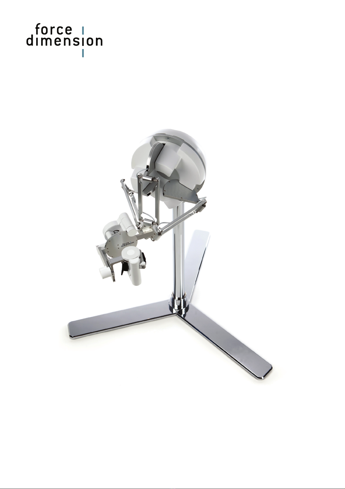
11
4 9
6 5
12
8
10
7 3 2
1
figure 1 – sigma.7 haptic device overview
1. device stand rear leg 7. end-effector (grasping handle)
2. device stand front legs 8. pole mounting interface
3. device stand pole 9. power switch
4. device main body 10. power connector
5. arms of translational base 11. USB connector
6. rotational wrist 12. user I/O connector

2. important safety instructions
IMPORTANT
WHEN USING THIS UNIT, BASIC SAFETY PRECAUTIONS
SHOULD ALWAYS BE FOLLOWED TO REDUCE THE RISK
OF FIRE, ELECTRICAL SHOCK, OR PERSONAL INJURY.
1. read and understand all instructions
2. follow all warnings and instructions marked on this unit
3. do not use or place this system near water
4. place the unit securely on a stable surface
5. make sure that the workspace of the sigma.7 is free of objects
6. do not overload wall outlets and extension cords
this can result in a risk of fire or electrical shock
7. switch off the sigma.7 when it is not in use
8. to reduce the risk of electrical shock, do not disassemble the sigma.7
7

3. setting up the sigma.7
This section describes the steps to follow to setup your sigma.7 device before use.
IMPORTANT
PLEASE KEEP THE ORIGINAL PACKAGING
ONLY USE THE ORIGINAL PACKAGING FOR STORING OR SHIPPING
3.1 device installation
The sigma.7 haptic device is shipped in 3 boxes. Please start by opening the 2 smaller boxes
which contain the device stand. The operations described below are best performed by a team of
2 people.
9 screws and a corresponding orange hex-driver tool are provided in the packaging.
Each one of the 3 legs is mounted on the pole by securely fastening 3 screws, as shown in figure
2. Make sure that the legs are laid out as shown in figure 3, so that the rubber feet of the lower 2
legs on this figure are located near the lower leg borders. The rear leg of the stand is recognized
with the rubber foot being located at its centered position.
figure 2 – mounting of the device stand legs onto the pole
8

figure 3 – mounted stand legs showing correct layout of the 3 rubber feet (yellow arrows)
rear leg
Once the device stand mounted, you may open the larger hard plastic container housing the
sigma.7 haptic device base.
First release the cables from the front packaging foam block before removing the system from
the box, as shown in figure 4.
figure 4 – box containing sigma.7 device, after removal of front foam part
Remove the pole attachment interface and power supply before lifting out device from its lower
foam block as illustrated in figure 5. While a first person may hold the device, a second person
may remove the lower foam block and place it on a table top or any other stable flat surface. The
device can then be installed back on this lower foam block, in its initial position, as shown in
figure 6.
pole interface
9

figure 5 – the device is lifted out of the plastic container
figure 6 – the device is placed back on its lower foam block
Insert the pole attachment interface at the back of device body shroud and securely fasten the
screw by using the provided red hex-driver tool, as illustrated in figure 7. Please make sure that
the pole attachment interface is correctly oriented as shown in figure 8. By using the same hex-
driver you may now loosen the clamping screw.
figure 7 – mounting of the pole attachment interface
10

Finally the sigma.7 device base can be mounted on its stand pole by sliding it from the top, as
illustrated in figure 8. Place the base at the desired height and lock the mechanism by fastening
the clamping screw as shown in figure 9.
Please verify that the device is correctly secured by making sure that the device base cannot ro-
tate around its vertical pole. If any slippage occurs, further tightening may be necessary.
figure 8 – after loosening clamping screw, device body is mounted on stand pole
clamping screw
figure 9 –fastening of clamp screw while holding the device with the other hand
Your sigma.7 haptic device is now fully assembled. You may now place the haptic device at your
console desk where you will be operating the system. Please note that optimal wrist dexterity is
achieved when the forearm of the operator is aligned with the first rotational motion axis of the
wrist mechanism, as shown in figure 10 (yellow dashed lines). This optimal configuration can be
obtained by correctly positioning and orientating the device with respect to the operator.
For optimal stability, the rear stand leg (see figure 3) should be aligned with the pole attachment
interface protruding from the back of device body, as shown in figure 10 (blue dashed lines).
11
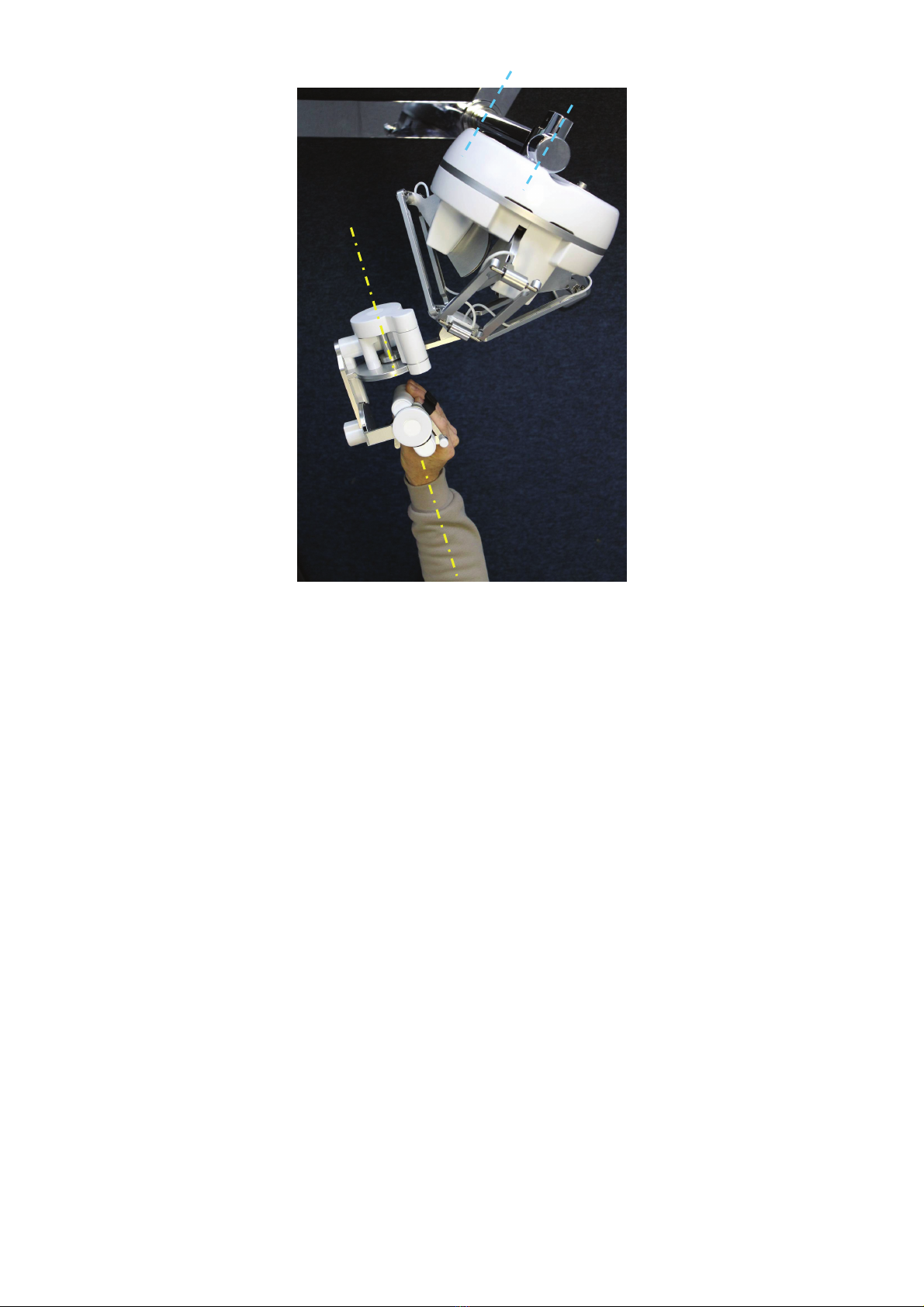
figure 10 – relative forearm alignment for optimal wrist dexterity (yellow dashed lines) and rear leg orienta-
tion of stand (blue dashed lines)
You will also find in the plastic container the power and USB cables, as well as the driver and
SDK installation media (memory stick).
3.2 installing the power supply
Plug the power supply into the power connector. The system may support either high-input volt-
age (200-240 volt) or low-input voltage (100-120 volt). For safety purposes you should only op-
erate your sigma.7 haptic device using the original Force Dimension power supply that came
with your device. Replacement power supplies can be ordered directly from Force Dimension.
12

4. configuring the sigma.7 under Windows
4.1 installing the software
The installation USB drive must be installed onto your system before connecting the sigma.7 to
the system. To do this, perform the following steps.
1. plug the Force Dimension USB drive into your system
2. open the \Windows subfolder on the USB drive
3. run setup.exe icon to launch the installation program
4. follow the instructions given by the installation program
4.2 installation description
The installation program creates the following subfolders in :
C:\Program Files\Force Dimension\sdk-<version>
\bin subfolder
This directory contains the demonstration executables and the DLL files required to run the sig-
ma.7 software. The required DLL files are also copied to the Windows system folder during the
installation.
\drivers subfolder
This directory contains the USB and PCI drivers required to operate your device.
\examples subfolder
This directory contains the demonstration programs. Example applications described in section
7.4 and come with their full source code.
\doc subfolder
All documentation files and notices are located in that directory.
\manuals subfolder
All hardware user manuals are located in that directory.
\lib,\include subfolders
These directories contain the files required to compile you application with the Force Dimension
SDK. Please refer to the on-line programming manual for more information.
4.3 installing the drivers
USB drivers
The sigma.7 requires the Force Dimension USB driver. These drivers are installed automatically
and no additional step is required.
13

5. configuring the sigma.7 under Linux
5.1 installing the software
The Force Dimension development folder must be installed onto your system before the sigma.7
can be used. To do this, perform the following steps:
5. plug the Force Dimension USB drive into your system
6. decompress the sdk-<version>.tar.gz file from the drive \Linux subfolder to the de-
sired location (typically your home folder) by running the following command within the tar-
get folder:
tar –zxvf sdk-<version>.tar.gz
7. this will create a sdk-<version> development folder in the target location
5.2 installation description
The development folder contains the following directories:
\bin subfolder
This directory contains the demonstration executables and the binary files required to run the
sigma.7 software.
\examples subfolder
This directory contains the demonstration programs. Example applications described in section
7.4 and come with their full source code.
\doc subfolder
All documentation files and notices are located in this subfolder.
\manuals subfolder
All hardware user manuals are located in that directory.
\lib,\include subfolders
These directories contain the files required to compile you application with the Force Dimension
SDK. Please refer to the on-line programming manual for more information.
5.3 installing the drivers
The Linux version of the Force Dimension SDK requires the development packages for the li-
busb-1.0 and freeglut to be installed on your Linux distribution.
14

6. configuring the sigma.7 under Mac OS X
6.1 installing the software
The Force Dimension development folder must be installed onto your system before the sigma.7
can be used. To do this, perform the following steps:
8. plug the Force Dimension USB drive into your system
9. open the sdk-<version>.dmg file from the drive \Mac OS subfolder and extract the sdk-
<version> folder to the desired location (typically your home folder)
10. this will create a sdk-<version> development folder in the target location
6.2 installation description
The development folder contains the following directories:
\bin subfolder
This directory contains the demonstration executables and the binary files required to run the
sigma.7 software.
\examples subfolder
This directory contains the demonstration programs. Example applications described in section
7.4 and come with their full source code.
\doc subfolder
All documentation files and notices are located in this subfolder.
\manuals subfolder
All hardware user manuals are located in that directory.
\lib,\include subfolders
These directories contain the files required to compile you application with the Force Dimension
SDK. Please refer to the on-line programming manual for more information.
6.3 installing the drivers
The Apple version of the Force Dimension SDK uses Apple’s native USB drivers, which are in-
cluded in Mac OS X 10.4 and higher. No further installation is required.
15

7. using the sigma.7
7.1 device geometry
sigma.7 translation axis
The position of the center of the end-effector (handle) can be read from the controller. The sys-
tem converts the encoder values into (X, Y, Z) coordinates, expressed in IUS (metric) unit. Figure
11 shows the coordinate system. The actual origin of the coordinate system (0,0,0) is located on
a virtual point at the center of the workspace.
Y
X
Z
figure 11 – coordinate system
16

7.2 operating the sigma.7
features
calibration –calibration is necessary to obtain accurate, reproducible localization of the end-
effector within the workspace of the device. The sigma.7 is designed in such a way that there
can be no drift of the calibration over time, so the procedure only needs to be performed once
when the device is powered on.
The automatic calibration procedure is performed by software using the DHD-API, for example by
launching the application "autoinit.exe" which automatically drives the device throughout its
workspace: Please do not touch the device during this automatic calibration procedure. After
calibration, the device is ready for normal operation.
gravity compensation – to prevent user fatigue and to increase accuracy during manipulation,
the sigma.7 features gravity compensation. When gravity compensation is enabled, the weights
of the arms and of the end-effector are taken into account and a vertical force is dynamically ap-
plied to the end-effector on top of the user command. Please note that gravity compensation is
computed on the host computer, and therefore it only gets updated whenever a force command
is sent to the device by the application. Gravity compensation is enabled by default and can be
disabled via the Force Dimension SDK.
forces - by default, when an application opens a connection to the device, the forces are dis-
abled. Forces can be enabled or disabled via software.
brakes – the device features electromagnetic brakes that can be enabled via the DHD-API. The
brakes are on by default when the forces are disabled, and can be enabled automatically by the
control unit in some cases. When the brakes are on, a viscous force is created that prevents rap-
id movement of the end-effector.
safety features
The sigma.7 features several safety features designed to prevent uncontrolled application of
forces and possible damage to the device. These safety features can be adjusted or disabled via
a protected command in the Force Dimension SDK.
IMPORTANT
PLEASE NOTE THAT THE WARRANTY MAY NOT APPLY
IF THE SAFETY FEATURES HAVE BEEN OVERRIDEN.
When a connection to the device is made from the computer, the forces are automatically dis-
abled to avoid unexpected behaviors.
If the control unit detects that the velocity of the end-effector is higher than the programmed
security limit, the forces are automatically disabled and the device brakes are engaged to pre-
vent a possibly dangerous acceleration from the device. This velocity threshold can be adjusted
or removed via the Force Dimension SDK. Please refer to the on-line programming manual for
more information.
17

7.3 running the Haptic Desk program
Under Windows, the Haptic Desk is available as a test and diagnostic program.
Haptic Desk allows the programmer to:
>list all Force Dimension haptic devices connected to the system
>test each device position reading
>test each device force/torque capability
>test each device auto-calibration procedure
>read each device status
>read any device encoder individually
figure 5 – Haptic Desk test and diagnostic program
18

7.4 running the demonstrations programs
Two demonstration programs can also be used to diagnose the device. The source code and an
executable file for each of the demonstration programs are provided in two separate directories
named \gravity and \torus.
Once the system is setup, we suggest running gravity to check that every thing is working
properly and to evaluate your system's performance independently of the graphics rendering
performance. torus will allow you to test the combined performance of haptics and graphics
rendering.
gravity example
This example program runs a best effort haptic loop to compensate for gravity. The appropriate
forces are applied at any point in space to balance the device end-effector so that it is safe to let
go of it. The refresh rate of the haptic loop is displayed in the console every second.
figure 6 – gravity example
19

torus example
The torus example displays an OpenGL scene that can be haptically explored.
figure 7 – reflections example
note – OpenGL and the OpenGL Utility Toolkit (GLUT) must be installed for your compiler and
development environment to compile this example. Please refer to your compiler documentation
for more information, or consult http://www.opengl.org/resources/libraries/glut.html
20
Other manuals for sigma.7 haptic device
1
Table of contents
Other Force Dimension Medical Equipment manuals


Popular Medical Equipment manuals by other brands


Otto Bock
Otto Bock 1C63 Triton Low Profile Instructions for use

Top shelf Orthopedics
Top shelf Orthopedics ProtectOR Instructions for use

FujiFilm
FujiFilm SONOSITE X-PORTE user guide

Ferno
Ferno AS-190 user manual

TelePatch
TelePatch PM750 user manual

Handicare
Handicare LinidoSolutions LI2403.150 Series manual