ForeScout CounterACT User manual

Forescout
Quick Installation Guide
Single Appliance
Version 8.1

Quick Installation Guide Single Appliance
Version 8.1 2
Contact Information
Forescout Technologies, Inc.
190 West Tasman Drive
San Jose, CA 95134 USA
https://www.forescout.com/support/
Toll-Free (US): 1.866.377.8771
Tel (Intl): 1.408.213.3191
Support: 1.708.237.6591
About the Documentation
Refer to the Resources page on the Forescout website for additional technical
documentation: https://www.forescout.com/company/resources/
Have feedback or questions? Write to us at documentation@forescout.com
Legal Notice
© 2019 Forescout Technologies, Inc. All rights reserved. Forescout Technologies, Inc. is a
Delaware corporation. A list of our trademarks and patents can be found at
https://www.forescout.com/company/legal/intellectual-property-patents-trademarks. Other
brands, products, or service names may be trademarks or service marks of their respective
owners.
2019-03-18 14:40

Quick Installation Guide Single Appliance
Version 8.1 3
Table of Contents
Welcome to Version 8.1 ............................................................................... 5
Forescout Package Contents ..........................................................................5
Overview...................................................................................................... 6
1. Create a Deployment Plan ........................................................................ 6
Decide Where to Deploy the Appliance............................................................6
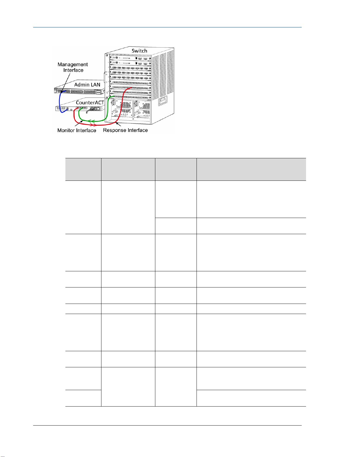
Appliance Interface Connections.....................................................................6
Management Interface..............................................................................6
Monitor Interface......................................................................................9
Response Interface...................................................................................9
2. Set up your Switch ................................................................................. 11
A. Switch Connection Options ......................................................................11
1 Standard Deployment (Separate Management, Monitor and Response
Interfaces) ............................................................................................11
2 Passive Inline Tap................................................................................11
3 Active (Injection-Capable) Inline Tap .....................................................11
4 IP Layer Response (for Layer-3 Switch Installations)................................11
B. Switch Setting Notes...............................................................................12
VLAN (802.1Q) Tags...............................................................................12
Additional Guidelines ..............................................................................12
3. Connect Network Cables and Power On.................................................. 13
A. Unpack the Appliance and Connect Cables.................................................13
B. Record the Interface Assignments ............................................................13
C. Power on the Appliance...........................................................................14
4. Configure the Appliance ......................................................................... 15
5. Remote Management.............................................................................. 19
iDRAC Setup..............................................................................................19
Enable and Configure the iDRAC Module....................................................19
Connect the Module to the Network ..........................................................21
Login to iDRAC.......................................................................................21
6. Verify Connectivity................................................................................. 23
Verify the Management Interface Connection.................................................23
Perform a Ping Test ....................................................................................23
7. Set Up the Forescout Console................................................................. 24
Install the Console......................................................................................24
Log In.......................................................................................................24
Perform Initial Setup ..................................................................................25
Before You Start the Initial Setup.............................................................26

Quick Installation Guide Single Appliance
Version 8.1 4
Additional Forescout Documentation.......................................................... 27
Documentation Downloads ......................................................................27
Documentation Portal .............................................................................28
Forescout Help Tools...............................................................................28

Quick Installation Guide Single Appliance
Version 8.1 5
Welcome to Version 8.1
The Forescout platform provides infrastructure and device visibility, policy
management, orchestration and workflow streamlining to enhance network security.
The platform provides enterprises with real-time contextual information of devices
and users on the network. Policies are defined using this contextual information that
helps ensure compliance, remediation, appropriate network access and streamlining
of service operations.
This guide describes the
installation for a single
stand-alone CounterACT
Appliance preinstalled
with version 8.0. Some
Appliances may come
preinstalled with a later version. To use version 8.1, follow the approved
upgrade path, outlined in the version Release Notes.
For more detailed information or information about upgrade or about deploying
multiple Appliances for enterprise-wide network protection, refer to the Forescout
Installation Guide and Forescout Administration Guide. See Additional Forescout
Documentation for information on how to access these guides.
Additionally, you can navigate to the support website located at:
http://www.forescout.com/support for the latest documentation, knowledge base
articles, and updates for your Appliance.
Forescout Package Contents
Your Forescout package includes the following components:
The CounterACT Appliance
Front Bezel
Rail Kits (Mounting brackets)
Power cord(s)
DB9 Console connecting cable (for serial connections only)
Enterprise Products Safety, Environmental, and Regulatory Information
Getting Started document (CT-xxxx Appliances based on hardware revision 5x
and Forescout 51xx Appliances only)

Quick Installation Guide Single Appliance
Version 8.1 6
Overview
Perform the following to set up your Forescout deployment:
1. Create a Deployment Plan
2. Set up your Switch
3. Connect Network Cables and Power On
4. Configure the Appliance
5. Remote Management
6. Verify Connectivity
7. Set Up the Forescout Console
1. Create a Deployment Plan
Before performing the installation, you should decide where to deploy the Appliance
and learn about Appliance interface connections.
Decide Where to Deploy the Appliance
Selecting the correct network location where the Appliance will be installed is crucial
for a successful deployment and optimal performance. The correct location will
depend on your desired implementation goals and network access policy. The
Appliance should be able to monitor the traffic that is relevant to the desired policy.
For example, if your policy depends on monitoring authorization events from
endpoints to corporate authentication servers, the Appliance will need to be installed
so that it sees endpoint traffic flowing into authentication server(s).
For more information about installation and deployment, refer to the Forescout
Installation Guide. See Additional Forescout Documentation for information on how
to access this guide.
Appliance Interface Connections
The Appliance is generally configured with three connections to the network switch.
Management Interface
The management interface allows you to manage the Forescout platform and
perform queries and deep inspection of endpoints. The interface must be connected
to a switch port with access to all network endpoints.
Each Appliance requires a single management connection to the network. This
connection requires an IP address on the local LAN and port 13000/TCP access from
machines that will be running the Console management application. The
management port must have access to additional network services.

Quick Installation Guide Single Appliance
Version 8.1 7
Network Access Requirements
Port Service To or From
Forescout
Platform
Function
22/TCP
SSH
From Allows remote inspection of OS X and
Linux endpoints.
Allows the Forescout platform to
communicate with network switches
and routers.
To Allows access to the Forescout
platform command line interface.
2222/TCP SSH To (High Availability) Allows access to the
physical Appliances that are part of the
High Availability pair.
Use 22/TCP to access the shared
(virtual) IP address of the pair.
25/TCP SMTP From Allows the Forescout platform access
to the enterprise mail relay.
53/UDP DNS From Allows the Forescout platform to
resolve internal IP addresses.
80/TCP HTTP To Allows HTTP redirection.
123/UDP NTP From Allows the Forescout platform access
to a local time server or
ntp.forescout.net.
By default the Forescout platform
accesses ntp.foreScout.net
135/TCP MS-WMI From Allows remote inspection of Windows
endpoints.
139/TCP
SMB, MS-RPC From
Allows remote inspection of Windows
endpoints (For endpoints running
Windows 7 and earlier).
445/TCP Allows remote inspection of Windows
endpoints.

Quick Installation Guide Single Appliance
Version 8.1 8
Port Service To or From
Forescout
Platform
Function
161/UDP SNMP From Allows the Forescout platform to
communicate with network switches
and routers.
For information about configuring
SNMP, refer to the Forescout
Administration Guide.
162/UDP SNMP To Allows the Forescout platform to
receive SNMP traps from network
switches and routers.
For information about configuring
SNMP, refer to the Forescout
Administration Guide.
389/TCP
(636) LDAP From Allows the Forescout platform to
communicate with Active Directory.
Allows communication with the
Forescout platform’s web-based
portals.
443/TCP HTTPS To Allows HTTP redirection using TLS.
2200/TCP SecureConnector
for Linux To Allows SecureConnector to create a
secure (encrypted SSH) connection to
the Appliance from Linux machines.
SecureConnector is a script based
agent that enables management of
Linux endpoints while they are
connected to the network.
10003/TCP SecureConnector
for Windows To Allows SecureConnector to create a
secure (encrypted TLS) connection to
the Appliance from Windows machines.
SecureConnector is an agent that
enables management of Windows
endpoints while they are connected to
the network. Refer to the Forescout
Administration Guide for more
information about SecureConnector.
When SecureConnector connects to an
Appliance or to the Enterprise Manager
it is redirected to the Appliance to
which its host is assigned. Ensure this
port is open to all Appliances and to
the Enterprise Manager to allow
transparent mobility within the
organization.

Quick Installation Guide Single Appliance
Version 8.1 9
Port Service To or From
Forescout
Platform
Function
10005/TCP SecureConnector
for OS X To Allows SecureConnector to create a
secure (encrypted TLS) connection to
the Appliance from OS X machines.
SecureConnector is an agent that
enables management of OS X
endpoints while they are connected to
the network. Refer to the Forescout
Administration Guide for more
information about SecureConnector.
When SecureConnector connects to an
Appliance or to the Enterprise Manager
it is redirected to the Appliance to
which its host is assigned. Ensure this
port is open to all Appliances and to
the Enterprise Manager to allow
transparent mobility within the
organization.
13000/TCP Forescout
platform From/To For deployments with only one
Appliance – from the Console to the
Appliance.
For deployments with more than one
Appliance – from the Console to the
Appliance and from one Appliance to
another. Appliance communication
includes communication with the
Enterprise Manager and the Recovery
Enterprise Manager, using TLS.
Monitor Interface
The monitor interface allows the Appliance to monitor and track network traffic. Any
available interface can be used as the monitor interface.
Traffic is mirrored to a port on the switch and monitored by the Appliance. The use of
802.1Q VLAN tagging depends upon the number of VLANs being mirrored.
Single VLAN: When monitored traffic is generated from a single VLAN, the
mirrored traffic does not need to be VLAN tagged.
Multiple VLANs: If monitored traffic is from more than one VLAN, the
mirrored traffic must be 802.1Q VLAN tagged.
When two switches are connected as a redundant pair, the Appliance must monitor
traffic from both switches.
No IP address is required on the monitor interface.
Response Interface
The Appliance responds to traffic using the response interface. Response traffic is
used to protect against malicious activity and to perform policy actions. These

Quick Installation Guide Single Appliance
Version 8.1 10
actions may include, for example, redirecting web browsers or performing session
blocking. The related switch port configuration depends upon the traffic being
monitored.
Any available interface can be used as the response interface.
Single VLAN: When monitored traffic is generated from a single VLAN, the
response port must belong to the same VLAN. In this case, the Appliance
requires a single IP address on that VLAN.
Multiple VLANs: If monitored traffic is from more than one VLAN, the
response port must also be configured with 802.1Q VLAN tagging for the
same VLANs. The Appliance requires an IP address for each monitored VLAN.

Quick Installation Guide Single Appliance
Version 8.1 11
2. Set up your Switch
A. Switch Connection Options
The Appliance was designed to seamlessly integrate with a wide variety of network
environments. To successfully integrate the Appliance into your network, verify that
your switch is set up to monitor required traffic.
Several options are available for connecting the Appliance to your switch.
1 Standard Deployment (Separate
Management, Monitor and
Response Interfaces)
The recommended deployment uses three
separate ports. These ports are described in
Appliance Interface Connections.
2 Passive Inline Tap
Instead of connecting to the switch monitor port,
the Appliance can use a passive inline tap.
A passive inline tap requires two monitor ports
(one for upstream traffic and one for downstream
traffic), except in the case of a recombination tap,
which combines the two duplex streams into a
single port. Note that if the traffic on the tapped
port is 802.1Q VLAN tagged, then the response
port must also be 802.1Q VLAN tagged.
3 Active (Injection-Capable)
Inline Tap
The Appliance can use an active inline tap. If the
tap is injection capable, the Appliance combines
the monitor and response ports so that there is
no need to configure a separate response port on
the switch. This option can be used regardless of
the type of upstream or downstream switch
configuration.
4 IP Layer Response (for Layer-3 Switch Installations)
The Appliance can use its own management interface to respond to traffic. Although
this option can be used with any monitored traffic, it is recommended only in
situations where the Appliance monitors ports that are not part of any VLAN and so
cannot respond to monitored traffic using any other switch port. This is typical when

Quick Installation Guide Single Appliance
Version 8.1 12
monitoring a link connecting two routers. This option cannot respond to Address
Resolution Protocol (ARP) requests, which limits the ability of the Appliance to detect
scans aimed at the IP addresses included in the monitored subnet. This limitation
does not apply when traffic between two routers is being monitored.
B. Switch Setting Notes
VLAN (802.1Q) Tags
Monitoring a Single VLAN: If the monitored traffic is from a single VLAN,
then traffic does not need 802.1Q VLAN tags.
Monitoring Multiple VLANs: If the monitored traffic is from two or more
VLANs, then both the monitored and response ports must have 802.1Q VLAN
tagging enabled. Monitoring multiple VLANs is recommended as it provides
the best overall coverage while minimizing the number of mirroring ports.
If the switch cannot use an 802.1Q VLAN tag on the mirroring port, then do
one of the following:
−Mirror only a single VLAN
−Mirror a single, untagged uplink port
−Use the IP layer response option
If the switch can only mirror one port, then mirror a single uplink port. This
may be tagged. In general, if the switch strips the 802.1Q VLAN tags, you
must use the IP layer response option.
Additional Guidelines
In the following cases you should mirror just one interface (that does allow
transmit/receive):
−If the switch cannot mirror both transmitted and received traffic
−If the switch cannot mirror all the switch traffic
−If the switch cannot mirror all the traffic over a VLAN
Verify that you do not overload the mirroring port.
Some switches (e.g. Cisco 6509) may require that the current port
configuration be completely deleted before entering a new configuration. Not
deleting old port information often causes the switch to strip 802.1Q tags.

Quick Installation Guide Single Appliance
Version 8.1 13
3. Connect Network Cables and Power On
A. Unpack the Appliance and Connect Cables
1. Remove the Appliance and power cable from the shipping container
2. Remove the rail kit you received with the Appliance.
3. Assemble the rail kit on the Appliance and mount the Appliance to the rack.
4. Connect the network cables between the network interfaces on the Appliance
rear panel and the switch ports.
Rear Panel Sample – CounterACT Device
You can replace Forescout-supplied SFPs with Finisar SFPs that have been tested and
approved by Forescout. Refer to the Forescout Installation Guide for more details.
B. Record the Interface Assignments
After completing the Appliance installation at the data center and installing the
Forescout Console, you will be prompted to register interface assignments. These
assignments, referred to as Channel definitions, are entered in the Initial Setup
Wizard that opens when you first log on to the Console.
Record the physical interface assignments below and use them when completing the
Channel setup at the Console.
Eth
Interface Interface Assignment (e.g. Management, Monitor, Response)
Eth0
Eth1
Eth2
Eth3
Eth4
Eth5
Eth6
Eth7

Quick Installation Guide Single Appliance
Version 8.1 14
C. Power on the Appliance
1. Connect the power cable to the power connector on the Appliance rear panel.
2. Connect the other end of the power cable to a grounded AC outlet.
3. Connect the keyboard and monitor to the Appliance or set up the Appliance
for serial connection. Refer to the Forescout Installation Guide for more
information.
4. Power on the Appliance from the front panel.

Quick Installation Guide Single Appliance
Version 8.1 15
4. Configure the Appliance
Prepare the following information before you configure the Appliance.
Appliance host name
Forescout Admin password Keep the password in a secure
location
Management interface
Appliance IP address
Network mask
Default Gateway IP address
DNS Domain Name
DNS server addresses
After power on, you will be prompted to start configuration with the following
message:
The following prompts are based on version 8.0. Some Appliances may come
preinstalled with a later version that has slightly different prompts.
CounterACT Appliance boot is complete.
Press <Enter> to continue.
1. Press Enter. If you have a Forescout 51xx Appliance, the following menu
appears:
CounterACT 8.0.0-<build> options:
1) Configure CounterACT
2) Restore saved CounterACT configuration
3) Identify and renumber network interfaces
4) Configure keyboard layout
5) Turn machine off
6) Reboot the machine
Choice (1-6) :1
If you have a CT-xxxx Appliance, you will see either CounterACT 7.0.0 or
CounterACT 8.0.0 listed as the version at the top of the menu.
−If you see CounterACT 7.0.0, you can either upgrade to or perform a fresh
installation of version 8.0.0. Refer to the Forescout Installation Guide for
details. After upgrade or installation to version 8.0.0, you will see the
menu listed above.

Quick Installation Guide Single Appliance
Version 8.1 16
−If you see CounterACT 8.0.0, the menu offers an option to install 7.0.0 or
to configure 8.0.0, as shown below. If you select 7.0.0, you will not be
able to reinstall 8.0.0 through the Configuration menu. See the Forescout
Installation Guide version 7.0.0 for details on configuring version 7.0.0.
CounterACT 8.0.0-<build> options:
1) Install CounterACT 7.0.0-<build>
2) Configure CounterACT 8.0.0-<build>
3) Restore saved CounterACT configuration
4) Identify and renumber network interfaces
5) Configure keyboard layout
6) Turn machine off
7) Reboot the machine
Choice (1-7) :
If the configuration is interrupted or if you selected the wrong version, you
will need to reimage the Appliance with the relevant version of the ISO
file. Refer to the Forescout Installation Guide for more information on
reimaging an Appliance.
2. Select Configure CounterACT. At the prompt:
Continue: (yes/no)?
Press Enter to initiate the setup.
3. The High Availability Mode prompt opens. Press Enter to select Standard
Installation.
4. The CounterACT Initial Setup prompt is displayed. Press Enter to continue.
5. The Select CounterACT Installation Type prompt opens. Type 1and press
Enter to install a standard CounterACT Appliance.
The setup is initialized. This may take a few moments.
6. The Select Licensing Mode prompt opens. Select the licensing mode that your
deployment uses. The licensing mode is determined during purchase. Do not
type a value until you have verified what licensing mode your
deployment uses. Contact your Forescout sales representative to verify your
licensing mode or if you entered the wrong mode.
This option does not appear on Forescout 51xx Appliances.
7. At the Enter Machine Description prompt, enter a short text identifying this
device, and press Enter.
The following is displayed:
>>>>>> Set Administrator Password <<<<<<
This password will be used to log in as 'cliadmin' to the
machine Operating System and as ’admin’ to the CounterACT
Console.
The password must be between 6 and 15 characters long and should
contain at least one non-alphabetic character.
Administrator password :

Quick Installation Guide Single Appliance
Version 8.1 17
8. At the Set Administrator Password prompt, type the string that is to be your
password (the string is not echoed to the screen) and press Enter. You are
prompted to confirm the password. The password must be between 6 and 15
characters long and contain at least one non-alphabetic character.
Log in to the Appliance as cliadmin, and log in to the Console as admin.
9. At the Set Host Name prompt, type a host name and press Enter. The host
name can be used when logging in to the Console, and is displayed at the
Console to help you identify the CounterACT Appliance that you are viewing.
The hostname should not exceed 13 characters.
10.The Configure Network Settings screen prompts you for a series of
configuration parameters. Type a value at each prompt and press Enter to
display the next prompt.
−Forescout platform components communicate through management
interfaces. The number of management interfaces listed depends on the
Appliance model.
−The Management IP address is the address of the interface through
which Forescout platform components communicate. Add a VLAN ID for
this interface only if the interface used to communicate between Forescout
platform components is connected to a tagged port.
−If there is more than one DNS server address, separate each address
with a space. Most internal DNS servers resolve external and internal
addresses but you may need to include an external-resolving DNS server.
As nearly all DNS queries performed by the Appliance will be for internal
addresses, the external DNS server should be listed last.
11.The Setup Summary screen is displayed. You are prompted to perform
general connectivity tests, reconfigure settings or complete the setup. Type D
to complete setup.
License
After configuration, ensure that your Appliance has a valid license. The default
licensing state of your Appliance depends on which licensing mode your deployment
is using.
If your Forescout deployment is operating in Per-Appliance Licensing
Mode, you can now start to work using the demo license, which is valid for
30 days. During this period, you should receive a permanent license from
Forescout and place it in an accessible folder on your disk or network. Install
the license from this location before the 30-day demo license expires (If
necessary, you can request an extension to the demo license.).
You will be alerted that your demo license is about to expire in a number of
ways. Refer to the Forescout Administration Guide for more information about
demo license alerts.
If you are working with a Forescout virtual system:
−The demo license is not installed automatically at this stage. You must
install the demo license you received from your Forescout representative
by email.

Quick Installation Guide Single Appliance
Version 8.1 18
−At least one CounterACT device must be able to access the Internet. This
connection is used to validate Forescout licenses against the Forescout
License server. Licenses that cannot be authenticated for one month will
be revoked. The Forescout platform will send a warning email once a day
indicating there is a communication error with the server.
Refer to the Forescout Installation Guide for more information.
Refer to the Forescout Administration Guide for more information about
license management in Per-Appliance licensing mode.
If your Forescout deployment is operating in Flexx Licensing Mode, the
Entitlement administrator should receive an email when the license
entitlement is created and available in the Forescout Customer Portal. Once
available, the Deployment administrator can activate the license in the
Console. Until the license is activated, license enforcement will apply, and
certain Console configuration changes may be restricted. No demo license is
automatically installed during system installation.
Refer to the Forescout Flexx Licensing How-to Guide for more information.

Quick Installation Guide Single Appliance
Version 8.1 19
5. Remote Management
iDRAC Setup
The Integrated Dell Remote Access Controller (iDRAC) is an integrated server system
solution that gives you location–independent/OS-independent remote access over
the LAN or Internet to CounterACT Appliances. Use the module to carry out KVM
access, power on/off/reset and perform troubleshooting and maintenance tasks.
Perform the following to work with the iDRAC module:
Enable and Configure the iDRAC Module
Connect the Module to the Network
Login to iDRAC
Enable and Configure the iDRAC Module
Change the iDRAC settings to enable remote access on the CounterACT device. This
section describes basic integration settings required for working with the Forescout
platform.
To configure iDRAC:
1. Turn on the managed Appliance.
2. Select F2 during the boot process.
3. In the System Setup Main Menu page, select iDRAC Settings.
4. In the iDRAC Settings page, select Network.

Quick Installation Guide Single Appliance
Version 8.1 20
5. Configure the following Network settings:
−Network Settings. Verify that the Enable NIC field is set to Enabled.
−
−Common Settings. In the DNS DRAC Name field, you can update a
dynamic DNS (Optional).
−IPV4 Settings. Verify that the Enable IPv4 field is set to Enabled.
−Set the Enable DHCP field to Enabled to use Dynamic IP Addressing or
to Disabled to use Static IP Addressing. If enabled, DHCP will
automatically assign the IP address, gateway and subnet mask to iDRAC.
If disabled, enter values for the Static IP Address, Static Gateway and
Static Subnet Mask fields.
−
6. Select Back.
Table of contents
Popular Network Hardware manuals by other brands

Ubiquiti
Ubiquiti airVision-C quick start guide

National Instruments
National Instruments R Series Getting started guide

ProSoft Technology
ProSoft Technology inRAx MVI56-PDPMV1 user manual

ADC
ADC HiGain H2TU-C-319 List 4E user manual

Fortinet
Fortinet FortiLog-400 quick start guide

Omron
Omron G70A datasheet