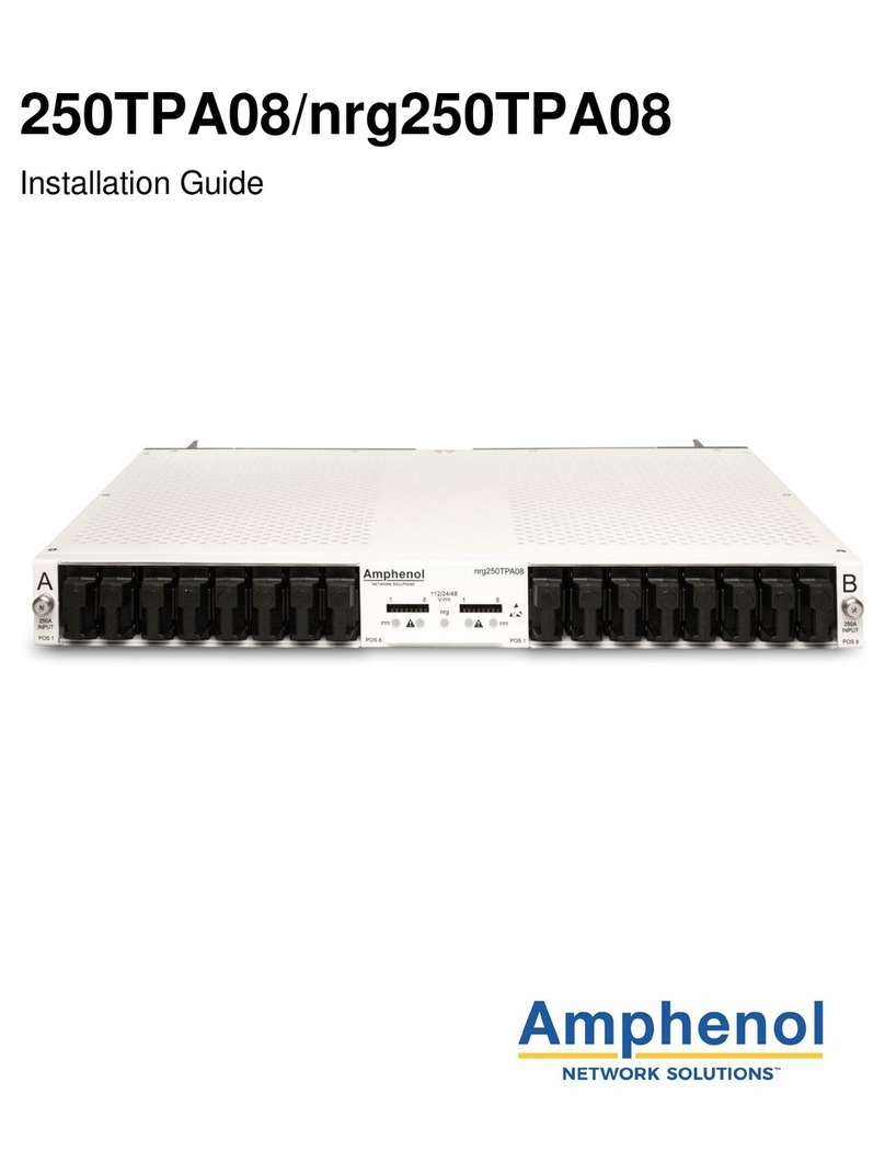
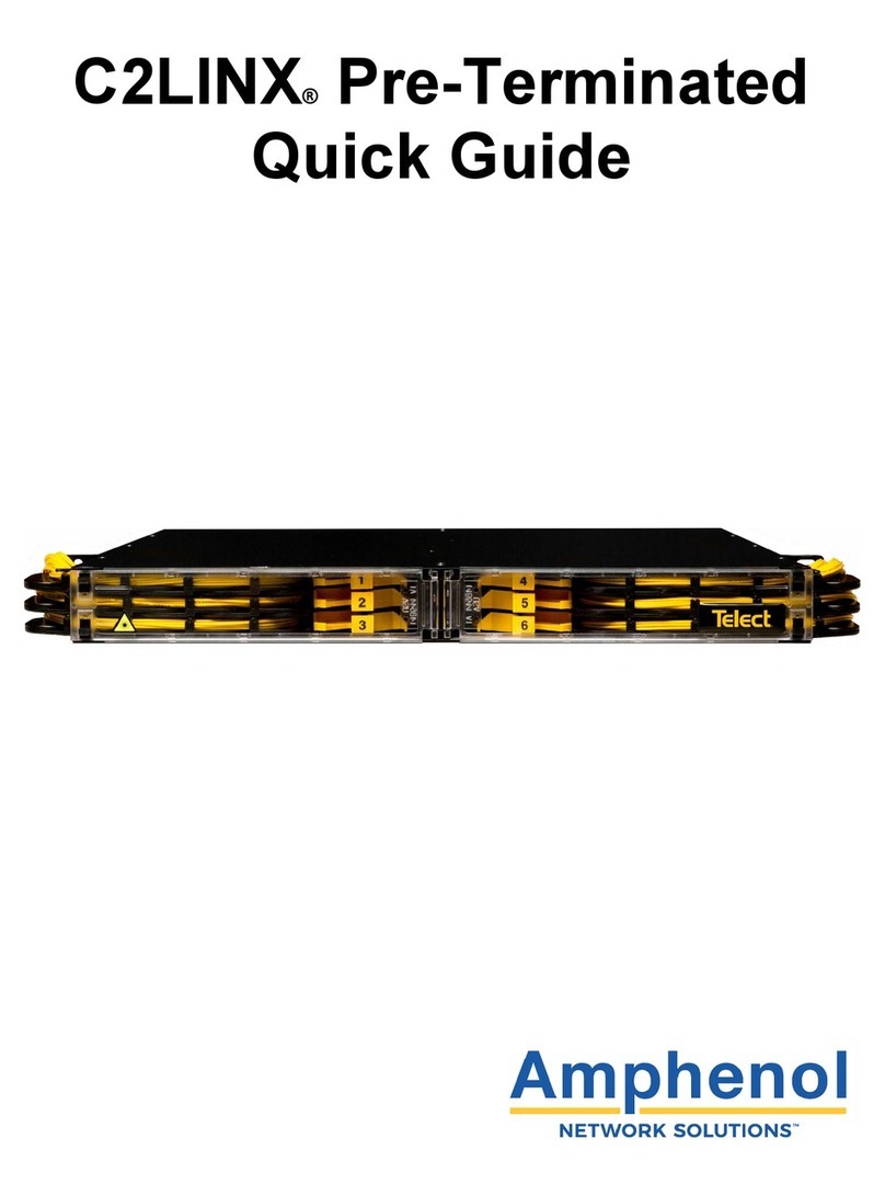
Amphenol C2LINX Series User manual

C2LINX
Installation Guide
®

2
C2LINX
Amphenol Network Solutions
All rights reserved. 04.13.20 150717 A0
509.926.6000 —amphenol-ns.com
®
Installation Guide, Part Number 150717
Copyright 2019, Amphenol Network Solutions, All Rights Reserved.
Amphenol Network Solutions
22425 East Appleway Ave. # 11
Liberty Lake, WA 99019
Amphenol Network Solutions assumes no liability from the application or use of these products. Neither does
Amphenol Network Solutions convey any license under its patent rights nor the patent rights of others. This
document and the products described herein are subject to change without notice.
About
Amphenol Network Solutions is a global innovative original equipment manufacturer that serves the data and
communications markets. We design, manufacture, and distribute products for customers who need an end to
end solution for network connectivity, fiber, power distribution, and rack management. We collaborate with our
customers to deliver product solutions that exceed expectations with innovative designs and world class quality.
Amphenol Network Solutions is the industry thought leader on network cable management.
Technical Support
Email: support@amphenol-ns.com
Phone: 509.926.6000

3
C2LINX
Amphenol Network Solutions
All rights reserved. 04.13.20 150717 A0
509.926.6000 —amphenol-ns.com
®
Table of Contents
C2LINX ......................................................................................................................................................... 1
1. Introduction............................................................................................................................................... 7
1.1 About this Guide ................................................................................................................................. 7
1.2 Terminology........................................................................................................................................ 8
2. C2LINX Overview..................................................................................................................................... 8
2.1 General Description............................................................................................................................ 8
2.2 Panel Components ............................................................................................................................. 8
2.2.1 Trays............................................................................................................................................ 8
2.2.2 HD Links...................................................................................................................................... 9
2.2.3 Chassis Wall Links ...................................................................................................................... 9
2.2.4 Chassis Doors ............................................................................................................................. 9
2.2.5 Designation Cards..................................................................................................................... 10
2.2.6 Mounting Brackets..................................................................................................................... 10
2.3 Panel Module Overview.................................................................................................................... 10
3. Installation Considerations ..................................................................................................................... 11
3.1 Unpacking......................................................................................................................................... 11
3.1.1 Contents .................................................................................................................................... 11
3.2 Inspection ......................................................................................................................................... 12
3.3 Installation Guidelines....................................................................................................................... 12
3.4 Location and Space.......................................................................................................................... 12
3.4.1 Rack vs. Cabinet ....................................................................................................................... 12
3.5 Tools and Equipment........................................................................................................................ 13
4. C2LINX Chassis Installation................................................................................................................... 13
4.1 Install Mounting Brackets on the C2LINX Chassis........................................................................... 13
4.2 Installing the Chassis on the Rack ................................................................................................... 14
4.3 C2LINX Opening Doors.................................................................................................................... 14
4.3.1 C2LINX Front Door.................................................................................................................... 14
4.3.2 C2LINX Rear Door .................................................................................................................... 15
4.4 Chassis Wall Links ....................................................................................................................... 15
4.5 Designation Labels........................................................................................................................... 16
4.5.1 Install Designation Labels.......................................................................................................... 17
5. C2LINX Pre-Terminated Module Installation.......................................................................................... 17
5.1 Packaging......................................................................................................................................... 18
5.2 Unpacking C2LINX Pre-Terminated Modules .................................................................................. 18
5.3 Installing Rack Mount Slide Brackets ............................................................................................... 19
5.4 Installing Chassis in Rack................................................................................................................. 20
5.5 Releasing Rack Bracket ................................................................................................................... 21
5.6 Chassis Wall Links............................................................................................................................ 22
5.7 Removing Back Cover and Door...................................................................................................... 23
6. C2LINX Module Installation.................................................................................................................... 24
6.1 Opening the Tray.............................................................................................................................. 24
6.2 Closing a Tray................................................................................................................................... 24
6.3 Installing a Module............................................................................................................................ 25
6.4 Removing a Module.......................................................................................................................... 26

4
C2LINX
Amphenol Network Solutions
All rights reserved. 04.13.20 150717 A0
509.926.6000 —amphenol-ns.com
®
6.5 Configuring and Installing Patch Modules........................................................................................ 26
6.6 Adding/Replacing Fiber Jumpers to an Installed Patch Module....................................................... 29
6.7 Installing MPO Modules.................................................................................................................... 31
6.8 Installing Pre-Terminated Modules................................................................................................... 31
6.9 Splitter Modules................................................................................................................................ 33
6.10 Splice Modules ............................................................................................................................... 33
6.10.1 Connecting Fiber Jumpers ...................................................................................................... 37
7. Seismic Latch Installation....................................................................................................................... 38
8. Service.................................................................................................................................................... 41
8.1 Owner Maintenance.......................................................................................................................... 41
8.1.1 High Insertion Loss and the Importance of Cleaning Connectors and Adapters ...................... 41
9. Customer Service and Ordering Information.......................................................................................... 42
9.1 In-Warranty Service.......................................................................................................................... 42
9.2 Out-of-Warranty Service................................................................................................................... 42
9.3 Repackage for Shipment.................................................................................................................. 42
9.4 Ordering Replacement Parts............................................................................................................ 42
9.4.1 Replacing a Tray ....................................................................................................................... 42
9.4.2 Replacing a Door....................................................................................................................... 43
9.4.3 Replacing Links ......................................................................................................................... 43

5
C2LINX
Amphenol Network Solutions
All rights reserved. 04.13.20 150717 A0
509.926.6000 —amphenol-ns.com
®
List of Figures
Fig. 1-1: C2LINX 1RU chassis...................................................................................................................... 7
Fig. 2-1: C2LINX tray.................................................................................................................................... 8
Fig. 2-2: HD Links......................................................................................................................................... 9
Fig. 2-3: Chassis wall links ........................................................................................................................... 9
Fig. 2-4: Chassis door................................................................................................................................... 9
Fig. 2-5: Designation label.......................................................................................................................... 10
Fig. 2-6: Mounting brackets........................................................................................................................ 10
Fig. 3-1: C2LINX working footprint ............................................................................................................. 13
Fig. 4-1: Left side mounting bracket ........................................................................................................... 13
Fig. 4-2: Mounting the bracket to the chassis............................................................................................. 14
Fig. 4-3: Mounting the bracket to the rack.................................................................................................. 14
Fig. 4-4: Opening and closing the doors..................................................................................................... 14
Fig. 4-5: Rear door...................................................................................................................................... 15
Fig. 4-6: Installing chassis wall links........................................................................................................... 16
Fig. 4-7: Installing the tray links to trays..................................................................................................... 16
Fig. 4-8: Designation label.......................................................................................................................... 16
Fig. 4-9: Installing designation label........................................................................................................... 17
Fig. 5-1: Packaging..................................................................................................................................... 18
Fig. 5-2: Removing packaging.................................................................................................................... 18
Fig. 5-3: Removing outer box..................................................................................................................... 19
Fig. 5-4: Mounting brackets to the rack...................................................................................................... 19
Fig. 5-5: Sliding chassis into mounting brackets ........................................................................................ 20
Fig. 5-7: Chassis set in rack ....................................................................................................................... 20
Fig. 5-6: Tab fully engaged showing........................................................................................................... 20
Fig. 5-8: Setting front bracket screws......................................................................................................... 21
Fig. 5-9: Locking tabs ................................................................................................................................. 21
Fig. 5-10: Installing chassis wall links......................................................................................................... 22
Fig. 5-11: Installing tray links to trays ......................................................................................................... 22
Fig. 5-12: Removing thumb screws............................................................................................................ 23
Fig. 5-13: Removing back door and cover thumbscrew(s)......................................................................... 23
Fig. 6-1: Yellow handle............................................................................................................................... 24
Fig. 6-2: Opening a tray.............................................................................................................................. 24
Fig. 6-3: Closing a tray by pushing on the yellow handle........................................................................... 25
Fig. 6-4: Tray closing and in locked position .............................................................................................. 25
Fig. 6-5: Installing a module ....................................................................................................................... 25
Fig. 6-6: Installing fiber jumpers ................................................................................................................. 26
Fig. 6-7: Labeling the fiber ports................................................................................................................. 27
Fig. 6-8: Installing the patch module........................................................................................................... 27
Fig. 6-9: Routing cable through the face plate ........................................................................................... 28
Fig. 6-10: Routing cable through the links.................................................................................................. 28
Fig. 6-11: Routing fiber through the links.................................................................................................... 29
Fig. 6-12: Installing a fiber on the shuttle.................................................................................................... 29
Fig. 6-13: Connecting the fiber ................................................................................................................... 30
Fig. 6-14: Fiber inspection adapters........................................................................................................... 30
Fig. 6-15: Routing fiber through the links.................................................................................................... 31
Fig. 6-16: Routing fibers through the links.................................................................................................. 32
Fig. 6-17: Opening the splice cassette....................................................................................................... 34
Fig. 6-18: Recommended cable routing ..................................................................................................... 34
Fig. 6-19: Laying out slack loops................................................................................................................ 35
Fig. 6-20: Coiling fiber into cassette........................................................................................................... 36

6
C2LINX
Amphenol Network Solutions
All rights reserved. 04.13.20 150717 A0
509.926.6000 —amphenol-ns.com
®
Fig. 6-21: Tuck fiber under fingers.............................................................................................................. 36
Fig. 6-22: Re-install clear cover.................................................................................................................. 36
Fig. 7-1: Left arm link.................................................................................................................................. 38
Fig. 7-2: Alignment of hinge........................................................................................................................ 38
Fig. 7-3: Right arm link................................................................................................................................ 39
Fig. 7-4: Alignment of hinge........................................................................................................................ 39
Fig. 7-5: Chassis wall link locations............................................................................................................ 40
Fig. 7-6: Locking the door........................................................................................................................... 40
Fig. 9-1: Removing/replacing the door ....................................................................................................... 43

7
C2LINX
Amphenol Network Solutions
All rights reserved. 04.13.20 150717 A0
509.926.6000 —amphenol-ns.com
®
1. Introduction
This installation guide gives directions on:
•How to install the C2LINX chassis on either a 19- or 23-inch rack or cabinet
•How to install patch modules, patch-and-splice modules, pre-terminated modules, splitter and
MPO modules
•How to route and secure the fiber optic cable within the chassis
1.1 About this Guide
This manual provides a comprehensive overview of and installation guidelines for the C2LINX chassis. While
care has been taken to define all necessary information, complete details may not be covered. If you have any
questions, contact Amphenol Network Solutions Technical Support at support@amphenol-ns.com or call
509-926-6000.
Throughout this guide, select information is highlighted in the form of Notes, Alerts, Cautions and Warnings.
These notifications are prominent, and their importance is indicated as follows:
NOTE: General information to which the user should pay special attention.
ALERT! Important information and/or instructions to which the user should adhere.
CAUTION! Indicates a hazardous situation, which could result in minor or moderate injury.
WARNING! Indicates a potentially hazardous situation which could result in death or serious injury.
Amphenol Network Solutions assumes no liability from the application or use of these products. Amphenol
Network Solutions does not convey any license under its patent rights of others. This document and the products
described herein are subject to change without notice.
Fig. 1-1: C2LINX 1RU chassis

8
C2LINX
Amphenol Network Solutions
All rights reserved. 04.13.20 150717 A0
509.926.6000 —amphenol-ns.com
®
1.2 Terminology
The following is a list of acronyms and abbreviations used throughout this manual.
2. C2LINX Overview
2.1 General Description
The C2LINX chassis is a high-density optical distribution platform. It offers the market’s best cable management
at the highest termination density in the smallest footprint.
* NOTE: Amphenol Network Solutions requires the use of G.657.A1 fiber and recommends using G.657.A2 fiber.
1.2 and 1.6mm fiber jumpers are recommended as well as short boots.
2.2 Panel Components
2.2.1 Trays
Left and right trays of the C2LINX chassis slide in and out by pulling up and out on the yellow locking handles.
This allows easy access to the modules. Each tray holds two modules.
Acronym/Abbreviation
Term
CWDM
Coarse Wavelength Division Multiplexing
DWDM
Dense Wavelength Division Multiplexing
IF
Intra Facility Fiber
IFC
Intra Facility Cable
LC
Local Connector
MPO
Multi-fiber Push-On optical fiber module interface type
NE
Network Element
NEBS
Network Equipment Building System (telecommunications product safety
equipment rating)
PC
Physical Contact fiber optic connector (single or multimode)
SC
Standard Connector
TIA
Telecommunications Industry Association
TIA/EIA-568 B.3
Telecommunication standard for commercial cabling
TUV
Technical Inspection Association (global product certification compliance marking)
UL
Underwriter Laboratories (electrical standards)
UPC
Ultra Physical Contact fiber optic connector (single or multimode)
APC
Angled Physical Contact fiber optic connector (single or multimode)
Fig. 2-1: C2LINX tray

9
C2LINX
Amphenol Network Solutions
All rights reserved. 04.13.20 150717 A0
509.926.6000 —amphenol-ns.com
®
2.2.2 HD Links
HD Links, the fiber cable routing arms, guide and manage fiber, preventing overbending or tugging of the fibers
that can lead to fractures and attenuation.
2.2.3 Chassis Wall Links
Chassis wall links attach the links to the chassis.
2.2.4 Chassis Doors
Chassis doors open toward the center of the chassis for space optimization. They are easy to remove and re-
install if necessary. See Section 5 for pre-terminated rear door installation.
Left
Right
Fig. 2-2: HD Links
Fig. 2-3: Chassis wall links
Fig. 2-4: Chassis door

10
C2LINX
Amphenol Network Solutions
All rights reserved. 04.13.20 150717 A0
509.926.6000 —amphenol-ns.com
®
2.2.5 Designation Cards
Designation cards are located on each of the chassis doors. Please fill out the designation cards with the location
of each cable for future additions, replacements and maintenance.
2.2.6 Mounting Brackets
Mounting brackets are located on the sides of the chassis. These dedicated mounting brackets let you adjust the
chassis forward or backward in a 19-inch rack. Extension brackets are available for mounting the chassis to a 23-
inch rack or cabinet. See Section 5 for installing pre-terminated mounting hardware.
When installing the chassis in a data center rack, install the brackets as far forward as possible. This will allow for
less cable management issues when fiber is installed in the chassis.
2.3 Panel Module Overview
C2LINX modules are interchangeable within the C2LINX trays, allowing for the ability to mix and match different
modules and configurations.
The following modules are available for C2LINX:
•Patch
•Splice
•Pre-terminated
•MPO breakout
•Advanced Optical Modules including:
oSplitters
oTAPs
oCWDM
oDWDM
Fig. 2-6: Mounting brackets
Fig. 2-5: Designation label

11
C2LINX
Amphenol Network Solutions
All rights reserved. 04.13.20 150717 A0
509.926.6000 —amphenol-ns.com
®
3. Installation Considerations
WARNING! Verify all connections meet requirements specified in local electric codes or operating
company guidelines before supplying power. Unit must be protected by a listed circuit breaker or
branch-rated fuse sufficient to interrupt power levels.
WARNING! Use of fully insulated tools is required when working with any AC or DC circuits.
WARNING! Fiber cables transmit invisible infrared light. To avoid eye damage or blindness, never
look directly into fibers or connectors.
CAUTION! These instructions presume you have verified the Amphenol Network Solutions equipment
being installed is compatible with the rest of the system including power, ground, circuit protection,
signal characteristics, equipment from other vendors, and local codes or ordinances.
ALERT! This product must be installed and maintained only by qualified technicians.
ALERT! Install this system according to company requirements. It is recommended you install the
system in a Restricted Access Location (RAL) where access is limited through use of tool, lock and
key, or other means of security and be controlled by the authority responsible for the location.
ALERT! Prior to panel installation, ensure there is enough space in front and rear to access cabling.
ALERT! Only use components and crimping tools approved by agencies or certifying bodies
recognized in your country or region, such as Underwriter’s Laboratories (UL), TUV, etc.
ALERT! Do not stand on fiber or fiber cables.
3.1 Unpacking
Upon receipt of your order, carefully unpack contents and compare it with the packing list and the order placed.
While items described below are a comprehensive list that includes the C2LINX chassis, trays, brackets and
doors, the contents of your order may vary.
3.1.1 Contents
•Installation guide
•Trays –installed
Chassis
Dimensions
Weight
1RU
1.75"H x 17.5"W x 18.25"D
15 lbs.
2RU
3.5"H x 17.5"W x 18.25"D
24 lbs.
4RU
7"H x 17.5"W x 18.25"D
35 lbs.

12
C2LINX
Amphenol Network Solutions
All rights reserved. 04.13.20 150717 A0
509.926.6000 —amphenol-ns.com
®
•Removeable doors –installed
•Designation labels (front and rear) –installed
•Mounting brackets for 19-inch rack or cabinet –installed
•Extension brackets for 23-inch mounting
•Links –require installation
3.2 Inspection
Please report any defective or missing parts to Amphenol Network Solutions Quality at quality@amphenol-ns.com
or call 509-926-6000. Keep all documentation that comes with your shipment.
Please read and understand all instructions before starting installation. If you have any questions, contact
Amphenol Network Solutions Technical Support at support@amphenol-ns.com or call 509-926-6000.
Exercise care when unpacking and setting the equipment in place. Amphenol Network Solutions is not liable for
transit damage. If the product is damaged, please report it to the carrier and contact Amphenol Network Solutions
Quality.
3.3 Installation Guidelines
Elevated Operating Ambient Temperature
If installed in a closed or multi-unit rack assembly, the operating ambient temperature of the rack environment
may be greater than room ambient. Consider installing the equipment in an environment compatible with the
maximum ambient temperature (Tma) specified by the manufacturer.
Mechanical Loading
Avoid uneven mechanical loading in the rack. This can cause hazardous conditions.
3.4 Location and Space
The C2LINX chassis requires space in the front and rear for access to patching, splicing and cabling.
Leave as much side clearance for tray and worker access as required by your application or local
regulations. Plan the input/output, upward/downward (cable feed) layout of each module and its position in
the chassis before beginning C2LINX chassis installation.
The C2LINX chassis adapts to standard 19- or 23-inch ETSI racks with EIA, ETSI and WECO spacing and
nominal 5½-inch extensions beyond the front rack flange.
Depending on the chassis, 1RU, 2RU or 4RU are required to mount the chassis. This can either be in a rack or a
cabinet.
The chassis comes equipped with 19-inch mounting brackets and extension brackets for 23-inch mounting. Order
additional brackets by calling Amphenol Network Solutions at 509-926-6000.
Leave 1RU of space on top of each chassis to allow enough room to access and remove the top modules if
needed.
3.4.1 Rack vs. Cabinet
If mounting in a cabinet, mount the chassis so the links do not interfere with the cabinet spacer bar. The image
below depicts the area required for the chassis to function properly.

13
C2LINX
Amphenol Network Solutions
All rights reserved. 04.13.20 150717 A0
509.926.6000 —amphenol-ns.com
®
3.5 Tools and Equipment
Phillips and flat-head screwdrivers are required. No other tools are needed to assemble the C2LINX chassis and
corresponding modules. If links need replacement on the chassis, needle-nosed pliers are required to separate
the links.
4. C2LINX Chassis Installation
Please read these instructions carefully before installation. If you need assistance, call Amphenol Network
Solutions at 509-926-6000 or email us at support@amphenol-ns.com.
Inspect equipment after unpacking and compare it to the packing list.
Immediately report any shipping damage, defects or missing parts to Amphenol Network Solutions. Keep all
documentation that comes with your shipment.
Amphenol Network Solutions is not liable for shipping damage. If the product is damaged, notify the carrier and
call Amphenol Network Solutions at 509-926-6000 for further recourse.
NOTE: For service or warranty information, please visit amphenol-ns.com and click on the Support tab, email us
at support@amphenol-ns.com or phone us at 509-926-6000.
This section covers how to prepare and mount the C2LINX chassis and corresponding modules.
4.1 Install Mounting Brackets on the C2LINX Chassis
C2LINX chassis includes two mounting brackets and two extension brackets, non-interchangeable, one per side,
to attach the C2LINX chassis to a 19-inch or 23-inch EIA, ETSI or WECO rack.
Fig. 4-1: Left side mounting bracket
Note: Image shows mounting bracket marked for left side
Fig. 3-1: C2LINX working footprint

14
C2LINX
Amphenol Network Solutions
All rights reserved. 04.13.20 150717 A0
509.926.6000 —amphenol-ns.com
®
The mounting brackets arrived pre-installed on the chassis. If the position of the brackets needs to be changed, a
multi-hole pattern allows the chassis to be offset toward front or back in accordance with customer need. See
Section 5 for installing mounting brackets for pre-terminated modules.
4.2 Installing the Chassis on the Rack
1. Using a Phillips head screwdriver and the provided 12-24 screws, install the chassis on the front of the rack
by aligning the mounting holes in the bracket with the holes in the rack. Two screws per side are used to
attach the chassis to the rack.
4.3 C2LINX Opening Doors
4.3.1 C2LINX Front Door
Plastic latches are located on the end of each door.
1. Pinch latches together on the doors.
2. Pivot door on the center hinge to open.
Front view
Side view
Fig. 4-2: Mounting the bracket to the chassis
Fig. 4-3: Mounting the bracket to the rack
Fig. 4-4: Opening and closing the doors

15
C2LINX
Amphenol Network Solutions
All rights reserved. 04.13.20 150717 A0
509.926.6000 —amphenol-ns.com
®
4.3.2 C2LINX Rear Door
Plastic latches are located on the end of each door.
1. Pinch latches together on the doors.
2. Pivot door on the center hinge to open.
4.4 Chassis Wall Links
Chassis wall links attach the side wall of the chassis. Front and rear chassis wall links are not installed to avoid
interferences with rail racks or cabinets. Once the chassis is mounted in the rack, you may install the chassis wall
links.
Each link is marked L for left and R for right. They are installed on the appropriate side of the chassis by inserting
the bottom clips into the square notches in the plastic rails and then pushing down the top clip to lock in place.
They can be removed by pushing down on the top clip and then pulling the link up and out.
1. Remove chassis wall links from packaging.
2. Starting with the bottom-most tray. Attach the two bottom clips of the chassis wall links into the square
notches on the chassis side wall (Fig. 4-6).
3. Rotate chassis wall links upward until the top clip snaps into place on the chassis side wall (Fig. 4-6).
4. Attach other end of links to tray by squeezing both centers together until they click into place on the bottom-
most tray (Fig. 4-7).
5. Repeat steps on all right and left trays.
Fig. 4-5: Rear door

16
C2LINX
Amphenol Network Solutions
All rights reserved. 04.13.20 150717 A0
509.926.6000 —amphenol-ns.com
®
4.5 Designation Labels
Designation labels are located on each C2LINX door. Designation labels are used to identify adapter fiber jumper
information at the front of the panel and connector pigtail fiber information at the rear of the panel.
Fig. 4-7: Installing the tray links to trays
Fig. 4-8: Designation label
Fig. 4-6: Installing chassis wall links

17
C2LINX
Amphenol Network Solutions
All rights reserved. 04.13.20 150717 A0
509.926.6000 —amphenol-ns.com
®
4.5.1 Install Designation Labels
Designations label are marked as FRONT SIDE and REAR SIDE on the bottom corner.
1. Open the door to the front or rear of the C2LINX chassis (Section 4.3).
2. Slide the designation label into the small tabs on the door.
5. C2LINX Pre-Terminated Module Installation
Please read these instructions carefully before installation. If you need assistance, call Amphenol Network
Solutions at 509-926-6000 or email us at support@amphenol-ns.com.
Inspect equipment after unpacking and compare it to the packing list.
Immediately report any shipping damage, defects or missing parts to Amphenol Network Solutions. Keep all
documentation that comes with your shipment.
Amphenol Network Solutions is not liable for shipping damage. If the product is damaged, notify the carrier and
call Amphenol Network Solutions at 509-926-6000 for further recourse.
NOTE: For service or warranty information, please visit Amphenol-ns.com and click on the Support tab, email us
at support@amphenol-ns.com or phone us at 509-926-6000.
This section covers how to prepare and mount the C2LINX chassis and corresponding modules.
Fig. 4-9: Installing designation label

18
C2LINX
Amphenol Network Solutions
All rights reserved. 04.13.20 150717 A0
509.926.6000 —amphenol-ns.com
®
5.1 Packaging
The Amphenol Network Solutions C2LINX Pre-Terminated Modules are shipped in a cardboard box. The
cardboard box is easily disassembled for quick deployment of fiber.
See Pre-Terminated Quick Start Guide if you are adding a C2LINX chassis or fiber.
If this is your first installation of C2LINX Pre-Terminated Modules, continue through the full installation of the
product.
5.2 Unpacking C2LINX Pre-Terminated Modules
1. Remove top cover of box and corner pieces.
Fig. 5-1: Packaging
Fig. 5-2: Removing packaging

19
C2LINX
Amphenol Network Solutions
All rights reserved. 04.13.20 150717 A0
509.926.6000 —amphenol-ns.com
®
2. Remove outer box of packaging by pulling box up and away from spool.
3. Remove cellophane wrap from the spool and cable.
4. Fiber can be unspooled either manually by unraveling the cable or with the aid of a turntable.
5.3 Installing Rack Mount Slide Brackets
Install 7½-inch rack-mount slide brackets to the desired RU space on the rack.
1. Remove rack-mount slide brackets from packaging.
2. Align mounting holes on the bracket with the holes on the front of the rack.
3. Using a Phillips head screwdriver, install the slide brackets onto the rails with the 12-24 screws provided.
NOTE: Do not tighten securely to the rack. This allows easier alignment for chassis to slide into correct position.
NOTE: Use two screws per side when attaching the chassis to the rack.
Fig. 5-3: Removing outer box
Fig. 5-4: Mounting brackets to the rack

20
C2LINX
Amphenol Network Solutions
All rights reserved. 04.13.20 150717 A0
509.926.6000 —amphenol-ns.com
®
5.4 Installing Chassis in Rack
1. Remove chassis from packaging by holding onto both sides of the chassis.
Warning: Do not hold chassis from fiber or links.
2. Lift chassis up and out of protective packaging.
3. Align rail guides that are attached to the chassis to the pre-installed mounting brackets from the rear
of rack.
NOTE: Rail guides are pre-installed to chassis. You will not need to install them after unpacking.
4. Push the chassis all the way forward. You will hear a click on both sides of the chassis. Ensure tabs have fully
engaged.
Fig. 5-5: Sliding chassis into mounting brackets
Fig. 5-6: Tab fully engaged showing
Fig. 5-7: Chassis set in rack
Rear
Rear
Other manuals for C2LINX Series
2
Table of contents
Other Amphenol Network Hardware manuals