forest river WIDE BODY Series User manual

OPERATING
MANUAL
Mobile Restroom Trailer
Forest River Cargo 3731 California Road Elkhart, IN 46514

Welcome to Forest River
Forest River is one of the World’s largest manufacturers
of Cargo, Auto transport, Specialty trailers, and
Recreational Vehicles.
At Forest River, we have attempted to design and
manufacture a very functional and serviceable portable
Restroom facility. Using the best materials we have been
able to obtain, we feel that this product will offer durability
and performance for a long period of time.
Thank You

Table of Contents
•Introduction
•Table of Contents
•Knowing your trailer: Pictures and Descriptions
•Wiring Diagram
•Pre-Trip check list and Hooking Up
•Set Up – Leveling & Assembly –
Steps, Porches, & Railings
-- Electrical & Water Hook-Up
•Operation – Climate Control – LED Waste Tank Sensor -
Doors - Mirrors, Soap, & Towel Dispensers
•Tear Down / Dismantling
•Winterizing - City Fill & On-Board Tanks
•Routine Trailer Maintenance
•General Trailer Maintenance
•Reporting Safety Defects
•Warranties
•Replacement Parts
Knowing Your Trailer
View of theTrailer with Steps and Porches Retracted. Side View showing Steps, Railings,
Railings are Stored in the Front Carrier & Porches Assembled
Rubber Draw Latch - Holds the Bracket - Holds Porch
Porch Steps in Retracted Position in Retracted Position
View of Rail Locking Pin at Bottom Leveling Foot for Steps
with the various components of your trailer
Please review these pictures and descriptions so you can familiarize yourself

Railing Installed at Top Leveling Jack
Exterior RV Style Electrical Cord Hook-Up City Water Fill
Front of Trailer Showing Porch Light
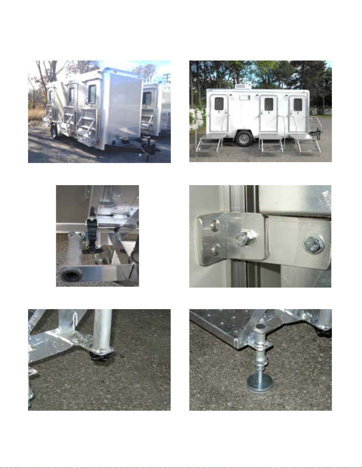
Pump Out Valve and Wash Out Port
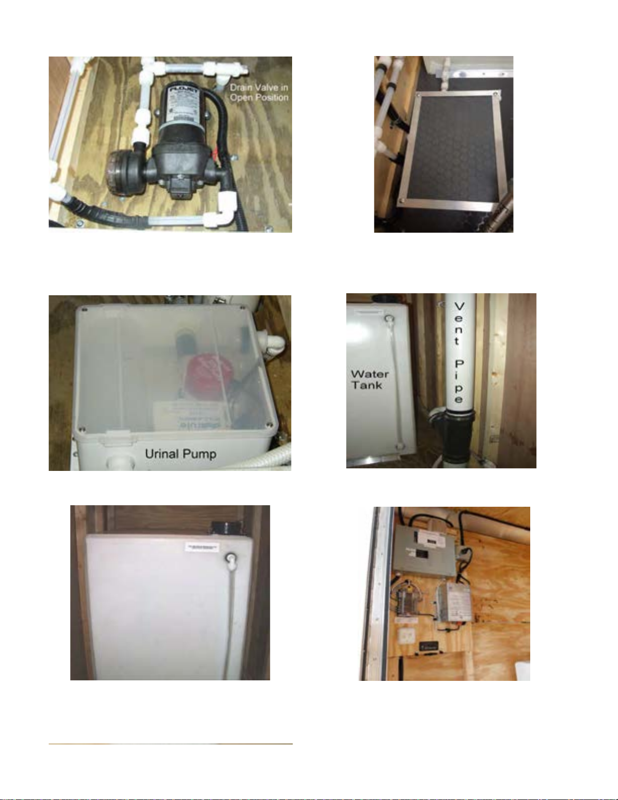
Fresh Water Pump (exposed) Fresh Water Pump with Cover
Urinal Pump View of Vent Pipe and Fresh Water Tank
with Level Indicator Tube
On-Board Fresh Water Tank Showing Electrical Panel
Fill Cap on Top of Tank
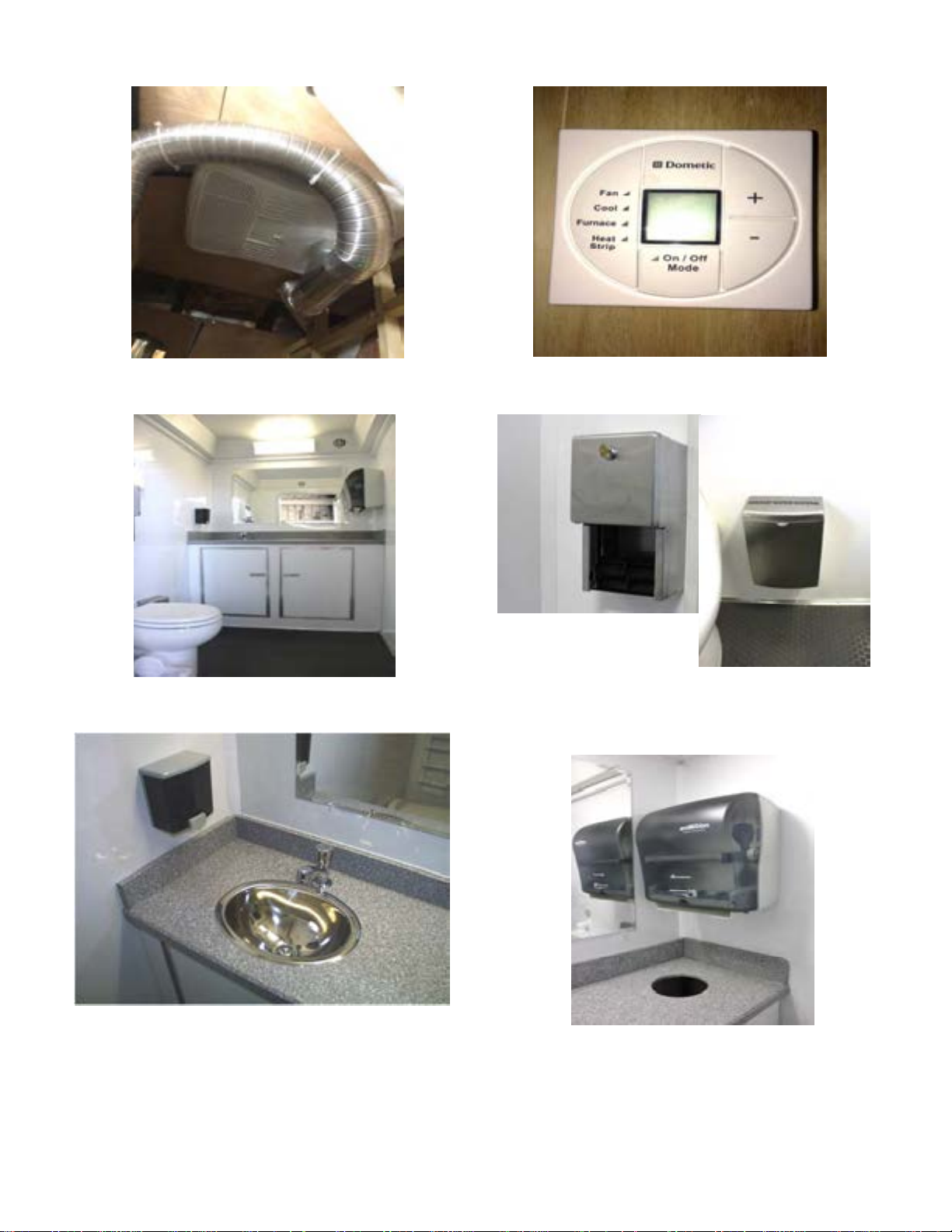
Roof A/C and Ducts A/C Climate Control
View of Women's Restroom Example of Toilet Paper Dispenser
and Sanitary Napkin Recepticle
Sink and Soap Dispenser Paper Towel Dispenser and
Trash Disposal Access
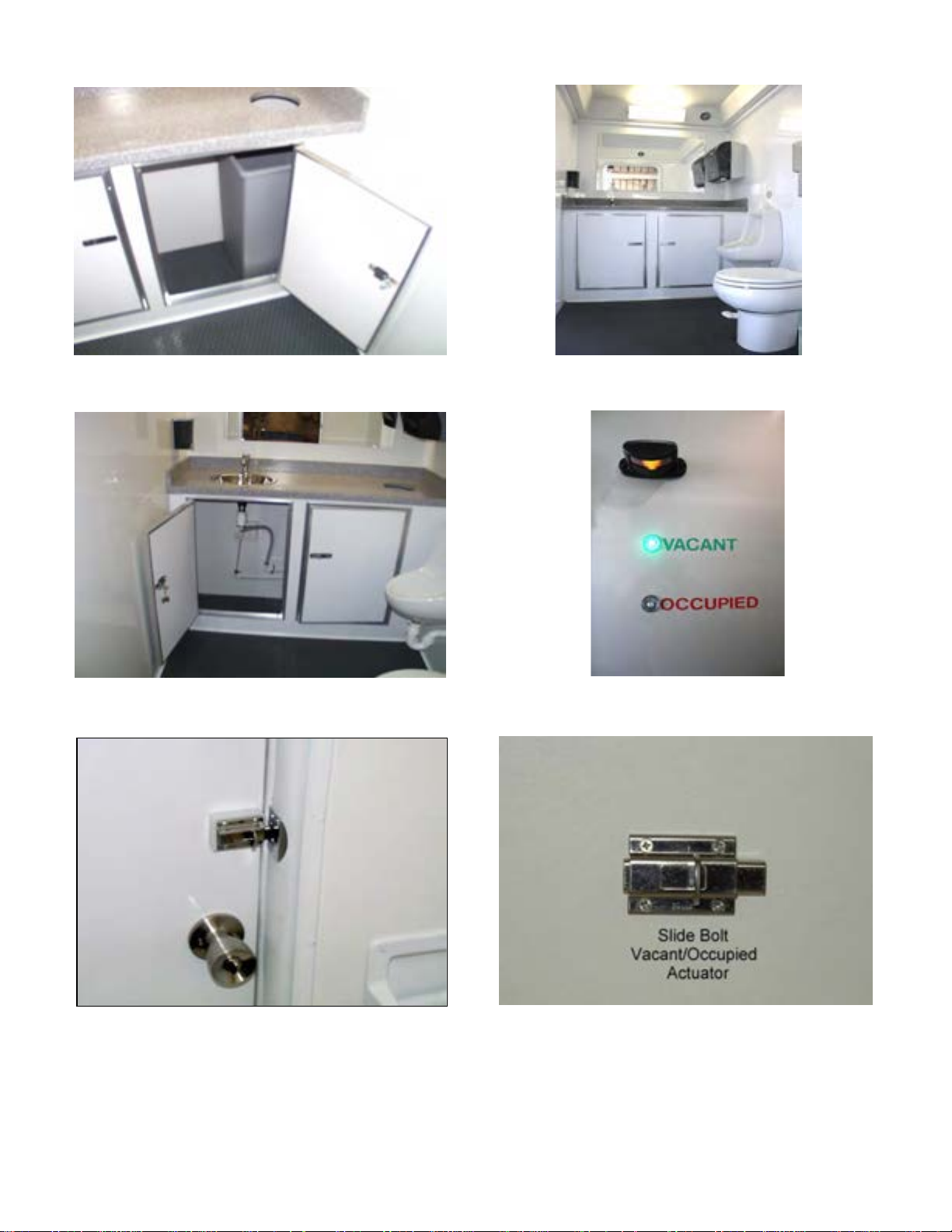
View of Trash Collection Recepticle View of Men's Restroom
In Locking Base Cabinet
View of Sink Drain Set-Up Inside Century Series Vacant / Occupied Lights
Lockable Base Cabinet
Slide Bolt that Operates Vacant / Occupied Vacant / Occupied Slide Bolt
Indicators


Pre-Trip Checklist
This is the most important thing you should look at before using your new trailer. Please take
your time, and make sure you go over this list completely! A description of how these parts work and
how they should be properly checked is included in the Trailer Owner’s Manual.
•Hitch and coupler w/safety pin
•Safety chains crossed and secured properly
•All Jacks are up
•All running lights, brake lights, and turn signals functioning
•Brakes, brake controller, and breakaway system
•Proper tire pressure and tire condition on trailer and tow vehicle
•Wheel lug nuts tightened
•Doors, windows, and roof vents closed and secured
•Tie-down Steps, Porches, & Railings
•Proper load distribution
•Both Fresh & Waste Water tanks must be empty prior to transporting the trailer.
Always remember that some common causes of accidents are (1) driver error, (2) failure to
match your road speed with road conditions, and (3) improper loading.
Safety chains: Be sure to always connect the safety chains by crossing them beneath the coupler
when hooking up your trailer. Crossing your safety chains will create a cradle to catch the tongue in
case of disconnect from the hitch. Allow enough chain for turning, if too long, then they should be
shortened (just simply twist them). If they look like they have been over-stressed, they should be
replaced. In some states it is required by law, that you cross your safety chains.
Brakes: Forest River trailers come with many different types of brake options. Repair and service
information for each available type of brake can be found in the Axle Manufacturer’s Service Manual.
Please follow all of the Axle Manufacturer’s instructions concerning brakes. Remember that failure to
follow instructions could result in loss of warranty. Brakes on new trailers usually tend to “pull” or
pulsate, but don’t worry, this is normal. Remember that not all Forest River trailers are equipped with
brakes.
Tire pressure: The proper air pressure for your tires is printed on the sidewall of the tire. Air
pressure should always be checked when tires are cold for the most accurate reading. You must not
raise or lower your air pressure to meet your load. Serious injury may result in under and over
inflation. Excessive wear and tear will also result if recommended pressure is not met. You must
avoid, if possible, any chuckholes, curbs, or other hazards in the road.
Hitch and coupler: You must correctly match your tow vehicle to your trailer. It is essential that
your tow vehicle can handle the total trailer weight (GVWR). You should also check to see that the
hitch weight carrying capacity of your tow vehicle matches the loaded tongue weight of your trailer.
If you have a brake controller, then you want it to match with the number of braking wheels on your
trailer. The electrical wiring of your tow vehicle needs to match the wiring on your trailer. It is very
important that the ball on your hitch matches the coupler size on the trailer.
Proper load distribution: All Forest River trailers are carefully designed to maintain a proper hitch
weight when the trailer is evenly loaded. If improperly loaded, your trailer can become very unstable

and difficult to control on the road. Uneven loading and improper hitch weight can make steering
difficult and result in unsafe stopping and braking of the trailer and the tow vehicle.
For bumper-hitch trailers, always load 60 percent of the cargo weight evenly in front of the
axles. For Goosenecks, load 70% of the weight in front of the axles. This will result in an
approximate 10 percent of the loaded trailer weight on the hitch. Hitch weight should never be
less than 10 percent of the gross vehicle weight (trailer plus payload).
Distribute load as shown below:
Tips for the beginner – Turning & Backing up
Always remember when turning, that the trailer makes tighter and quicker turns than your tow
vehicle. To help compensate for this, please allow as much space as possible when turning so that the
trailer will not jump the curb or hit any obstacles. When backing up place your hand on the bottom of
the steering wheel while watching in your outside mirror. If you want the rear of the trailer to turn
right move your hand right, and if you want the rear of the trailer to turn left then move your hand left.
Please always remember to check the area behind the trailer to see that there are no obstacles in the
way before you begin to back up.
Hitching Up
To ensure safe towing, make sure you have a suitable vehicle, hitch, and trailer. It is the
trailer owner’s responsibility to correctly match the combination of tow vehicle and trailer.
Contact a hitch specialist, who can help you match your tow vehicle and hitch, and equip you
with a properly installed brake controller.
Make sure the ball on your hitch matches the coupler size on the trailer.
•Use the jack to raise the coupler high enough for the hitch ball to slip beneath.
•Release the coupler-locking device (raise the lever).
•Back your tow vehicle into mounting position.
•When properly aligned lower the coupler onto the ball.
•Continue raising the jack until it is fully raised.
•Latch the coupler-locking device (It is very important to lower the lever and insert a pin in the lock hole).
•Connect the safety chains by crossing the chains beneath the coupler and attach them to the tow vehicle.
Allow enough slack for turning, but no dragging (Tip: if chains are too long, simply twist them).
•Connect the electrical plug on the trailer to the plug on the tow vehicle. Check to make sure that all
running, directional, and brake lights are functioning.
•Load properly approx. 60% in front of the axles (you want 10-15% of the trailer and load weight on the
hitch), balance the load side to side, and secure it (you don’t want it getting loose). Don’t overload, go by
acceptable payload ratings or you may void the warranty.
•Take a trial run and familiarize yourself with the handling characteristics of our tow vehicle and trailer.
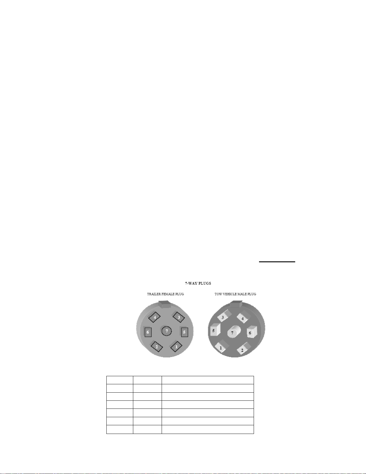
Electrical Wiring
You must have the correct vehicle wiring when using your trailer. Trailers are equipped
with brakes and a 7-way plug. Don’t forget that a ground wire running from the plug back to the
frame of the tow vehicle must be incorporated into proper tow vehicle wiring. WARNING:
Safety chains, hitches, and couplers DO NOT provide adequate grounding by themselves
and can cause electrical failures.
Number Wire Color Function
1
White
Common Ground
2
Blue
Electric Brakes
3
Green
Tail, License, & Running Lights
4
Black
Battery Charge, Hot, & Dome
5
Red
Stop & Left Turn Signal
6
Brown
Stop & Right Turn Signal
7
Yellow
Extra Auxiliary

SET-UP
Please follow these step-by-step procedures. Set-up time will be about ½ hour.
Leveling your unit
Thoroughly inspect the site location. The site should be level and have proper access to
water and electricity. Consider proper facing of the unit for convenient access and adequate
drainage.
After positioning the unit, block the wheels prior to disconnecting from the tow vehicle.
Level the unit from front to back using the front tongue jack. Level the unit side to side by
using the scissor jacks located on each corner.
When setting up the trailer for use, it is important that the stabilizer jack on each corner be
lowered and the trailer leveled. Levels are located on each side of the trailer near the wheel
fenders and on the front and back of the trailer. The levels have been applied to indicate
level when the trailer is actually tilted slightly to the rear, roadside corner. This is to allow
air conditioner condensation to run off that corner rather than over the doorways and for
waste drainage to the Waste Water Tank.
Step Assembly – Century Series
(Tools required: 9/16” Box wrench & Ratchet with 9/16” Socket)
**Do not unlock doors until porches are down and railings are installed**
Release rubber latch under step
Unbolt step latch from trailer
Carefully extend and lower step. Watch for pinch points
Place sand pad under step legs
Remove Thumbscrew from rail tube
Insert railing tube & secure with Thumbscrew
Fasten railing to trailer at bracket
Repeat for other railing
Secure by tightening thumb screws

Step Assembly – Denali/Rainier Series
(Tools required: 9/16” Box wrench & Ratchet with 9/16” Socket)
**Only unlock the one door at a time to access porches and steps**
**Care should be taken to insure the rear door is not damaged during set-up**
Remove porch and step unit from the men’s room
Set porch in the channel under the door
**Immediately install railings on this porch**
Remove Thumbscrew from rail tube
Insert railing tube & secure with Thumbscrew
Fasten railing to trailer at bracket
Repeat for other railing
Secure by tightening thumb screws
Repeat the same process for the female room (and exit sides on a Denali)
Steps, Porches, and Railings
It is also important when lowering each porch and step arrangement, to be certain that the
porch is properly leveled using the screw jacks on each step. Levels are also provided on
each porch for this purpose. Proper leveling of the porches facilitates easier placement of
the step to sidewall railing. The railing is attached by removing the two black thumbscrews,
inserting the railing into the pockets then reapplying the thumbscrews. The sidewall railing
is first inserted into the pocket after removing the thumb screw, then carefully swing the
bracketed end of the railing to meet the sidewall bracket, insert a 3/8” x 1” bolt and secure it
with a self-locking nut. Next re-install the thumbscrew.

Instructions for Lowering and Raising an ADA Unit
1. Position unit on a level and flat area.
2. Located in the mechanical room, there are three (3) switches that control the electrical
jacks that raise and lower the unit.
To lower the unit:
1. Use all three switches to raise the unit so that the axle and tires are off the ground.
2. Remove the pins from both sides of the independent axle system.
3. Use all three switches to lower unit so that it rests completely on the ground.
4. Remove the step(s) from the cube(s) and pin them in place. Adjust leveling feet as
needed.
5. Unbolt and lower the ADA platform. Adjust leveling feet as needed.
6. Remove the ramp sections from the ADA cube. Install ramp sections to the ADA
platform.
7. Install rails for ramp and platform.
To raise the unit:
1. Remove rails, ramps, steps and stow them in their appropriate cube.
2. Raise and bolt the ADA platform in place.
3. Use all three switches to raise the unit completely.
4. Re-insert pins in both sides of the independent axle system.
5. Lower the unit back onto the axle and tires and continue to retract the roadside and
curbside jacks into the full upright and stored position.

Electrical Hook-Up
The power connector is located on the (roadside) wall, to the left of the utility door.
Connect to a 120 Volt, minimum 15 Amp, GFI, (Ground Fault Interrupter) outlet. Use up to
a 100ft long 12 Ga. (minimum) Lifeline. Units with a Water Heater will require two
Lifelines.
Check for tripped breakers on the breaker panel located inside the mechanical room.
Electrical
The breaker panel has two 15 Amp single pole breakers, one breaker for the lights and one
for the Air Conditioner. If the trailer comes equipped with a water heater, the lights and Air
Conditioner are on one breaker. The water heater is on the other breaker. Both breakers are
activated by pushing each breaker into the up position. NOTE: If your unit is supplied with
a water heater, it is important to remember that the water heater must be filled before
turning on the power to the heater. Failure to do so could result in overheating and damage
to the element.
All Water Pumps and Lights, (fluorescent stall lights, porch lights, vacancy lights, and
closet light), operate on 12volts. Power is supplied through the 120 volt /12 volt Converter
and Fuse panel which is located in the mechanical room.

Water Hook-Up - City Fill and On-Board
City Fill: Connect to the water source using a 3/4" water hose. Attach the hose to the City
Fill water connection located on the roadside wall to the right of the utility door.
All the plumbing originates at the City Fill connection located on the roadside of the trailer.
This is a standard 3/4" hose connection. Water is fed from this point, into the mechanical
room via 1/2" plastic tubing. From that point forward the unit is supplied using 3/8" plastic
tubing. Items supplied by this tubing include the toilets, sinks, and water heater.
If your unit is supplied with a optional water heater, it will be located under the cabinet in
the Men’s restroom. The temperature has been preset to approximately 104F, eliminating
the need for a mixing valve. The single push to operate faucets will supply warm water
only and are timed for approximately 5seconds. The supply line to the water heater also
contains a shut-off valve. This shut-off valve will normally remain open except when
performing water heater maintenance or when winterizing.
On-Board: If your unit is equipped with the On-Board Fresh Water System, you will find
all of the components located in the mechanical room. This will include a fresh water tank,
a fresh water pump and an expansion tank mounted above the fresh water tank. The fresh
water tank is filled, by removing the fill cap, at the top of the tank. The water level
indicator is the vertical clear plastic hose on the face of the water tank. The supply pump
will operate based on demand. The expansion tank acts as a reserve, so the pump does not
cycle continuously.
The fresh water pump, powered through the 12V fuse panel, has an On/Off switch located
directly below the fuse panel.
Do not transport water to your site. Fill the tank at the nearest water source to your set-up
site. When filling the fresh water tank, make sure the drain valve is in the closed position
(turned to the side).
Make sure the demand pump power switch is turned on during operation, so that the
expansion tank (located above the water tank) is filled intermittently.

Shower Model:
If your trailer is a shower model, most features will be the same as those on a standard
restroom trailer. However, the shower model has no designated men’s or women’s stalls
and therefore, none of the stalls will contain a urinal. By virtue of that, any and all
components associated with the auto-flush urinal are not included in the shower trailer.
Another difference is the use of a propane heated, continuous flow water heater, which is
used to supply hot water to the sinks and showers. Please read the owner’s manual, for
the water heater, to familiarize your self with its operation BEFORE using it.
The dual propane cylinders are connected to a single regulator which has a selection valve
attached to it. This valve allows you to use one bottle while holding the second bottle in
reserve. When the first bottle has been depleted, turn the knob left or right to begin using
the second bottle. It is then advised that you remove the empty bottle immediately for
refilling. DO NOT wait until the second bottle is depleted, as doing so will render the
trailer unusable, with regards to having hot water available for use.
The thermostat for the water heater is located in the mechanical room, on the electrical
panel board and is set to a temperature of 104F. The shower valves are of the pull and
release style and will only release water when the valve is turned.
Behind the small access door on the rear of the trailer, is a spigot and a large red handled
valve. When the large valve is in the vertical position, shower water will drain into the
waste tank. If the large valve handle is in the horizontal position, shower and sink water is
diverted to the spigot valve. By connecting a garden hose to this valve and extending it past
the side of the trailer, shower water can be drained onto the ground. Be certain that local
laws allow this action before attempting this diversion. Once the garden hose is
attached, open the spigot valve to its full open position.
All other components with the shower trailer are the same as on a standard restroom trailer
and should be viewed as such for general hook-up, plus operating and winterizing
procedures
OPERATION
Air Conditioning / Heating
Climate Control is provided via a roof air conditioner and a heat strip. The cooling and
heating controls are located inside the mechanical room and are mounted on the ceiling.
Refer to A.C. Manual for operation.
The air conditioner and optional heater are both located in the mechanical room and
operate on 120 volts. The controls for the unit are located on the underside of the air
conditioner. The unit has three fan speeds; Low, Medium, and High. Heat is introduced
into the unit by switching the control knob to the “Heat” position.

Monitoring the Waste Tank
The Waste Water tank has an LED tank level monitor. Located in the mechanical room, the
display panel is at the bottom of the electrical board below the closet light and water pump
switches. When the button is pressed, the last illuminated light will indicate how full the
waste tank is.
The toilets drain directly into the waste tank. The sinks drain into a sump pump located just
inside the mechanical room. The sink water is used to flush the urinal in the men’s stall,
which is then drained to the waste tank through the waste tank vent pipe.
The toilets are foot operated. The shut off valves for the toilets are located in the
mechanical room. In addition, each sink or water heater also has a shut-off valve, which is
located under each vanity. Inside the cabinet, hanging from the locking mechanism, are the
keys for each cabinet and a strainer key for the faucet. The strainer key is used to remove
the faucet strainer for cleaning, when necessary.
Add the appropriate odor control and waste digesting chemicals to the waste holding tank
Prior to winter storage, the water heaters, fresh water tank, and expansion tank, should be
drained of any water, and charged with RV antifreeze.
TEAR DOWN/ Dismantling
After cleaning and washing down the entire interior, follow the step-by-step
procedures that follow.
Turn off the climate control by using the control in the mechanical room. You can also
accomplish this by turning off the breaker on the breaker panel.
Disconnect the Electrical power supply.
Disconnect the City Fill water supply.
If allowed, drain the On-Board Fresh Water Holding Tank. Remove the fill cap for venting.
Tear down steps and porches by following the set-up instructions in reverse making sure to
always lock the doors when the railings are removed.
Crank all four, scissor jacks completely to the up position

Pumping the Waste Holding Tank
Contact your waste removal source. When scheduling your on-sight waste removal, inquire
as to the size of their waste hose connection. A 3" connection is the most common,
however, 2" connections are widely used and an adapter will be required.
The waste holding tank is emptied, by connecting the 3" septic waste hose to the quick
connect drain valve. The valve is located at the front of the trailer, is opened by rotating the
yellow handle counter-clockwise. Lower the front of the unit with the tongue jack for
optimum drainage. Avoid interfering with the waste hose connection.
For the rinsing out of the waste tank, remove the 1" wash out plug. The plug is located at
the front of the trailer to the left of the waste tank access valve.
Waste and Fresh Water Tanks
Both the waste tank and freshwater tank are constructed of 3/8" co polymer, extrusion
welded polyethylene and is virtually indestructible. However, it should be noted that for
safety reasons, both tanks must be empty prior to transporting the trailer. It is also
suggested that a waste digesting chemical be added to the waste tank after every other
pumping.
Doors
The “in-use” lock is the slide bolt located inside the door above the door knob. A label on
each slide bolt indicates the locked and unlocked position of the bolt. When the slide bolt is
moved into the locked position, the bolt activates the occupied light changing it to red
(occupied). When the slide bolt is moved back to the unlocked position, the light will
change to green (vacant). The inside door lock of each door has been deactivated to prevent
accidental locking. Each door can be key locked from the outside for security and for
transporting.
Mirrors, Soap, and Towel Dispensers
All mirrors are made of shatter-proof glass. . For best results, clean mirror with warm
water, wipe and dry using a soft, lint free cloth. When using common household glass
cleaners, never spray directly on the mirror. Always apply cleaner directly to a lint free
cloth, wipe, and dry immediately. Proper care and handling should always be taken to
avoid allowing any liquid or substance to contact the edges of the mirror. Continuous use
of household cleaners can result in edge damage as many contain chemicals such as
chlorine, alkali or sulfuric acid, which can be harmful to mirrors.
Motion Activated Towel Dispensers use rolls of paper towels that are 10" wide. (Georgia –
Pacific #GP-89460)
Soap dispensers use any non-foaming liquid soap.
This manual suits for next models
12
Table of contents
Other forest river Utility Vehicle manuals

Popular Utility Vehicle manuals by other brands


GOKARTS USA
GOKARTS USA TrailMaster MINI instructions

Hisun
Hisun HS700UTV-4 Maintenance handbook

Cushman
Cushman Turf Truckster 84069 Parts & maintenance manual

Metal-Fach
Metal-Fach T930 operating instructions

Cub Cadet
Cub Cadet 37BK466D710 Operator's manual

Columbia ParCar
Columbia ParCar Gasoline ParCar Service manual