Forever Green Indoors FGI Uniformity Pro User manual

1
Product Manual & Install Guide
FGI Uniformity Pro
The FGI Uniformity Pro is an indoor LED grow light fixture scientifically designed to replicate the light
of the sun with appropriate PAR (photosynthetically active radiation) levels for plant growth of all phases.
Brought to you by Forever Green Indoors, home of FGI brand LED grow lights
Forever Green Indoors 1314 S. Grand Blvd, Suite 2-127, Spokane, WA 99202
1-800-630-7345
FGI is a registered trademark of Forever Green Indoors

2
SAFETY PRECAUTIONS AND OPERATION
Before using your new FGI Grow Light, please read this manual thoroughly to ensure that you know how
to operate the features and functions that your new lamp offers safely and efficiently.
This light is not intended for use by persons (including children) with reduced physical, sensory, or
mental capabilities, or those who lack experience and knowledge, unless they have been given
supervision or instruction concerning the use of the lamp by a person responsible for their safety.
If you have any question, contact us at 1-800-630-7345 or find help and information online at
www.forevergreenindoors.com
Do not install light in a wet location or place where it may come in direct contact with running
water.
Deteriorated insulation on electrical parts may cause an electric shock or fire.
Do not place this light in direct heat from room heaters.
Do not plug several lights into the same multiple power strip. The light should always be plugged
into its own individual electrical outlet which has a voltage rating that matches the voltage listed
on the electrical rating. This provides the best performance and also prevents overloading of house
wiring circuits, which could cause a fire hazard from overheated wires.
Do not use a power cord that has cracks or abrasion damage along its length or at either end.
Do not bend the power cord excessively or place heavy objects on it.
Do not twist or tie the power cord.
Never unplug your light by pulling on the power cord.
The light must be safely grounded. Always make sure that you have grounded the light before
attempting to investigate or repair any part of the unit.
Power leakages can cause severe electric shock.
Never use gas pipes, telephone lines, or other potential lightning attractors as an electrical ground.
Improper use of the grounding plug can result in a risk of electric shock.
If it is necessary to use an extension cord, use only a 3-wire extension cord that has a 3-blade
grounding plug and
The marked rating of the extension cord should beAC 115-120 V, 10 A, or more.
If a grounding adapter is used, make sure the receptacle box is fully grounded.
Plug the power plug into the wall socket firmly. Do not use a damaged power plug, damaged power
cord, or loose wall socket. This may result in an electric shock or fire.
You need to remove all the protective plastic film before you initially plug the product in.
Do not spray the light with chemicals. Clean the light with a damp cloth using water only.
Before cleaning or performing maintenance, unplug the light from the wall socket, or turn off at
the breaker.
GENERAL CARE
The FGI Uniformity Pro product line is a passively cooled LED grow light. There are no moving parts.

3
They are sealed and designed for damp and wet environments and for maintenance-free performance.
Some basic care will keep your system operating at peak performance during the life of your FGI lamp.
In order for the system to properly cool itself, at least two inches of space is required between the power
supply/driver housing and the roof of your grow area. Failure to do so may shorten the fixture’s lifespan.
To achieve the optimal lifespan and performance of your fixtures, routinely check for and remove excess
dust, debris, and mineral build up from the glass diode surface and frame. Cleaning should always be
done with the fixture unplugged from its power source using a damp cloth. Use of compressed air can
help remove dust and plant material from the product housing.
BEST PRACTICES WITH LED FOR GROWING
Growing crops under artificial lighting requires experimentation based on the grow environment. FGI
LED lights are ideally suited to provide a full sunlike spectrum to aid in plant cultivation
Regularly check your plants growth and adjust for health as required.
Early in the plants growth phase, such as seedlings or nursery clones, light intensity should be low. Not
more than 100 umols/ms of PAR.
As the plants establish roots additional PAR can be applied. We recommend between 250-550 umols/ms
of energy during vegetative phases.
As the plants mature to a reproductive or flower stage light intensity can be increased to between 650-
1200 umols/ms. FGI grow lights deliver high levels of PAR, typically more than experienced in nature
when considering a full day of sunlight which waxes and wanes as the day progresses.
Adjustments to H2O, CO2, RH, nutrients, and temperature are typically required. These variables differ
based on grow medium and style.
Mount the fixture at least 12” from the top of your canopy to ensure optimal uniformity and consistent
PPFD.
Many plants prefer higher temperatures when exposed to high PPFD. Experiment with higher
temperatures to achieve higher yields. Canopy temperature and room ambient temperature often vary. For
accurate results, test at the canopy level to gauge leaf surface temperature.
We also recommend that growers keep a high quality PAR meter on hand designed for full spectrum LED
measurements.
ASSEMBLY INSTRUCTIONS
Unpacking the unit:

4
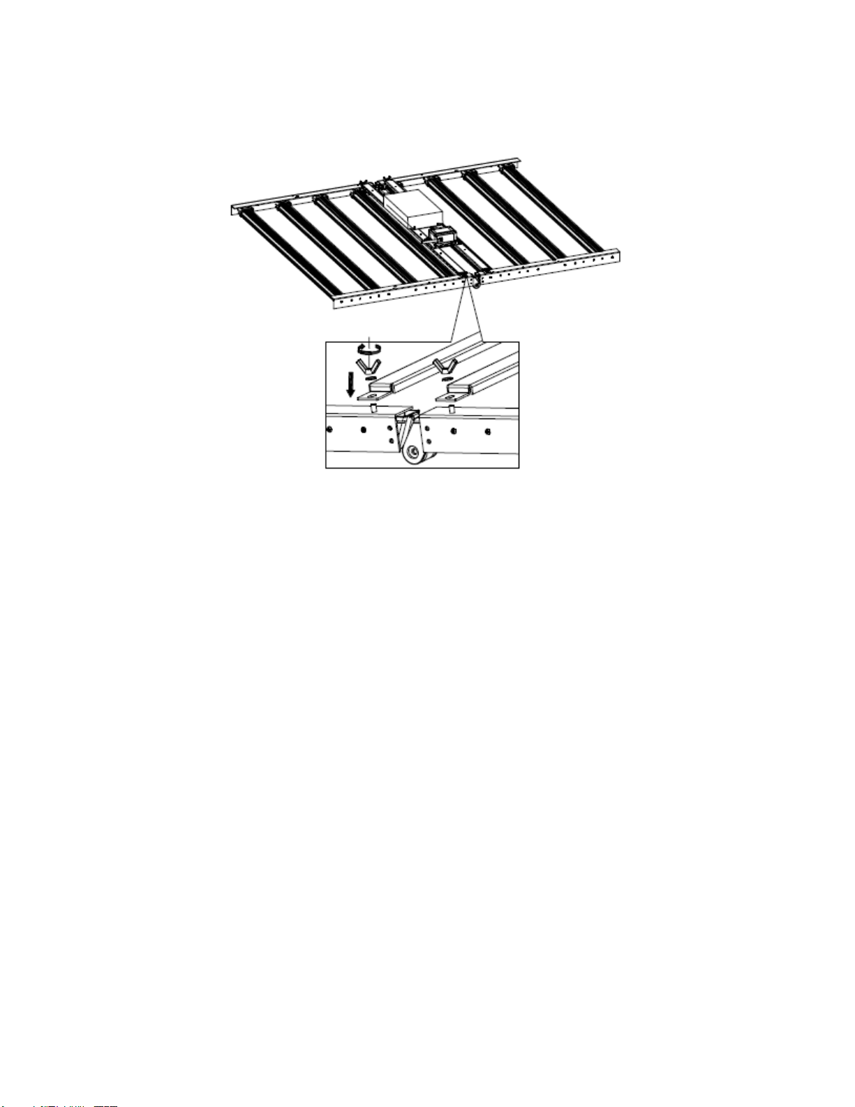
Your FGI Uniformity Pro ships partially constructed and folded (A) to reduce the expense of shipping
and protect the components in the light.
Illustration A
Take care when unpacking and handling the light fixture. Unpack gently and avoid pinching your fingers
when you fold the unit open.
Ensure the LED arrays do not come in contact with sharp objects or force that may damage the diodes.
The Uniformity Pro is ruggedly built but it can be damaged with rough handling.
Unbox and unfold module (B) and place on flush on a floor or a clear open table surface, cardboard or
plastic is recommended to be placed between the units lens and the surface you are working on to avoid
scratching the lens.
Illustration B
DO NOT POWER UP THE LIGHT UNTIL IT IS FULLY ASSEMBLED AND HUNG OVER THE
GROW AREA.
Mounting the Power Supply:

5
Mount the power supply by attaching the four wing nuts and washers to the screws protruding on the light
frame (C). Tighten securely but do not over tighten the nuts.
Illustration C
Place power supply enclosure on top of brackets, aligning the bracket mounts with the receivers. The snap
connector wiring connections are universal however they are slightly different lengths. Ensure the power
supply is aligned with the snap connector that easily connects to both ends without pulling or stretching
the cables.

6
Connecting the power to the power supply:
Next connect the power supply to both snap connectors on each side (D). Simply plug in and twist the
connection closed. This helps ensure the fixture is water resistant.
Illustration D
Once the power supply enclosure is installed, do not attempt to fold the Uniformity Pro. Doing so will
cause significant damage to the fixture. The power supply housing holds the Uniformity Pro in a rigid
open position.
Next connect the power cord to the remaining snap connector. Install the power plug of your choice. The
unit can be wired for 110V-277V power using an appropriate plug for the power receptacle being used.

7
Attaching the hanging snap connectors:
We supply four cable connectors which attach to holes in the top of the frame (E) and these can be used
together with supplied cable hangars, rope hangars or other hanging hardware to suspend your Uniformity
Pro over the grow area. Use hanging hardware suitable for the weight of the fixture to avoid having the
unit slip and fall.
Illustration E

8
Light to Light T connector (daisy chain) for Controller/Dimmer Accessories
FGI Uniformity Pro models are available with the optional FGI controllers. Each light is pre-wired to
allow connection of the controller, and also pre-wired to allow daisy chaining the units to one another. (F)
Illustration F
Maximum number of lights per daisy chain: recommended 20 units. Not more than 60’ (20 meters) of
total distance from the first unit to the last unit.
Capping/watertight cover
Each unit comes with one cap to be used to cover the final connector which will be unused in the daisy
chain. Please keep this cap in place to improve water resistance. (G)
Illustration G

9
Installation Distance:
The FGI Uniformity Pro is designed for ideal light uniformity on the plant canopy. The units should be
mounted so that the bars on adjacent units are within the same distance as the bars on the light itself, 50
MM or about 2” between each frame (G).
Illustration G
Actual mounting distances are optional however this is the ideal distance to cover 4’x4’ areas adjacent to
one another.
Installation Height:
Mounting heights above plant canopy are variable based on the plant being grown and the phase / age of
the plant. We recommend the use of a PAR meter that measures full spectrum 380-700nm.
For flowering/reproduction phase the light should be mounted to provide 900 umols of PAR. A single
Uniformity Pro will produce 900 umols of PAR at 12”. Multiple lights will increase this level.
For vegetative phase the light should be mounted to provide 450 umols of PAR. A single light will
produce 450 umols at 24”-30” from canopy.

10
FGI UNIFORMITY PRO EXTENDED FEATURES
Depending on the model you have purchased the Uniformity Pro can be used without dimming, or with
an optional 1-10V dimmer or controllers available from FGI.
Non-dimming:
The FGI Uniformity Pro can be used without dimming. The unit is designed to produce very uniform and
even PAR distribution depending on the height it is hung from the canopy. Moving the light further away
from the top of the canopy serves to reduce light intensity and also has the effect of increasing uniformity
of light. If your grow area has “head room” above the light fixture, it is not necessary to use dimming
controller to reduce light intensity. Simply raise the light higher to reduce PAR on the plant canopy. A
high quality PAR meter designed to measure full-spectrum LED is recommended.
Bluetooth Mesh (optional):
Please see the separate product manual for the Bluetooth mesh controller.
Dimming Controller (optional)
Please see the separate product manual for the Bluetooth mesh controller.

11
WARRANTY
FGI is committed to manufacturing and distributing the highest quality products with the highest level of
workmanship in the marketplace. We provide a limited 5 year warranty for the FGI Uniformity Pro
against defects in manufacturing. Please see our website for a full explanation of our warranty terms and
conditions.

12
Troubleshooting
Your new Uniformity Pro was designed and built using the highest quality components and electrical
design. Unfortunately however, in rare instances, the unit may suffer a malfunction. In the case that the
light does not turn on as expected, or, in the case of the Uniformity Pro 640 only half the bars light up, it
is likely that there is a wire connection which has come loose. Here are instructions for how to
troubleshoot a malfunctioning lights. NOTE: It is highly unusual for the Inventronics EUD-600S driver to
malfunction or to stop working, if used within standard operating conditions (indoor and greenhouse
facilities, 12-14 hours of use per day continuous use for a minimum of 5 years from date of purchase). We
encourage you to not suspect the driver is the problem. In all cases we have determined it is a wiring fault
and not the driver itself. The driver has built in protection and in the case of a mis-wiring or short it will
simply turn itself off until the wiring issue is resolved.
Troubleshooting tips:
Symptom
Likely Cause
Solution / Fix
The light does not
come on when
connected to
power
There are a few possible
causes for this condition. In
all cases it is in the wiring
connections either between
the driver and the LED bars
(there are two wires that
split from an IP-68 T
shaped wiring splice which
leads to 4 sets of bars on
each end.)
Before you begin, make sure that the twist
connectors are correctly seated and tight. NEVER
FORCE THE CONNECTORS TOGETHER. If the
screw connection is difficult twist the outer screw
connection to free up the threads. Make sure you
look for two wire (low voltage power to bars)
versus three wire (wall input power). Connect
snugly and twist the connectors to lock the
connection securely. Plug the light back in and
power it up. If it still not working follow the steps
here based on the symptoms.
#1 Turn off power to the light and unplug from the
wall.
#2 Identify the larger T shaped IP-68 wire splice
coming out of the driver. It is typically 8-10”from
the driver itself. This wire is the low voltage power
output and send power to the bars through the
splice to two wires that lead to each side of the
light. In earlier versions of the light this connector
has yellow washers or bands that make the
connection water tight. In later versions the bands
are black.
#3 Begin by unscrewing the outer cap (wire
tensioner) of the wire that leads from the driver to
the connector.
#4 Next unscrew the inner cap (connection
protector) of this same connection. Note that on the
T connector there are three outer caps which screw
on to the three inner caps.

13
#5 Gently pull the outer cap and then the inner cap
down the wire to allow inspection of the wire
connection to the T connector.
#6 Inspect the two wires (one blue- and one red+)
as they lead into the two sockets and the two
screws that create a tight connection. In earlier
models this T connector uses black tabs and not
screws to tighten the connection. If you have the
tab version, it may be difficult to remove the epoxy
and re-use the connector. (FGI will ship you, at no
cost, a new T connector with screw terminals if
you prefer. Contact us at
shop@forevergreenindoors.com to receive yours).
#7 Gently pry or chip off the epoxy using plyers to
allow access to inspect the connection.
#8 Use a small Philips screw driver to unscrew the
two terminals (this may make removing the epoxy
easier).
STOP –If the connector for any reason is unusable
after this process (for example if the screw
becomes stripped or you are unable to free the
wires and clear all the epoxy, contact Forever
Green Indoors for a free connector so you can
complete this task.)
shop@forevergreenindoors.com
#9 Gently remove the Blue- and Red+ wires from
the sockets. IMPORTANT: Before you remove
note the polarity indication on the surface of the
connector. They are very small. L is the load or
Red+ and N is the neutral or Blue-.
#10 Measure the length of the stripped bare wire. It
must be 10MM or 3/8”long to properly seat in the
socket and allow the screw down terminal to
tightly secure the wire.
#11 Trim and re-strip the wire to 10MM or 3/8”, as
necessary.
#12 Back out the screws to allow a clear channel to
insert the stripped wires. Insert the wire into the
proper polarity hole and tighten down securely
using the screw or tabs. DO NOT INSERT
BEYOND THE STRIPPED WIRE. If the plastic
wire sheath is trapped in the channel it may cause a
faulty connection.
#13 Gently move the inner cap back to the threads.
Ensure that the cable does not twist while you
tighten the inner cap.
#14 Gently move the outer wire tensioner cap
down to the threads. Ensure the cable does not

14
twist while you tighten the outer cap and that the
wire in snugly secure in the tensioner.
#15 Plug the light back in to the power source and
power up the light.
IF THE LIGHT FAILS TO COME ON THEN
MOVE TO STEP TWO
The light does not
come on when
connected to
power
The second possible cause
for this condition is a
shorted wire between the
driver and the T shaped
dimming daisy chain wiring
module. (This can be
identified as the smaller IP-
68 T shaped wiring splice
coming from the driver
which leads to plugs to
allow the lights to be daisy
chained for dimming
control). Regardless of
whether or not you have a
controller connected or just
a single light with no
dimming cable connected,
this T shaped wiring
connector should be
checked.
Before you begin, make sure that the twist
connectors are correctly seated and tight. NEVER
FORCE THE CONNECTORS TOGETHER. If the
screw connection is difficult twist the outer screw
connection to free up the threads. Make sure you
look for two wire (low voltage power to bars)
versus three wire (wall input power). Connect
snugly and twist the connectors to lock the
connection securely. Plug the light back in and
power it up. If it still not working follow the steps
here based on the symptoms.
#1 Turn off power to the light and unplug from the
wall.
#2 Identify the T shaped IP-68 wire splice coming
out of the driver. It is typically 8-10”from the
driver itself.
STOP –Determine the version of the light you are
working on. Early versions used a large T
connector that looks identical to the low voltage
power output described above, except that, unless a
dimming cable was attached to allow daisy chain
control of the lights, this plug will have two ends
with no wiring extending out. Newer versions of
the UP 640 have a smaller black IP-68 T shaped
wire adapter.
#3 Begin by unscrewing the outer cap (wire
tensioner) of the wire that leads from the driver to
the connector.
#4 Next unscrew the inner cap (connection
protector) of this same connection.
#5 Gently pull the outer cap and then the inner cap
down the wire to allow inspection of the wire
connection to the T connector.
#6 Inspect the two wires (one grey Dim- and one
purple Dim+) as they lead into the two sockets and
the two screws that create a tight connection. It is
very important that the bare wires do not cross or
touch each other. If you notice the wires are

15
twisted and are touching one another this is the
problem which is causing the light to malfunction.
#7 Use a small Philips screw driver to unscrew the
two terminals.
#9 Gently remove the wires from the sockets.
IMPORTANT: Before you remove note the
polarity indication on the side of the connector next
to the Phillips head screw. They are very small. L
is the load or purple Dim + and N is the neutral or
grey Dim-
#10 Measure the length of the stripped bare wire. It
must be no more than 6MM or 1/4”long to
properly seat in the socket and allow the screw
down terminal to tightly secure the wire.
#11 Trim and re-strip the wire as necessary. If you
must remove the outer wire bundle insulation make
sure that the distance between the end of the
insulation and the tip of the wire is no more than
25mm or 1”to allow the outer screw to properly
tension the outer wire bundle insulation. It is very
important that the outer cap seats snugly on the
wire to ensure the connection is water tight and
that it won’t be accidentally yanked out in the
future.
#12 Back out the screws to allow a clear channel to
insert the stripped wires. Insert the wire into the
proper polarity hole and tighten down securely
using the screw. DO NOT INSERT BEYOND
THE STRIPPED WIRE. If the plastic wire sheath
is trapped in the channel it may cause a faulty
connection.
#13 Gently move the inner cap back to the threads.
Ensure that the cable does not twist while you
tighten the inner cap.
#14 Gently move the outer wire tensioner cap
down to the threads. Ensure the cable does not
twist while you tighten the outer cap and that the
wire in snugly secure in the tensioner.
#15 Plug the light back in to the power source and
power up the light.
Only half of the
bars light up (4 on
4 off)
This is caused by a loose
connection in the T
connector which feeds the
low voltage power to each
set of 4 bars.
Before you begin, make sure that the twist
connectors are correctly seated and tight. NEVER
FORCE THE CONNECTORS TOGETHER. If the
screw connection is difficult twist the outer screw
connection to free up the threads. Make sure you
look for two wire (low voltage power to bars)
versus three wire (wall input power). Connect
snugly and twist the connectors to lock the
connection securely. Plug the light back in and

16
power it up. If it still not working follow the steps
here based on the symptoms.
Next, note which 4 bars are not working and follow
the wire back to the T connector. This is the
connection you will be troubleshooting.
#1 Turn off power to the light and unplug from the
wall.
#2 Identify the larger T shaped IP-68 wire splice
coming out of the driver. It is typically 8-10”from
the driver itself. This wire is the low voltage power
output and send power to the bars through the
splice to two wires that lead to each side of the
light. In earlier versions of the light this connector
has yellow washers or bands that make the
connection water tight. In later versions the bands
are black.
#3 Begin by unscrewing the outer cap (wire
tensioner) of the wire previously identified, which
leads from the T connector to the four bars which
are not working.
#4 Next unscrew the inner cap (connection
protector) of this same connection. Note that on the
T connector there are three outer caps which screw
on to the three inner caps.
#5 Gently pull the outer cap and then the inner cap
down the wire to allow inspection of the wire
connection to the T connector.
#6 Inspect the two wires (one white+ and one
black-) as they lead into the two sockets and the
two screws that create a tight connection. In earlier
models this T connector uses black tabs and not
screws to tighten the connection. If you have the
tab version, it may be difficult to remove the epoxy
and re-use the connector. (FGI will ship you, at no
cost, a new T connector with screw terminals if
you prefer. Contact us at
shop@forevergreenindoors.com to receive yours).
#7 Gently pry or chip off the epoxy using plyers to
allow access to inspect the connection.
#8 Use a small Philips screw driver to unscrew the
two terminals (this may make removing the epoxy
easier).
STOP –If the connector for any reason is unusable
after this process (for example if the screw
becomes stripped or you are unable to free the
wires and clear all the epoxy, contact Forever
Green Indoors for a free connector so you can

17
complete this task.)
shop@forevergreenindoors.com
#9 Gently remove the black- and white+ wires
from the sockets. IMPORTANT: Before you
remove note the polarity indication on the surface
of the connector. They are very small. L is the load
or white+ and N is the neutral or black-.
#10 Measure the length of the stripped bare wire. It
must be 10MM or 3/8”long to properly seat in the
socket and allow the screw down terminal to
tightly secure the wire.
#11 Trim and re-strip the wire to 10MM or 3/8”, as
necessary.
#12 Back out the screws to allow a clear channel to
insert the stripped wires. Insert the wire into the
proper polarity hole and tighten down securely
using the screw or tabs. DO NOT INSERT
BEYOND THE STRIPPED WIRE. If the plastic
wire sheath is trapped in the channel it may cause a
faulty connection.
#13 Gently move the inner cap back to the threads.
Ensure that the cable does not twist while you
tighten the inner cap.
#14 Gently move the outer wire tensioner cap
down to the threads. Ensure the cable does not
twist while you tighten the outer cap and that the
wire in snugly secure in the tensioner.
#15 Plug the light back in to the power source and
power up the light.
Table of contents
Other Forever Green Indoors Lighting Equipment manuals
Popular Lighting Equipment manuals by other brands

KLS Martin
KLS Martin independant Fix Bridge Instructions for use

Quarkpro Light
Quarkpro Light PULSAR user manual

Aqua Creek Products
Aqua Creek Products MIGHTY 400-BLUE manual

venalsol
venalsol 50W instructions

Red Arrow
Red Arrow ANA/30 installation instructions

Eaton
Eaton ephesus Arena Series installation instructions