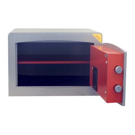
Format S1 Service manual

BEDIENUNGS- UND MONTAGEANLEITUNG
Sicherheitsschränke S1 nach EN 14450
Bitte vor Erst-Inbetriebnahme
unbedingt lesen!
Please read
before initial operation!
Veuillez lire attentivement
ces instructions avant la première
utilisation!
DE S.2
EN S.7
OPERATING AND MOUNTING INSTRUCTIONS
S1 Safes according to EN 14450
INSTRUCTIONS D’UTILISATION ET DE MONTAGE
Armoires de sécurité S1 selon EN 14450 FR S.11

2
DE
BEDIENUNGS- UND MONTAGEANLEITUNG
FORMAT Sicherheitsschränke S1 nach EN 14450
Inhalt
1. Herstelleranweisung zum sicheren Betrieb
2. Bedienung
3. Verankerung und Montage
4. Haftungsbegrenzung/ErlöschenderZertizierung
5. Wartung und Service
6. Entsorgung
Sie haben sich beim Tresorkauf für ein Qualitätsprodukt mit geprüfter Sicherheit
entschieden. Diese Anleitung beschreibt Ihnen die Bedienung und Montage Ihres Tresors.
Bitte lesen Sie vor Inbetriebnahme Ihres Tresors diese Anleitung genau durch und
bewahren Sie diese gut auf!
Geltungsbereich der Anleitung:
Sicherheitsschränke der Sicherheitsstufe S1 nach EN 14450
Das Typenschild (Plakette) mit Angabe der Modellbezeichnung (Serial No.), der Sicherheits-
klasse (Security level) und der Zertizierungsnummer (Cert. mark No.) bendet sich im
oberen Bereich auf der Türinnenseite. Bitte geben Sie bei Rückfragen diese Daten an.
Falls Sie den Inhalt Ihres Tresors versichern wollen, klären Sie bitte die genaue
Versicherungssumme mit Ihrem Sachversicherer ab.
1. HERSTELLERANWEISUNG ZUM SICHEREN BETRIEB
• Vor der Erst-Inbetriebnahme (Öffnen der Tresortür) bitte unbedingt darauf achten, dass
der Tresor korrekt aufgestellt ist. Zusätzlich ist der Tresor gegen Kippen zu sichern.
• Beim Schließen der Tresortür unbedingt darauf achten, dass sich keine Gliedmaßen
zwischen Tresortür und Tresorrumpf benden. Es besteht sonst die Gefahr von
Quetschungen.
• Vor dem Schließen der Tresortür unbedingt sicherstellen, dass die Riegelbolzen in der
Tresortür eingefahren sind. Ausgefahrene Riegelbolzen stoßen beim Schließen der Tür
gegen den Tresorrumpf und führen zu Beschädigungen und Fehlfunktionen der Verrie-
gelung.
• Manipulationssicherung: Zur Verhinderung von unbemerkter Manipulation ist das
Abdeckblech für den Verschlussmechanismus mit einem Siegel ausgestattet.
WARNUNG! LEBENSGEFAHR!
Bei Verpackungs- und Schutzfolien besteht Erstickungsgefahr.
Halten Sie Verpackungs- und Schutzfolien von Kindern fern.
2. BEDIENUNG
2.1 Öffnen der Tür
Tresore mit einem Doppelbart-Schlüsselschloss: (Türanschlag rechts)
Schlüssel einführen und bis zum Anschlag im Uhrzeigersinn nach rechts drehen, danach den
Türgriff ebenfalls im Uhrzeigersinn ganz nach rechts drehen und die Tür aufziehen.
Bei Tresoren mit Türanschlag links muss der Türgriff beim Öffnen nach links gegen den
Uhrzeigersinn gedreht werden.
Bitte beachten Sie, dass Doppelbart-Schlüssel zwei unterschiedliche Seiten
(Bärte) haben. Beim Einführen des Schlüssels in das Schlüsselloch muss die längere Seite
in Richtung des Türgriffs zeigen.

3
DE
BEDIENUNGS- UND MONTAGEANLEITUNG
FORMAT Sicherheitsschränke S1 nach EN 14450
Tresore mit einem mechanischen Zahlenschloss:
Dem mechanischen Zahlenschloss liegt eine eigene Bedienungsanleitung bei.
Wichtig: Bitte ändern Sie den voreingestellten Werkscode und ersetzen diesen durch einen
persönlichenCode.
Zum Umstellen des Werkscodes bendet sich eine Bohrung im Türverkleidungsblech auf
Höhe des Schlosses, bitte die Abdeckkappe über der Bohrung entfernen und den Umstell-
schlüssel in das Zahlenschloss einführen.
Das Türverkleidungsblech muss dafür nicht demontiert werden!
2.2 Schließen der Tür
Tresore mit einem Doppelbart-Schlüsselschloss: (Türanschlag rechts)
Tür fest zudrücken, Türgriff gegen den Uhrzeigersinn ganz nach links drehen und den
Schlüssel ebenfalls gegen den Uhrzeigersinn nach links drehen. Nun den Schlüssel aus der
Tür heraus ziehen.
Bei Tresoren mit Türanschlag Links muss der Türgriff beim Schließen im Uhrzeigersinn nach
rechts gedreht werden.
Wichtig: Vergewissern Sie sich, dass die Tür ordnungsgemäß versperrt ist.
Wichtig:IhrTresoristmiteinemzertiziertenDoppelbart-Schlüsselschlossmit„Schließ-
zwang” ausgestattet.
Der Schlüssel kann nur abgezogen werden, wenn das Schloss versperrt ist.
SCHLÜSSELVERLUST: (nur bei Ausführung Doppelbart-Schlüsselschloss)
Serienmäßig erhalten Sie 2 Doppelbartschlüssel. Bei Verlust eines oder mehrerer
Schlüssel muss das Schloss aus Sicherheitsgründen ausgetauscht werden, da sonst der
Versicherungsschutz erlischt. Sollten Sie einen zusätzlichen Schlüssel benötigen, verfahren
SieentsprechenddesbeigelegtenFormblattes„Schlüssel-Bestellung”.
Zusatzschlüssel können generell aus Sicherheitsgründen nur nach Vorlage eines Original-
schlüssels angefertigt werden.
Bewahren Sie Ihre Schlüssel sorgfältig auf, bei Verlust muss der Tresor von einem Service-
techniker gewaltsam geöffnet werden.
3. VERANKERUNG UND MONTAGE
3.1 Allgemeines
Wenn Sie den Inhalt (Sachwerte) Ihres Tresors versichern wollen, ist die fachgerechte Be-
festigung Ihres Tresors bei einem Eigengewicht unter 1000 kg eine Mindestanforderung
gemäß der Europäischen Zertizierungsnorm EN 14450. Stimmen Sie die Rahmenbedin-
gungen zum Aufstellort und zur Verankerung mit Ihrem Sachversicherer ab.
Der Tresor erreicht seine optimale Schutzfunktion erst nach Befestigung an einem massiven
Gebäudeteil. Bitte verwenden Sie nur die vorgesehenen Verankerungsbohrungen im Tresor,
um die notwendige ortsfeste Verbindung herzustellen. Serienmäßig ist Ihr Tresor mit min-
destens zwei Verankerungsbohrungen im Boden oder an der Rückwand versehen. Je nach
Modell kann Ihr Tresor auch mit weiteren Verankerungsbohrungen versehen sein.

4
BEDIENUNGS- UND MONTAGEANLEITUNG
FORMAT Sicherheitsschränke S1 nach EN 14450
DE
Die fachgerechte Verankerung muss immer durch mindestens zwei Verankerungs-
bohrungen erfolgen. Dem Tresor liegt standardmäßig entsprechendes Verankerungs-
material bei.
2 Stück Dübel M12S für metrische Schrauben M12
2 Stück Sechskantschraube DIN 933 M12 x 100-Festigkeitsklasse 8.8
2 Stück Scheibe DIN 125 D=24 / 13 x 2,5 mm
Sollte das mitgelieferte Befestigungsmaterial - aufgrund der Untergrundbeschaf-
fenheit - nicht zu verwenden sein, muss das Befestigungsmaterial kundenseitig
den Gegebenheiten des Untergrundes angepasst werden.
Das Befestigungsmaterial muss dabei jedoch folgenden Anforderungen entsprechen:
Dübel:
Der mitgelieferte Spreizdübel M12S ist geeignet für tragende Untergründe aus Beton, Po-
renbeton, Vollziegel oder Kalksand-Vollstein.
Wichtig:
Stellen Sie vor der Verankerung unbedingt sicher, dass der Untergrund für das mitgelieferte
Befestigungsmaterial geeignet ist und sich im Bohrbereich keine Kabel, Leitungen, Rohre
oderähnlichesbenden.AndernfallsmusseineandereBefestigungsartund/oderBefesti-
gungsort gewählt werden.
3.2 Verankern mit dem beiliegendem Montagematerial
Den Tresor am vorgesehenen Standort aufstellen und in Waage ausrichten. Markieren Sie
die Bohrposition im zu verankernden Bereich durch die Verankerungsbohrungen im Tresor
hindurch und entfernen Sie den Tresor dann wieder vom Bohrbereich.
Bohren Sie mit einem Steinbohrer (Ø 16 mm) mindestens 100 mm tief in den Untergrund.
Säubern Sie nun das Bohrloch (Bohrstaub aussaugen)[1].
Schlagen Sie den Dübel in das Bohrloch [2] und bringen Sie den Tresor wieder in die end-
gültige Position. Verschrauben Sie nun den Tresor mit der Schraube M12 und der Unterleg-
scheibe. Zum leichteren Eindrehen der Schraube oder Gewindestange kann das Gewinde
leicht angefast werden [3].
Bei Einbruch / Diebstahl haftet Ihr Versicherer nicht für Sach- oder Vermögensschäden bei
unsachgemäßer Verankerung.
Verankerungs-Schraube oder
Gewindestange:
Gewinde M12 / Festigkeitsklasse 8.8
Sechskantmutter DIN/ISO 934: Gewinde M12 / Festigkeitsklasse 8.8
Unterlegscheibe DIN/ISO 125: Innendurchmesser 13 mm / Außendurchmesser
24 mm / Dicke 2.5 mm

5
DE
BEDIENUNGS- UND MONTAGEANLEITUNG
FORMAT Sicherheitsschränke S1 nach EN 14450
Achtung:
Bitte beachten Sie, dass - abhängig vom Boden- bzw. Wandaufbau - spezielle Dübel die
Wirksamkeit der Verankerung weiter erhöhen können.
Die Spreizlänge des Dübels muss sich immer im festen Untergrund (Beton oder Mauerwerk)
benden.
Bei schwimmendem Estrich als Untergrund empfehlen wir, die Bohrtiefe um die Höhe des
schwimmendenEstrichsinkl.derdarunterbendlichenIsolierungzuerhöhen.Verwenden
Sie dann in diesem Fall entsprechend längere Schrauben mit M12 Gewinde und einer Fes-
tigkeit von mindestens 8.8.
4. HAFTUNGSBEGRENZUNG / ERLÖSCHEN DER ZERTIFIZIERUNG
Bedingt durch Folgeschäden nach Einbruchsversuchen, Bränden, sowie unsachgemäßen
Eingriffen in die Konstruktion und Funktion des Tresors erlöscht die Gültigkeit der Zer-
tizierung und die Gewährleistung. Die FORMAT Tresorbau GmbH & Co. KG haftet nicht
für Funktionsstörungen, bedingt durch Gewaltanwendung oder unsachgemäßer Behand-
lung und nicht bei Sach- oder Vermögensschäden, die z. B. auf das nicht ordnungsgemäße
Verschließen des Tresors zurückzuführen sind. Bei Funktionsstörungen dürfen Reparaturen
ausschließlich durch vom Hersteller autorisierte Firmen vorgenommen werden.
5. WARTUNG UND SERVICE
Das Riegelwerk und das Schloss sind wartungsfrei.
Sollten Störungen auftreten, die Sie nicht selbst beheben können, oder Sie weitere Fragen
haben, wenden Sie sich bitte an Ihren Tresorhändler oder direkt an den Hersteller Ihres
Tresors:
FORMATTresorbauGmbH&Co.KG
Industriestraße 10-24
D-37235 Hessisch Lichtenau
Tel. +495602 / 939 888
www.format-tresorbau.de
1) Bohrposition
markieren und bohren (Ø
16 mm, mind.
100 mm tief)
2) Bohrloch säubern und
Dübel einschlagen 3)Tresor positionieren
und Schraube M12 mit
U-Scheibe eindrehen

6
BEDIENUNGS- UND MONTAGEANLEITUNG
Sicherheitsschränke S1 nach EN 14450
6. ENTSORGUNG
Sollten Sie zu einem Zeitpunkt beabsichtigen, Ihren Tresor zu entsorgen, denken Sie bitte
daran, dass viele Bestandteile dieses Tresors aus wertvollen Materialien bestehen, welche
recycelt werden können.
Batterien oder Akkus mit diesem gekennzeichneten Symbol enthalten
Schadstoffe.
Konformitätserklärung: Mit diesem Symbol gekennzeichnete Produkte erfüllen
alle anzuwendenden Gemeinschaftsvorschriften des Europäischen Wirtschafts
raums.
Entsorgen Sie die Verpackung sortenrein. Auskünfte zur Entsorgung erhalten
Sie auch bei Ihrer kommunalen Stelle.
Irrtum und Änderungen vorbehalten.
DE

7
EN
OPERATING AND MOUNTING INSTRUCTIONS
S1 Safes according to EN 14450
Contents
1. Manufacturer’s instructions for safe operation
2. Operation
3. Anchoring and assembly
4. Limitationofliability/certicationexpiry
5. Maintenance and Service
6. Disposal
Bybuyingthissafe,youhavechosenaqualityproductwithcertiedsecurity.Thismanual
describes how to operate and install your safe.
Please read this manual carefully before using your safe and keep it in a safe
place!
Scope of the manual:
Security level S1 according to EN 14450
Thetypeplate(certicationtag)withthemodelname(serialno.),thesecurityclass(secu-
ritylevel)andthecerticationnumber(cert.markno.)islocatedintheupperareaonthe
inside of the door. Please specify this information if you have any questions.
If you want to insure the contents of your safe, please clarify the exact sum insured with
your property insurer.
1. MANUFACTURER’S INSTRUCTIONS FOR SAFE OPERATION
• Before initial use (opening the safe door), make sure that the safe has been set up
correctly. The safe must also be secured against tipping.
• When closing the safe door, make sure that there are no limbs between the safe door
and the safe body. Otherwise, there is a risk of injuries due to limbs becoming trapped.
• Before closing the safe door, you must make sure that the locking bolts in the safe
door are retracted. When closing the door, extended latch bolts knock against the vault,
damage the latch and cause it to malfunction.
• Security against tampering: To prevent unseen tampering, the cover plate for the locking
mechanism is provided with a seal.
WARNING! RISK TO LIFE!
Packaging and protective lms may cause suffocation. Keep packaging and
protectivelmsawayfromchildren.
2. OPERATION
2.1 Opening the door
Safes with a double bit key lock: (Right door hinge)
Insert the key and turn clockwise to the right until it stops, then fully turn the handle clock-
wise to the right, and pull the door open.
For safes with door hinges on the left, the door handle must be turned anti-clockwise when
opening to the left.
Please note that double bit keys have two different sides (bits). When inserting the key into
the keyhole, the longer side must point towards the door handle.
Safes with an electronic code lock:
The electronic code lock comes with its own seperate manual.
Important: Please change the default factory code and replace it with your own code.

8
EN
OPERATING AND MOUNTING INSTRUCTIONS
S1 Safes according to EN 14450
Safes with a mechanical combination lock:
The mechanical combination lock comes with its own seperate manual.
Important: Please change the default factory code and replace it with your own code.
To change the factory code, there is a hole in the door trim panel at lock level, please remo-
ve the cover over the hole and insert the change key into the combination lock.
The door trim panel does not have to be dismantled!
2.2 Closing the door
Safes with a double bit key lock: (Right door hinge)
Pressthedoorrmlyshut,turnthedoorhandleanti-clockwisefullytotheleftandturnthe
key anti-clockwise to the left. Now pull the key out of the door.
For safes with door hinges on the left, the door handle must be turned clockwise when
closing to the right.
Important: Make sure the door is locked properly.
Important: Yoursafeisttedwithacertieddoublebitkeylockanda„aforcedlocking
key”. The key can only be removed if the lock is blocked.
Key loss: (for double bit key design only)
You will receive 2 double bit keys as standard. If one or more keys are lost, the lock must
be replaced for security reasons, otherwise the insurance cover will be voided. If you need
anadditionalkey,proceedasperthe„keyorder”formenclosed.
For security reasons, additional keys can generally only be made after an original key has
been presented.
Keep your keys in a safe place; in the event of loss, the vault must be opened by a service
technician.
3. ANCHORING AND ASSEMBLY
3.1 GENERAL
If you want to insure the contents of your safe, proper fastening of your safe with a dead
weightoflessthan1000kgisaminimumrequirementaccordingtotheEuropeancerti-
cation standard EN 14450. Agree on the conditions for installation and anchoring with your
property insurer.
Thesafecanonlyprovidemaximumprotectionafteritisxedtoasolidpartofthebuilding.
Please only use the anchoring holes provided in the vault to make the required xed
connection.Yoursafeisttedwithatleasttwoanchoringholesintheoororontherear
wall as standard. Depending on the model, your safe may also be provided with additional
anchoring holes.
Proper anchoring always has to be done with at least two anchorage holes. Appropriate
anchoring material is enclosed with the safe as standard.
2 x dowel M12S for metric screws M12
2 x hex screw DIN 933 M12x100 strength class 8.8
2 x washer DIN 125 D = 24 / 13 x 2.5 mm
If the supplied fastening material - due to the nature of the substrate - cannot be
used, the fastening material must be adapted to the conditions of the substrate
by client himself.

9
EN
OPERATING AND MOUNTING INSTRUCTIONS
S1 Safes according to EN 14450
1) Mark drilling
position and drill
(Ø16 mm, at least 100
mm deep)
2)Cleanthedrillhole
and hammer in the
dowels
3) Position the safe
and insert screw M12
with U-washer
Anchor bolt or threaded rod: Thread M12 / strength class 8.8
Hexagon nut DIN / ISO 934: Thread M12 / strength class 8.8
Washer DIN / ISO 125: Internal diameter 13 mm / external diameter 24 mm
/ thickness 2.5 mm
However, the fastening material must meet the following requirements:
Dowel:
The expansion dowel M12S provided is suitable for load-bearing surfaces made of concrete,
aerated concrete, solid brick or sand-lime bricks.
Important:
Beforeanchoringit,makeabsolutelycertainthatthesuboorissuitableforthefastening
material provided, and that there are no cables, lines, pipes or the like in the drilling area.
Otherwise, another type and / or place of fastening must be selected.
3.2 ANCHORING WITH THE ENCLOSED FITTING MATERIAL
Set up the vault at the intended location and align it so it is in balance. Mark the drilling po-
sition in the area to be anchored through the anchoring holes in the vault, and then remove
the vault again from the drilling area.
Drill a minimum depth of 100 mm into the substrate using a Ø 16 mm stone drill. Now clean
the borehole (extract drilling dust) [1].
Insertthedowelintothehole[2]andreturnthevaulttoitsnalposition.Nowboltthesafe
with the screw M12 and the washer. The thread can be easily chamfered so it is easier to
insert the screw or threaded rod [3].
In the event of break-in / theft, your insurer will not be liable for property damage or
pecuniary damage if improperly anchored.

10
Caution:
Pleasenotethat-dependingontheoororwallconstruction-specialdowelscanfurther
increase anchorage effectiveness.
The dowel’s expansion length must always be in solid ground (concrete or masonry).
Foroatingscreedassubstrate,werecommendincreasingthedrillingdepthbytheheight
oftheoatingscreedincludingtheinsulationunderneath.Inthiscase,uselongerscrews
accordingly with M12 thread and a strength of at least 8.8.
4. LIMITATION OF LIABILITY / CERTIFICATION EXPIRY
Ifthereisconsequentialdamageafterburglaryattempts,resorimproperinterventionsin
theconstructionandfunctionofthevault,thevalidityofthecerticationandwarrantyshall
expire.FORMATTresorbauGmbH&Co.KGisnotliableformalfunctionscausedbytheuseof
force or improper handling, and not in the event of damage to property or pecuniary loss. e.g.
due to improper closure of the vault. In the event of malfunctions, repairs may only be carried
out by companies authorised by the manufacturer.
5. MAINTENANCE AND SERVICE
The locking mechanism and the lock are maintenance-free.
If you encounter problems that you can not resolve yourself, or if you have any more ques-
tions, please contact your vendor or your safe’s manufacturer directly:
FORMATTresorbauGmbH&Co.KG
Industriestraße 10-24
D-37235 Hessisch Lichtenau
Tel. +495602 / 939 888
www.format-tresorbau.de
6. DISPOSAL
If at any time you intend to dispose of your safe, remember that many parts of this safe are
made of valuable materials that can be recycled.
Batteries marked with this symbol contain harmful substances.
DeclarationofConformity:Productsmarkedwiththissymbolcomplywithall
applicable community Legislation of the European Economic Area.
Dispose of the packaging by sorting it correctly. Information about disposal
can also be obtained from your local authority.
Errors and changes excepted.
EN
OPERATING AND MOUNTING INSTRUCTIONS
S1 Safes according to EN 14450

11
FR
INSTRUCTIONS D’UTILISATION ET DE MONTAGE
Armoires de sécurité S1 selon EN 14450
Contenu
1. Instructions du fabricant pour une utilisation en toute sécurité
2. Utilisation
3. Ancrage et montage
4. Limitationderesponsabilité/Annulationdelacertication
5. Entretien et maintenance
6. Mise au rebut
Enachetantuncoffre-fort,vousavezchoisiunproduitdequalitéetd’uneabilitééprouvée.
Cemanueldécritlefonctionnementetl’installationdevotrecoffre-fort.
Veuillez lire attentivement ces instructions avant d’utiliser votre coffre-fort et
conservez-les bien!
Plage de validité du manuel:
Armoires de sécurité de classe S1 selon EN 14450
La plaque signalétique (plaquette) avec le nom du modèle (n° de série), la classe de sé-
curité(Security level)et lenuméro decertication (Cert.markNo.)se trouveen partie
supérieure à l’intérieur de la porte. Merci de fournir ces informations pour toute question
supplémentaire.
Sivoussouhaitezassurerlecontenudevotrecoffre-fort,veuillezclarierlemontantprécis
assuré avec votre assureur.
1. INSTRUCTIONS DU FABRICANT POUR UNE UTILISATION EN TOUTE SÉCURITÉ
• Avant la première mise en service (ouverture de la porte du coffre-fort), veuillez vous
assurerquelecoffre-fortestcorrectementinstallé.Celui-cidoitégalementêtresécurisé
contre le basculement.
• Lors de la fermeture de la porte du coffre-fort, prenez garde à ce qu’aucun membre ne se
trouve entre la porte et le caisson du coffre-fort, il existe un risque d’écrasement.
• Avantdefermerlaporteducoffre-fort,veillezàcequelespênesdeverrouillagedela
portesoientbienrétractés.Silespênesdeverrouillagesontétenduslorsdelafermeture
de la porte, ceux-ci risquent de taper contre le caisson, provoquant l’endommagement et
un dysfonctionnement du verrouillage.
• Sécurisation contre les manipulations: pour éviter les manipulations inopinées, la plaque
de recouvrement du mécanisme de verrouillage est scellée.
AVERTISSEMENT! DANGER DE MORT!
Risqued’étouffementavecleslmsd’emballageetdeprotection.Tenirleslms
de protection et d’emballage éloignés des enfants.
2. UTILISATION
2.1 Ouverture de la porte
Coffre-fort avec serrure à clé à double panneton: (Charnières à droite)
Insérez la clé et tournez à droite dans le sens des aiguilles d’une montre jusqu’à ce qu’elle
se bloque, puis tournez la poignée dans le sens des aiguilles d’une montre vers la droite et
ouvrez la porte.
Pourun coffre-fortaveccharnièresà gauche,la poignée dela porte doitêtre tournée à
gauche, à savoir dans le sens inverse des aiguilles d’une montre, pour ouvrir.
Veuillez noter que les clés à double panneton ont deux côtés différents (pannetons). Lors
del’insertiondelaclédansletroudeserrure,lecôtélepluslongdoitêtreorientéversla
poignée de la porte.

12
FR
INSTRUCTIONS D’UTILISATION ET DE MONTAGE
Armoires de sécurité S1 selon EN 14450
Coffre-fort avec serrure électronique:
La serrure électronique est livrée avec son propre manuel.
Important:veuillezmodierlecoderégléenusinepardéfautetleremplacerparuncode
personnel.
Coffre-fort avec serrure à combinaison mécanique:
La serrure à combinaison mécanique est livrée avec son propre manuel.
Important:veuillezmodierlecoderégléenusinepardéfautetleremplacerparuncode
personnel.
Pourmodierlecoded’usine,untrousetrouvedanslepanneaudegarnituredelaporteau
niveau de la serrure; ôtez le cache sur le trou et insérez la clé de calcul dans la serrure à
combinaison.Pourcefaire,latôledegarnituredelaportedoitêtredémontée!
2.2 Fermeture de la porte
Coffre-fort avec serrure à clé à double panneton: (Charnièresàdroite)
Appuyez fermement sur la porte, tournez la poignée de la porte totalement vers la gauche
dans le sens inverse des aiguilles d’une montre et tournez la clé totalement vers la gauche
dans le sens inverse des aiguilles d’une montre. Retirez la clé de la porte.
Pourun coffre-fortaveccharnièresà gauche,la poignée dela porte doitêtre tournée à
droite, à savoir dans le sens des aiguilles d’une montre, pour fermer.
Important: Assurez-vous que la porte soit correctement verrouillée.
Important: Votre coffre-fort est équipé d’une serrure à clé à double panneton certiée
avec retrait sécurisé de la clé.
Laclénepeutêtreretiréequesileverrouestverrouillé.
Perte de la clé: (uniquement pour l’exécution avec serrure à clé à double panneton)
Vous recevez 2 clés à double panneton en standard. Si une ou plusieurs clés sont per-
dues, la serruredoitêtreremplacéepourdesraisonsdesécurité;àdéfaut,lacouverture
d’assuranceprendraitn.Sivousavezbesoind’uneclésupplémentaire,procédezselonle
formulairejoint„Commandedeclé”.
Pourdesraisonsdesécurité,descléssupplémentairesnepeuventgénéralementêtrefabri-
quées que sur présentation d’une clé originale.
Conservezvosclésdansunlieusûr;encasdeperte,untechniciendemaintenancedoit
procéder à l’ouverture forcée du coffre-fort.
3. ANCRAGE ET MONTAGE
3.1 Généralités
Si vous souhaitez assurer le contenu (valeur matérielle) de votre coffre-fort, la xation
correcte de votre coffre-fort s’il pèse moins de 1 000 kg constitue une exigence minimale
delanormedecerticationeuropéenneEN14450.Convenezdesconditionsd’installation
et d’ancrage avec votre assureur.
Lecoffre-fortn’atteintsafonctiondeprotectionoptimalequ’aprèsavoirétéxéàunepartie
massive du bâtiment. Utilisez uniquement les trous d’ancrage prévus dans le coffre-fort
pourlaxationstationnairenécessaire.Votrecoffre-fortestpourvuenstandardd’aumoins
deux trous d’ancrage au sol ou sur le mur arrière. Selon le modèle, votre coffre-fort peut
égalementêtredotédetrousd’ancragesupplémentaires.

13
FR
INSTRUCTIONS D’UTILISATION ET DE MONTAGE
Armoires de sécurité S1 selon EN 14450
Un bon ancrage doit toujours se faire par au moins deux trous d’ancrage. Le coffre-fort
estlivréenstandardaveclematérieldexationapproprié.
2 chevilles M12S pour vis métriques M12
2 vis six pans creux DIN 933 M12 x 100 classe de résistance 8.8
2 rondelles DIN 125 D = 24 / 13 x 2,5 mm
Si le matériel de xation fourni ne peut pas être utilisé - en raison de la nature du
support - celui-ci doit être adapté par le client aux propriétés du support.
Lematérieldexationdoittoutefoisrépondreauxexigencessuivantes:
Cheville:
La cheville à expansion M12S fournie convient aux surfaces porteuses en béton, béton cel-
lulaire, brique pleine ou brique silico-calcaire.
Important:
Avantd’ancrer,assurez-vousabsolumentquelesupportsoitadaptéaumatérieldexation
fourni et qu’il n’y ait pas de câbles, de conduites, de tuyaux ou autres dans la zone de
perçage.Danslecascontraire,unautretypedexationet/ouunautreemplacementde
xationdoitêtresélectionné.
3.2 ANCRAGE AVEC LE MATÉRIEL DE MONTAGE FOURNI
Installez le coffre-fort à l’emplacement prévu et mettez-le à niveau. Marquez la position de
perçage au niveau de la zone d’ancrage à travers les trous d’ancrage du coffre-fort, puis
retirez le coffre-fort de la zone de perçage.
Percez une profondeur minimale de 100 mm dans le support à l’aide d’un foret à pierre (Ø
16 mm). Nettoyez le trou percé (aspirez la poussière dégagée par le perçage) [1].
Insérezlachevilledansletrou[2]etreplacezlecoffre-fortàsapositiondénitive.Assem-
blez le coffre-fort avec la rondelle d’écartement et la vis M12. Pour faciliter le vissage de la
visoudelatigeletée,leletagepeutêtrefacilementchanfreiné[3].
En cas de cambriolage / vol, votre assureur ne couvrira pas les dommages matériels ou pé-
cuniaires si l’ancrage a été mal réalisé.
Boulon d’ancrage ou tige
letée: FiletageM12/Classederésistance8.8
Vis six pans creux DIN/ISO 934: FiletageM12/Classederésistance8.8
Rondelle d’écartement DIN /
ISO 125: Diamètre interne 13 mm / Diamètre externe 24 mm
/ Épaisseur 2,5 mm
FR

FR
INSTRUCTIONS D’UTILISATION ET DE MONTAGE
Armoires de sécurité S1 selon EN 14450
14
1) Marquez la position
de perçage et percez
(Ø 16 mm, profondeur
100 mm)
2) Nettoyez le trou et
enfoncez la cheville 3) Positionnez le coff-
re-fort et serrez la vis
M12 avec la rondelle
Attention:
Veuillez noter que - selon la structure du sol ou du mur - des chevilles spéciales peuvent
augmenterl’efcacitédel’ancrage.
La longueur d’expansion de la cheville doit toujours se trouver dans le sol (béton ou maçon-
nerie).
Silesupportestunechapeottante,ilestrecommandéd’augmenterlaprofondeurdeper-
çagedelahauteurdelachapeottante,isolantcompris.Danscecas,utilisezdesvisplus
longuesavecunletageM12etunerésistanced’aumoins8,8.
4. LIMITATION DE RESPONSABILITÉ / ANNULATION DE LA CERTIFICATION
Lavaliditédelacerticationetla garantiesont annuléesencasdedommagesconsécu-
tifs aux tentatives de cambriolage, aux incendies et aux interventions inappropriées sur
la construction et le fonctionnement du coffre-fort. FORMAT Tresorbau GmbH & Co. KG
n’est pas responsable des dysfonctionnements causés par le recours à la force ou par une
mauvaisemanipulation,nidesdommagesmatérielsetpertesnancièresliésparexemple
à une mauvaise fermeture du coffre-fort. En cas de dysfonctionnements, les réparations
doiventexclusivementêtreeffectuéespardessociétésagrééesparlefabricant.
5. ENTRETIEN ET MAINTENANCE
Le mécanisme de verrouillage et la serrure ne nécessitent aucun entretien.
Sivousrencontrezdesproblèmesquevousnepouvezpasrésoudrevous-mêmeousivous
avez d’autres questions, veuillez contacter votre revendeur ou directement le fabricant de
votre coffre-fort:
FORMATTresorbauGmbH&Co.KG
Industriestraße 10-24
D-37235 Hessisch Lichtenau
Tel. +495602/939 888
www.format-tresorbau.de

6. MISE AU REBUT
Si, à un moment quelconque, vous avez l’intention de vous débarrasser de votre coffre-fort,
n’oubliez pas que de nombreuses parties de celui-ci sont constituées de matériaux précieux
pouvantêtrerecyclés.
Batteries marked with this symbol contain harmful substances.
DeclarationofConformity:Productsmarkedwiththissymbolcomplywithall
applicable community Legislation of the European Economic Area.
Dispose of the packaging by sorting it correctly. Information about disposal
can also be obtained from your local authority.
Sousréserved’erreursetdemodications.
FR
INSTRUCTIONS D’UTILISATION ET DE MONTAGE
Armoires de sécurité S1 selon EN 14450

Artikelnummer | 02.2020
Table of contents
Languages:
Other Format Safe manuals
