Formax ColorMax 7 User manual

ColorMax 7
Digital Color Printer
OPERATOR MANUAL
7/2012

Neopost USA would like to Thank You for investing in our quality built
products.
Please record the following information for future reference:
Model:
Serial Number:
Purchase Date:
Purchased From:
Dealer Name:
Contact Name:
Address:
Address:
Phone Number:
Notes
© 2011 Neopost USA Inc. All rights reserved.
No part of this document may be reproduced or distributed in any form or by any means without the express written permission of an
authorized representative of Neopost USA. This document and all information contained herein are confidential and may only be
disclosed as necessary to support customer use of the equipment.
Limitations of this Document
The information presented herein is subject to change. Neopost USA Inc. ASSUMES NO LIABILITY WHATSOEVER FOR ANY
LOSSES OR DAMAGES RESULTING FROM USE OF THIS INFORMATION.

TABLE OF CONTENTS
i
Table of Contents
TABLE OF CONTENTS ..............................................................................................................................I
SECTION 1 – GETTING ACQUAINTED ................................................................................................ 1
SAFETY PRECAUTIONS......................................................................................................................... 1
FRONT VIEW ............................................................................................................................................... 2
REAR VIEW ................................................................................................................................................. 3
PRINT ENGINE AREA ................................................................................................................................... 4
BEHIND THE INK TANK DOOR ..................................................................................................................... 5
SECTION 2 – INSTALLING THE PRINTER.......................................................................................... 6
TRANSPORT INSPECTION ............................................................................................................................. 6
TOOLS NEEDED ........................................................................................................................................... 6
CHOOSING THE LOCATION .......................................................................................................................... 6
Work-Table Surface Must be Level......................................................................................................... 6
UNPACKING................................................................................................................................................. 7
Accessory Box Contents.......................................................................................................................... 8
INSTALLING MEDIA GUIDES........................................................................................................................ 9
CONNECTING THE PRINTER ....................................................................................................................... 11
Connecting Power ................................................................................................................................11
Connecting to the Computer................................................................................................................. 11
Minimum Computer System Requirements........................................................................................... 11
INSTALLING THE SERVICE STATION .......................................................................................................... 12
INSTALLING THE PRINTER SOFTWARE ....................................................................................................... 16
INSTALL THE INK TANKS........................................................................................................................... 19
Ink Tank Anatomy................................................................................................................................. 19
PROCEDURE (Installing the Ink Tanks): ............................................................................................ 20
INSTALLING THE PRINTHEAD CARTRIDGE ................................................................................................. 22
Printhead Cartridge Protective Packaging .......................................................................................... 22
Procedure (Installing the Printhead): .................................................................................................. 23
SECTION 3 – OPERATING THE PRINTER......................................................................................... 27
CONTROL PANEL FUNCTIONS .................................................................................................................... 27
Printer Status Light Indicators ............................................................................................................. 28
SETTING UP THE FEED ............................................................................................................................... 31
PRINTER DRIVER AND TOOLBOX FEATURES.............................................................................................. 34
Printer Driver Properties ..................................................................................................................... 34
Using the M Series Toolbox Utility ...................................................................................................... 38
PRINTING................................................................................................................................................... 41
Printhead Cartridge Conditioning ....................................................................................................... 41
General Software Setup Info: ............................................................................................................... 41
Setting Up a Job in MS Word® (2003)................................................................................................. 42
SECTION 4 – OPERATOR MAINTENANCE ....................................................................................... 52
INK TANK STORAGE AND HANDLING ........................................................................................................ 52
REPLACING THE INK TANKS ...................................................................................................................... 52
PRINTHEAD CARTRIDGE STORAGE AND HANDLING .................................................................................. 54
CLEANING THE PRINTHEAD CARTRIDGE ................................................................................................... 54
From the M Series Driver: ................................................................................................................... 54

TABLE OF CONTENTS
ii
From the Toolbox:................................................................................................................................54
Using the Clean Printhead Button: ...................................................................................................... 55
Manual Printhead Cleaning:................................................................................................................ 55
Still Experiencing Print Quality Issues?............................................................................................... 55
REPLACING THE PRINTHEAD CARTRIDGE.................................................................................................. 56
CLEARING MEDIA JAMS ............................................................................................................................ 57
INSPECTING/REPLACING THE INK WASTE TRAY........................................................................................ 58
REPLACING THE SHEET SEPARATORS ........................................................................................................ 59
SECTION 5 – TROUBLESHOOTING GUIDE ...................................................................................... 61
PRINT QUALITY ISSUES:............................................................................................................................ 61
THE PRINTHEAD CARTRIDGE .................................................................................................................... 62
THE PRINTER............................................................................................................................................. 63
ERROR’S AND WARNINGS ......................................................................................................................... 64
Alert Window Messages........................................................................................................................ 64
Toolbox System Status Messages.......................................................................................................... 65
APPENDIX A – Formax ColorMax 7 SPECIFICATIONS.................................................................... 67
APPENDIX B – SUPPLIES AND OPTIONAL HARDWARE.............................................................. 68
APPENDIX C – PREPARING PRINTER FOR TRANSPORT ............................................................ 70
LOCAL RELOCATION.................................................................................................................................. 70
REMOTE RELOCATION OR SHIPPING ........................................................................................................... 70

SECTION 1
GETTING ACQUAINTED
1
Section 1 – Getting Acquainted
SAFETY PRECAUTIONS
THIS EQUIPMENT PRESENTS NO PROBLEM WHEN USED PROPERLY. HOWEVER,
CERTAIN SAFETY RULES SHOULD BE OBSERVED WHEN OPERATING THE COLORMAX 7
PRINTER.
BEFORE USING THE PRINTER, YOU SHOULD READ THIS MANUAL CAREFULLY
AND FOLLOW THE RECOMMENDED PROCEDURES, SAFETY WARNINGS, AND
INSTRUCTIONS:
9 Keep hands, hair, and clothing clear of rollers and other moving parts.
9 Avoid touching moving parts or materials while the machine is in use. Before clearing a jam, be sure
machine mechanisms come to a stop.
9 Always turn off the machine before making adjustments, cleaning the machine, or performing any
maintenance covered in this manual.
9 The power cord, supplied with the machine, should be plugged into a properly grounded wall outlet
located near the machine and easily accessible. Failure to properly ground the machine can result in
severe personal injury and/or fire.
9 The power cord and wall plug is the primary means of disconnecting the machine from the power
supply.
9 DO NOT use an adapter plug on the line cord or wall outlet.
9 DO NOT remove the ground pin from the line cord.
9 DO NOT route the power cord over sharp edges or trap between furniture.
9 Avoid using wall outlets that are controlled by wall switches or shared with other equipment.
9 Make sure there is no strain on the power cord caused by jamming between the equipment, walls or
furniture.
9 DO NOT remove covers. Covers enclose hazardous parts that should only be accessed by a qualified
service representative. Report any damage of covers to your service representative.
9 This machine requires periodic maintenance. Contact your authorized service representative for
required service schedules.
9 To prevent overheating, do not cover the vent openings.
9 Use this equipment only for its intended purpose.
In addition, follow any specific occupational safety and health standards for your workplace or area.
This manual is in tended solely for the use and information of Formax, its desig nated agents,
customers, and their employees. The information in this guide was obtained from several different sources
that are deem ed reliable by all industry standards. To t he best of our knowledge, that information is
accurate in all respects. However, neither Formax nor any of its age nts or employees shall be
responsible for any inaccuracies contained herein.
MemjetTM is a registered trademark of Memjet Labels, Inc.
All other trademarks are the property of their respective holders.
All rights reserved. No part of this book may be reproduced or transmitted in any form or by any means, electronic or mechanical,
including photocopying, recording, or any information storage and retrieval system, without permission in writing from the publisher

SECTION 1
GETTING ACQUAINTED
2
Front View
1. Exit Roller Cover – This cover plate must be removed to install the Service Station.
2. Control Panel – Provides printer controls. See “Control Panel Functions” section.
3. Side Guide Locking Knob – Used to secure the position of the side guide.
4. Rear Media Support Guide – Provides the proper angle to enhance paper feeding and
separation.
5.
Media Support Wedge – Allows for adjustments in stack angle, based on media type and
length. Helps to force the media against the separation area. Narrow and wide wedges are
provided with the printer, to accommodate different media widths.
6. Adjustable Media Side Guide – Adjusts to hold the media against the Media Registration Side
Guide.
7.
Media Registration Side Guide– All media is registered against this guide. It has two positions.
Inner position for media measuring 3” to 8.5” in width.
Outer position for media measuring 8.6” to 9.5” in width.
8. Sheet Separator Locking Screws – These thumb screws (four total) are used to secure the
positions of the four sheet separators.
9. Top Cover – Provides access to the Print Engine.
10. Ink Tank Door – Hinged door provides access to the Ink Tanks and Ink Waste Tray.
2
10
3
1
4
6
789
5
SECTION 1
GETTING ACQUAINTED
3
7
8
1
2
3
45
6
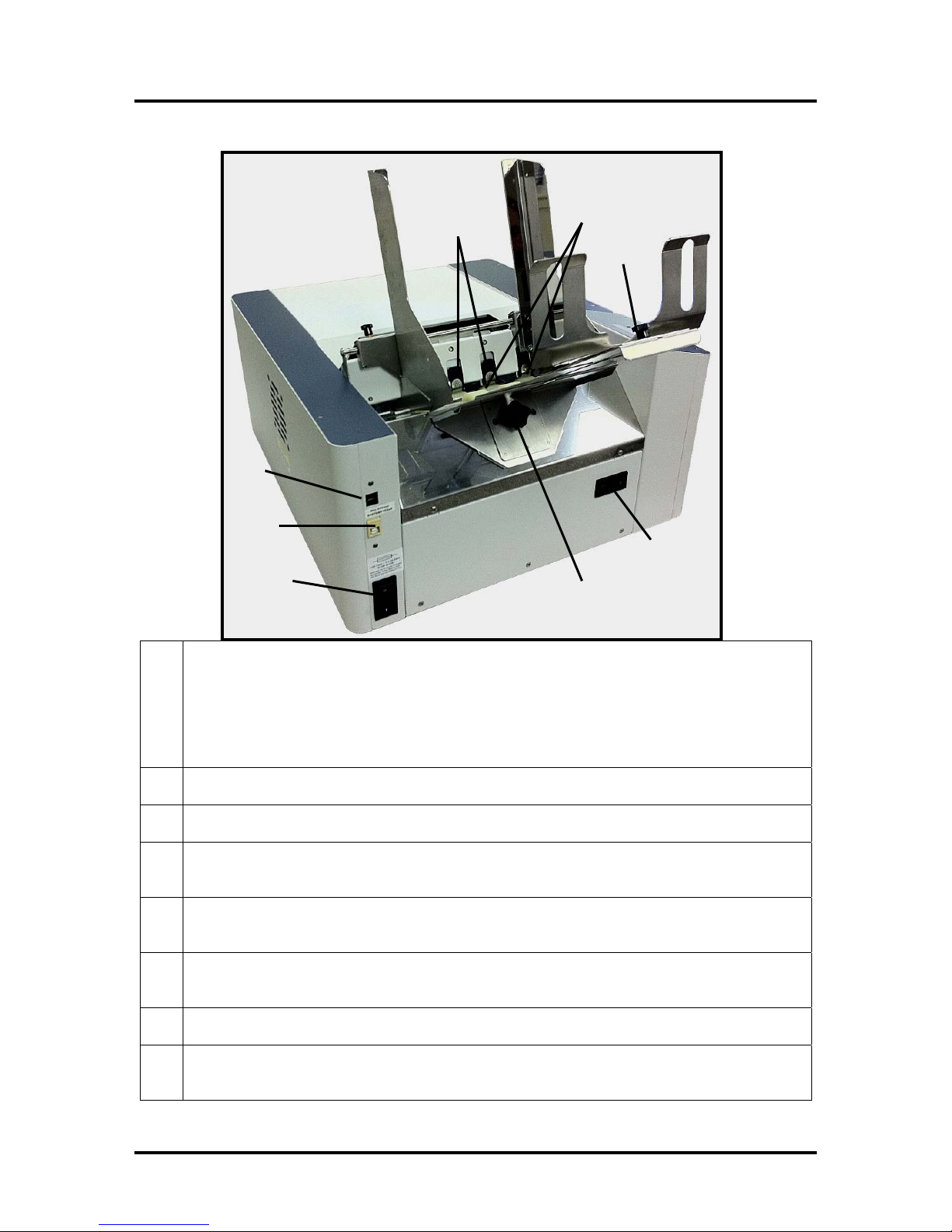
Rear View
1.
Main Power Switch, Receptacle and Fuse – Plug in AC power cord here. Switch turns main
power on or off. Fuse provides over-current protection. Fuse rating: 2.5A, 250V, slow blow.
CAUTION: Make sure power cord is disconnected from printer before checking/replacing fuse.
WARNING: Press the ON/OFF Button, located on control panel, to properly shut-down the print
engine. Wait until all control panel lights turn off, before you turn off the main power switch.
2. USB Port Connection – (USB 2.0) The USB cable attaches to the printer here.
3. Network Connection – (Ethernet) The network cable plugs in here.
4. Sheet Separators – Used to separate a single piece of media from the stack. There are four sheet
separators on this printer.
5. Feed Rollers – Delivers the bottom piece of media, from the stack, through the separation area
and under the forwarding rollers. There are eight feed rollers on this printer.
6. Media Support Wedge Thumb Screw – Used to secure the Media Support Wedge to the Rear
Media Support Guide.
7. Counter – LCD displays number of pieces run for a given job. Reset button zeros counter.
8. Rear Media Support Guide Knob – Attaches the Rear Media Support Guide to the body of the
printer.
SECTION 1
GETTING ACQUAINTED
4
1
5
2
3
46
7
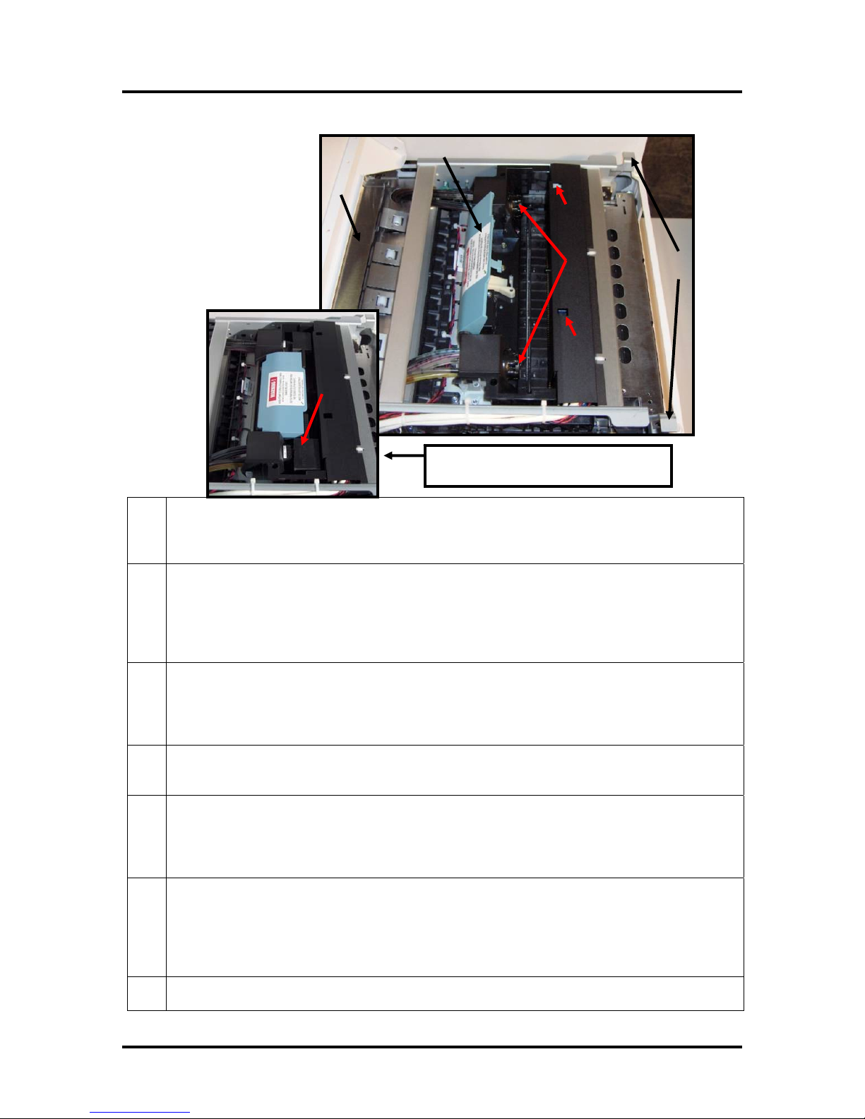
Print Engine with printhead cartridge
installed and printhead latch closed.
Print Engine Area
1.
Antistatic Brush Assembly – This assembly contains an antistatic brush that is used to help
reduce static energy and remove paper dust from the media. This assembly also contains upper
pressure rollers and fingers that help guide the paper into the print engine.
2.
Printhead Latch – When lowered and locked this device connects the Ink Couplings with the
Printhead Cartridge. Note: The printhead latch on your printer may be blue or black.
WARNING! Never attempt to open the printhead latch manually, when in the closed/locked
position. Sever damage will result. Use the Printhead Release function from the Toolbox utility on
your PC or press the Printhead Latch Release button if a computer is not available.
3.
Clean Printhead Button – The button located below this opening can be used to enable a “Level 1
Cleaning” cycle. Insert a non-conductive tool (i.e. plastic pen) into the opening provided, and
lightly press the button.
Additional levels of cleaning can be enabled from the M Series Driver services.
4. Ink Couplings – These devices connect the ink tubes to the printhead cartridge. The printhead
latch is used to engage or disengage these devices from the printhead cartridge.
5.
Printhead Latch Release Button – The button, located below this opening, can be used to initiate
the printhead latch release cycle. Insert a non-conductive tool (i.e. plastic pen) and lightly press the
button. If the system is primed it will run a deprime cycle before releasing the latch. This feature
can also be initiated from the Toolbox utility and M Series Driver services.
6.
Print Engine Latches – Lift up on both latches, at the same time, to release and swing open the
top section of the Print Engine.
CAUTION! Do NOT open the Print Engine while the printer is operating.
Make sure the Print Engine is closed and locked before operating.
Do NOT open the Print Engine to an angle greater than 60º.
7. Printhead Cartridge – Memjet® printhead; produces an 8.5” wide, full color, print area.
SECTION 1
GETTING ACQUAINTED
5
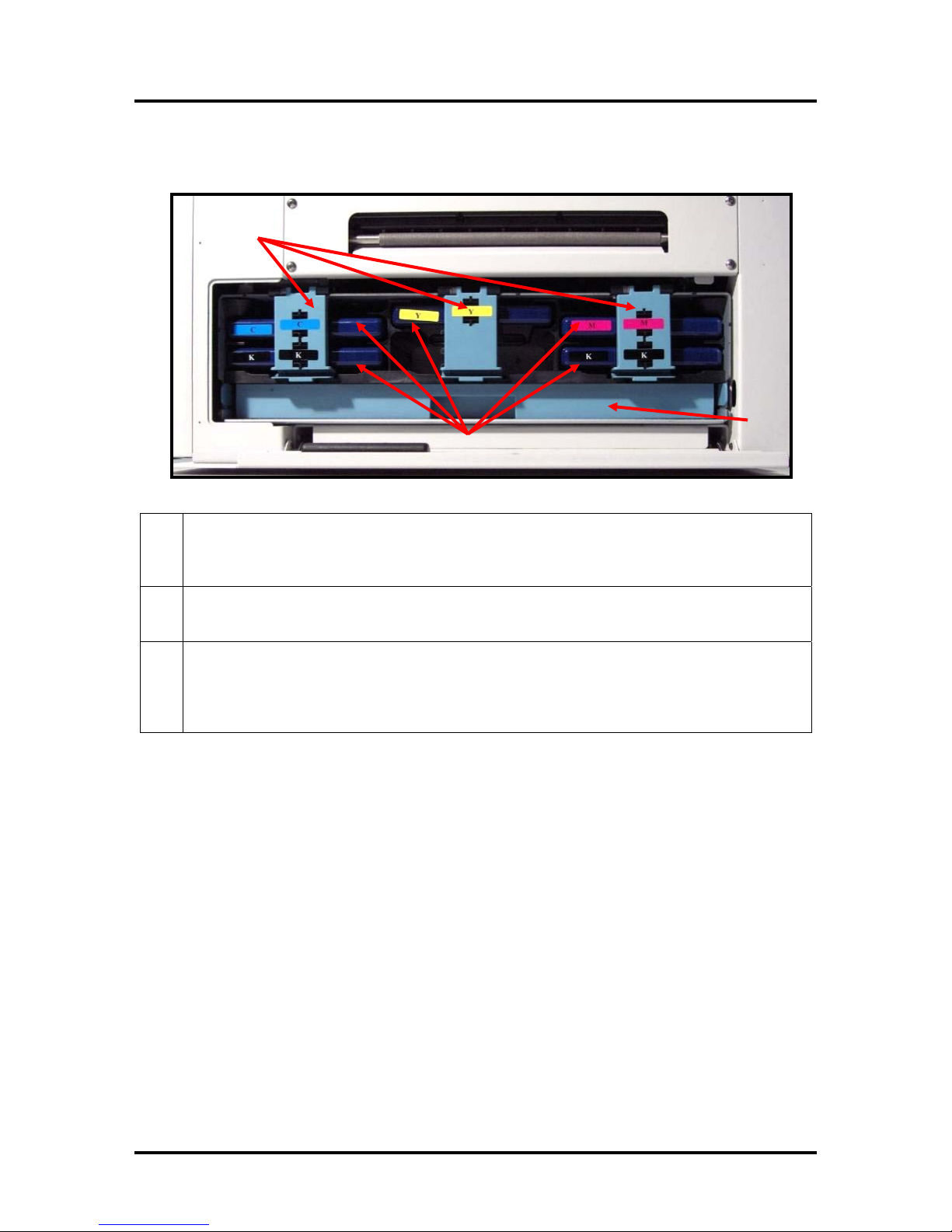
Behind the Ink Tank Door
2
1
3
1.
Ink Tank Securing Latches – Used to hold the Ink Tanks in the slots.
NOTE: Please be sure that both sides, at the bottom part of the latch, are engaged.
2. Ink Tanks – Five Ink Tanks are used in the printer.
Cyan (C), Yellow (Y), Magenta (M), Black (K), Black (K)
3.
Ink Waste Tray –The purpose of this tray is to catch any waste ink produced by the system. This
tray is filled with absorbent material.
The tabs located at the left and right sides of the tray; secure the tray to the print engine frame.
Please be sure the tabs “click” into the frame to secure the tray’s position.

SECTION 2
INSTALLING THE PRINTER
6
Section 2 – Installing the Printer
Before using the Formax ColorMax 7 printer the following must be done:
• Upon delivery; inspect packaging and report any issues to Carrier.
• Choose a location for the printer
• Unpack and assemble the printer
• Install the Printer Software (Drivers and Toolbox)
• Install the Ink Tanks
• Install the Printhead
• Set up the feed on the printer to accommodate your media (covered in Operating the Printer).
Transport Inspection
The printer is shipped in appropriate packaging so that, under normal shipping conditions, it reaches its
destination without damage.
NOTICE: Report damage to the carrier. The carrier is liable for any damage during transport.
Transport and storage should take place under the following conditions:
- At temperatures between -25°C and +50°C (-13 °F to 122 °F).
- At a relative air humidity between 5% and 95%, non-condensing.
- At an atmospheric pressure between 70 kPa and 105 kPa.
Exposure to conditions that are not permissible may lead to damage which is not externally visible.
IMPORTANT Please save the packaging materials for future use! It will be required if you ever need to
ship the printer. Before shipping; please refer to the appendix section “Preparing the Printer for Transport”.
Tools Needed
• Knife and scissors to open packaging
• #2 Philips head Screwdriver
• Carpenters Level (recommend using 18” or longer level)
• Protective gloves should be worn to avoid getting ink on hands when removing protective
packaging materials from the ink coupling areas, the Ink Tank areas, and when
installing/removing Printhead Cartridge and Ink Tanks.
Choosing the Location
The Formax ColorMax 7 should be placed on a sturdy, level, worktable or cabinet at least 9 inches from
any walls. Protect the ColorMax 7 from excessive heat, dust, and moisture – avoid placing it in direct
sunlight.
Work-Table Surface Must be Level
The surface that the printer is placed upon must be level, front to back and side to side. Use a
carpenter’s level to verify that the surface is level. If the surface is not level the printer will not perform
properly. Do NOT move the printer while the power is on.
Operation should take place under the following conditions:
- At temperatures between +15°C and +35°C (-59 °F to 95 °F).
- At a relative air humidity between 20% and 80%, non-condensing.
- At an atmospheric pressure between 70 kPa and 105 kPa.
Exposure to conditions that are not permissible may lead to damage which is not externally visible.
Allow the printer, printhead and ink tanks to acclimate to ambient temperature before using the printer.
Other manuals for ColorMax 7
2
Table of contents
Other Formax Printer manuals


