FORSTRONG FH-6300 User manual

PAGE 1
2 1
rooDfoediSlluProoDfoediSlluP
rooDfoediShsuProoDfoediShsuP
THIS IS A LEFT HAND DOOR THIS IS A RIGHT HAND DOOR
CLOSING SPEED
LATCHING
SPEED
CLOSING
VALVE
LATCH
VALVE
Regular Arm Installation
Closer installs on PULL/HINGE
side of door
DOOR CLOSER ADJUSTMENTS
NOTE :Closing arcs("CLOSE"and"LATCH") are controlled by two(2)separate speed adjusting valves.
Adjust the CLOSING speed a rst and then adjust the LATCHING speed.
1. "CLOSING"speed adjustment is accomplished by full rotations of the speed adjusting valve.
-Turn the speed adjusting valve CLOCKWISE for a SLOWER closing speed.
-Turn the speed adjusting valve COUNTER-CLOCKWISE for a FASTER closing speed.
2 "LATCH" speed adjustment is accomplished by full rotations of the speed adjusting valve.
-Turn the speed adjusting screw CLOCKWISE for a SLOWER closing speed.
-Turn the speed adjusting screw COUNTER-CLOCKWISE for a FASTER closing speed.
Top Jamb Installation
Closer Installs on Frame on
PUSH/STOP side of door.
Parallel Arm Installation
Closer installs on PUSH/STOP
side of door. * Optional
illustrated
Non Hold Open Arm
Left Hand Door-LH
Right Hand Reverse -RHR
See Page 2
illustrated
Non Hold Open Arm
Right Hand Door-RH
Left Hand Reverse -LHR
See Page 3
illustrated
Non Hold Open Arm
Right Hand Door-RH
Left Hand Reverse -LHR
See Page 4
Hinge Edge
of Door
Hinge Edge
of Door
CHART TO
DETERMINE HAND
OF DOOR
NOTE: These instructions apply only to closers equipped with backcheck action.
To increase backcheck intensity, turn "BC" valve clockwise.
To decrease backcheck intensity , turn"BC" Valve counter-clockwise.
OPENING CYCLE
INCREASE
DECREASE
Never close This
valve completely
BACKCHECK ADJUSTMENT
Backcheck
Range
CLOSING CYCLE
BC
A6-1/2
(165.1mm) 1-3/4(44.4mm)
1-1/4 (32 mm)
8-3/16(208mm)
3/4(19mm)
1(25.4mm)
Hinge
or
Pivot
OPENING
To120°
120°-180°
6-1/2(165.1mm)
DIM.A DIM.A
6 (152 mm)
4(101.6mm) 3-1/2 (89mm)
A6
(152mm) 1-3/4(44.4mm)
1-1/4 (32 mm)
9-1/16(230mm)
3/4(19mm)
1(25.4mm)
Hinge
or
Pivot
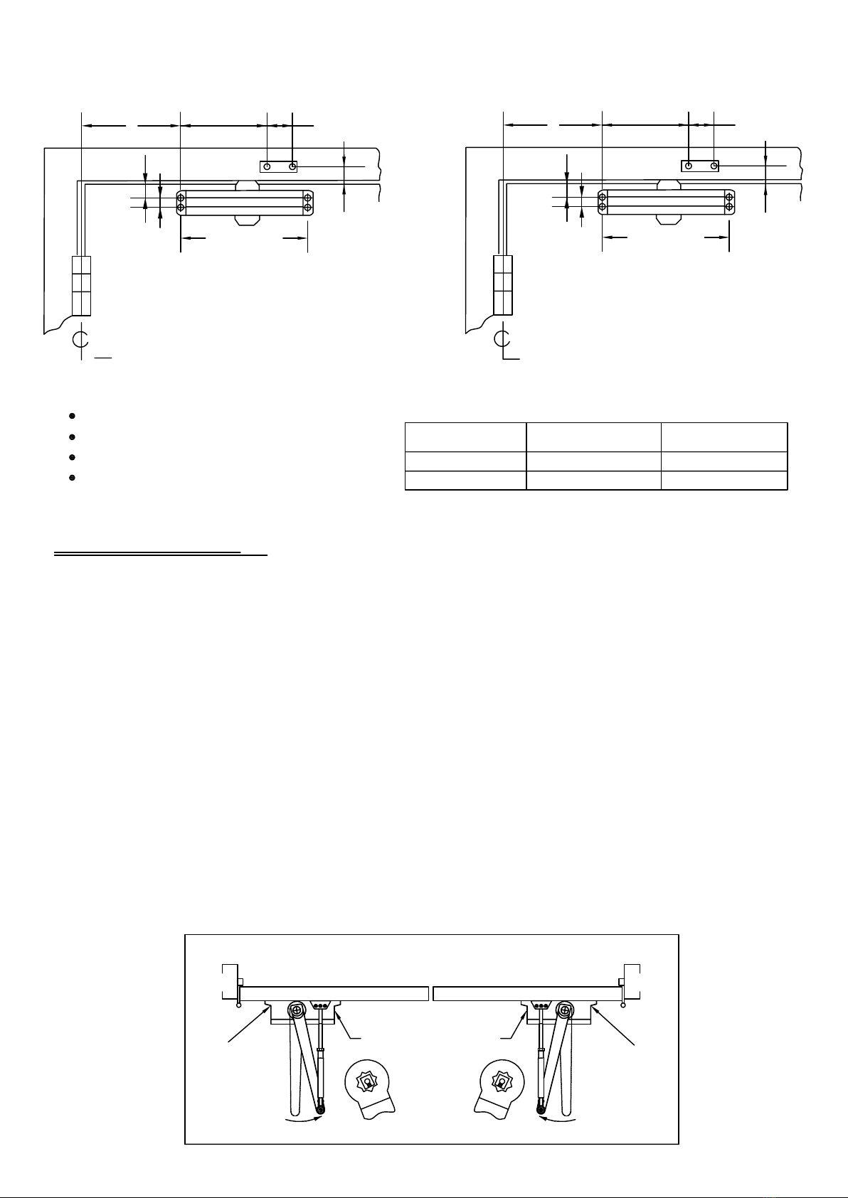
REGULAR ARM (PULL SIDE) Mounting
Size 4,5
Size 2 ,3
Size 2&3 Size 4&5
1. Select door opening angle and use dimensions shown above.
Mark four (4) holes on door leaf for closer body and two (2) holes on frame for arm shoe.
2. Drill pilot holes in door leaf and frame for #14 all-purpose screws for wood door/frame.
Or drill and tap for 1/4-20 machine screws for metal door/frame
3. Install forearm/arm shoe assembly to frame using provided screws.
4. Mount closer on door using provided screws. SPEED ADJUSTING VALVE MUST BE POSITIONED TOWARD
HINGE EDGE
5. Install main arm to top pinion shaft, perpendicular to door. Secure tightly with provided arm screw/washer assembly.
6. Adjust length of forearm so that forearm is perpendicular to frame when assembled to preloaded main arm (see below
iIlustration). Secure forearm to main arm with provided screw/washer assembly
7. Snap pinion cap over shaft at bottom of closer. If the slim cover is packed, please fix it by provided screws.
8. Adjust the door closer, following instructions as shown on page 1.
INSTALLATION SEQUENCE
Top View Typical Installation
SPEED
ADJUSTING
SCREW
SPEED
ADJUSTING
SCREW
"BC"
ADJUSTING SCREW
Preload Preload
Right hand door Left hand door
s
L
R
s
L
R
PAGE 2
Right hand door shown
Left hand door opposite
Dimensions are in inches(mm)
Do not scale drawing
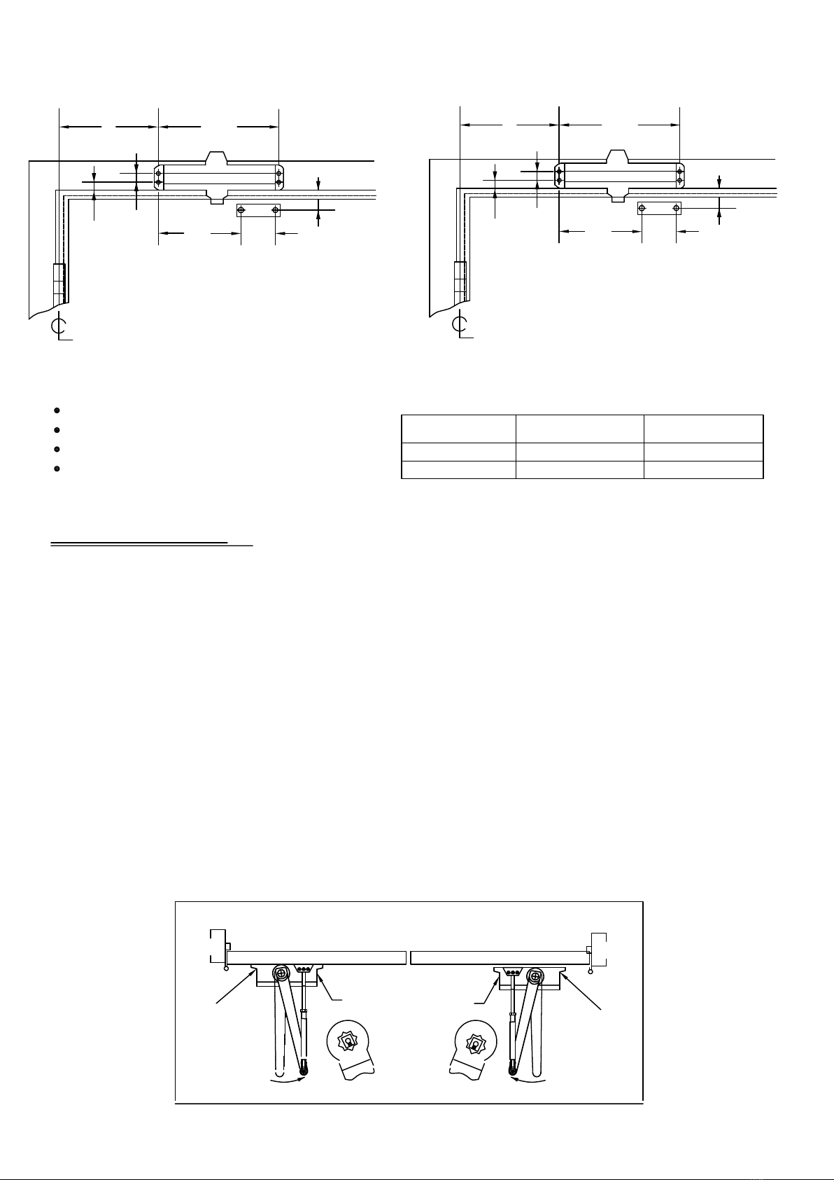
TOP JAMB (PUSH SIDE) Mounting
A8-3/16(208mm)
3/4(19mm)
1/2(12.7mm) 6-1/14
(158.7mm)
1-3/4(44.4mm)
1-3/4(44.4mm)
Hinge
or
Pivot
A9-1/16(230mm)
3/4(19mm)
1/2(12.7mm) 6
(152 mm) 1-3/4(44.4mm)
1-3/4(44.4mm)
Hinge
or
Pivot
OPENING
To120°
120°-180°
6-1/2(165.1mm)
DIM.A DIM.A
4(101.6mm)
6(152 mm)
3-1/2 (89mm)
Size 2&3 Size 4&5
1. Select door opening angle and use dimensions shown above.
Mark four (4) holes on door leaf for closer body and two (2) holes on frame for arm shoe.
2. Drill pilot holes in door leaf and frame for #14 all-purpose screws for wood door/frame.
Or drill and tap for 1/4-20 machine screws for metal door/frame
3. Install forearm/arm shoe assembly to frame using provided screws.
4. Mount closer on door using provided screws. SPEED ADJUSTING VALVE MUST BE POSITIONED TOWARD
HINGE EDGE
5. Install main arm to top pinion shaft, perpendicular to door. Secure tightly with provided arm screw/washer assembly.
6. Adjust length of forearm so that forearm is perpendicular to frame when assembled to preloaded main arm (see below
iIlustration). Secure forearm to main arm with provided screw/washer assembly
7. Snap pinion cap over shaft at bottom of closer. If the slim cover is packed, please fix it by provided screws.
8. Adjust the door closer, following instructions as shown on page 1.
INSTALLATION SEQUENCE
Top View Typical Installation
SPEED
ADJUSTING
SCREW
SPEED
ADJUSTING
SCREW
"BC"
ADJUSTING SCREW
Preload Preload
Right hand door Left hand door
s
L
R
s
L
R
Left hand door shown
Right hand door opposite
Dimensions are in inches(mm)
Do not scale drawing
PAGE 3
Size 4,5
Size 2 ,3

3/4(19mm)
A
B
9-1/16(230mm)
OPENING
To120°
120°-180°
DIM.A
10-3/4(273mm)
8-3/4(222.2mm)
DIM.B
7-13/16(198.4mm)
5-5/8(142.9mm)
DIM.A
7-3/4(197mm)
5-3/4(146mm)
DIM.B
6-1/8(156mm)
4-1/8(105mm)
PARALLEL ARM (PUSH SIDE) Mounting
3 (76mm)
Size 2&3
5/16(8mm)
7/16(11mm)
3/8(9.5mm) 3/8(9.5mm)
2(50.8mm)
2-3/4(69.8mm)
3/4(19mm)
A
B
8-3/16(208mm)
3-3/8(85.7mm)
5/16(8mm)
7/16(11mm)
3/8(9.5mm) 3/8(9.5mm)
2(50.8mm)
2-3/4(69.8mm)
Size 4&5 Size 4&5
Size 4,5
Size 2,3
Size 2&3
1. Select door opening angle and use dimensions shown above .
Mark four (4) holes on door for door closer and four(4) holes underside of frame for paralle l bracket.
2. Drill pilot holes in door leaf and frame for #14 all-purpose screws for wood door/frame.
Or drill and tap for 1/4-20 machine screws for metal door/frame.
3. Mount closer on door using provided screws.
SPEED ADJUSTING VALVE MUST BE POSITIONED AWAY FROM HINGE EDGE
4. Install parallel Arm Bracket to frame using provided screws.
5. Using a wrench on the square shaft at bottom of closer, rotate shaft approximately 45 degrees toward hinge edge of door.
Hold and place main arm on top shaft of closer at proper index mark as illustrated .
FOR LEFT HAND DOOR "L"(illustration " A"). FOR RIGHT HAND DOOR "R"(illustration "B").
Tighten arm screw with Lock-washer securely.
6. Remove arm shoe f rom forearm and discard. Install rod end of forearm to bracket using provided screw/washer assembly.
7. Adjust length of adjustable forearm so that main arm is parallel to frame.
8. Adjust the door closer, following instuctions as shown on page 1.
INSTALLATION SEQUENCE
(A) (B)
Parallel arm Installation
Speed screws
Right hand door
Left hand door
S
R
L
S
L
R
45° 45°
Left hand door shown
Right hand door opposite
Dimensions are in inches (mm)
Do not scale drawing
Hinge
or
Pivot
PAGE 4
Popular Door Opening System manuals by other brands

Dormakaba
Dormakaba RTS88 installation instructions

Becker
Becker A100/25 5E Assembly and operating instructions

Automatic Technology
Automatic Technology TEMPO ATS-2 installation instructions

Dormakaba
Dormakaba RTS Series installation instructions

Dorma
Dorma AGILE 150 Installation instruction

Visionis
Visionis VIS-440 Series installation manual

Cal-Royal
Cal-Royal N-77CVR installation instructions

Besam
Besam SW200i owner's manual

TOPP
TOPP M200 Instructions for installation and use

Raynor
Raynor ControlHoist CMT Installation instructions manual

Dictator
Dictator DICTAMAT 50 BK-Z Technical manual

Assa Abloy
Assa Abloy Adams Rite EX88 Preparation Guide and Installation Instructions


