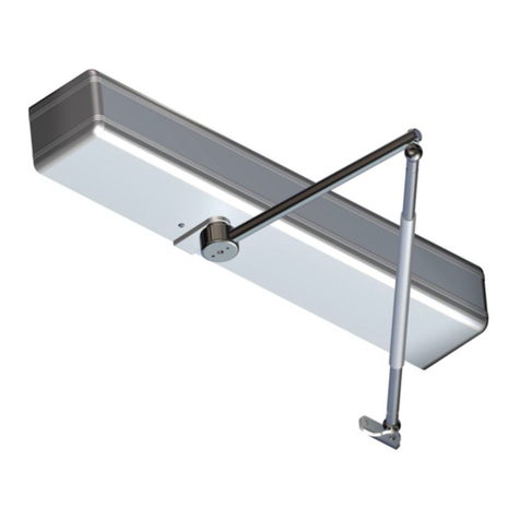
Label Neptis SMP User manual

English
Translation of the ORIGINAL INSTRUCTIONS
Operator for
automatic
swing doors
NEPTIS-SMP-16005_GB_Rel.2.2_09/2016 - CD0420GB
GB
SMP
NEPTIS

INDEX:
GENERAL SAFETY WARNINGS page4
GENERAL SAFETY OBLIGATIONS 4
1)MODEL DESCRIPTION 5
2)TECHNICAL SPECIFICATIONS 5
MECHANICAL SECTION
3)COMPONENTS OF THE NEPTIS SMP OPERATOR 6
4)PRELIMINARY CHECKS 7
5)TECHNICAL DRAWINGS 8
5.1) ASSEMBLY OF THE OPERATOR ON THE LINTEL FROM THE HINGE SIDE BDT2 SLIDE PULL ARM 8
5.2) ASSEMBLY OF THE OPERATOR ON THE LINTEL FROM THE HINGE SIDE BSG 150/250 ELBOW ARM 9
5.3) ASSEMBLY OF THE OPERATOR ON THE LINTEL FROM THE SIDE OPPOSITE OF THE HINGE BSS2 ARTICULATED PUSH ARM 10
5.4) ASSEMBLY OF THE OPERATOR ON THE LEAF FROM THE HINGE SIDE BSS2 ARTICULATED PUSH ARM 11
6)MOVEMENT TRANSMISSION ARMS 12
6.1) BDT2 SLIDE PULL ARM 12
6.2) BSG 150 / BSG 250 ELBOW SLIDING ARM 12
6.3) SLIDING GUIDE FOR PULL ARM 13
6.4) BSS2 ARTICULATED PUSH ARM 13
6.5) EXTB-Z TAPERED PIN 14
6.6) EXTENSION FOR EXTC-Z TAPERED PIN 14
7)PREPARING AND ASSEMBLING THE OPERATOR 15
7.1) REQUIRED TOOLS 15
7.2) OPERATOR CONTROL 15
7.3) OPERATOR ASSEMBLY 16
7.4) INSERTING THE ARM'S TAPERED PIN 16
7.5 REMOVING THE TAPERED PIN 16
8) SELECTING THE OPENING DIRECTION IN FUNCTION OF ARM 17

ELECTRONIC SECTION
9)ELECTRIC ARRANGEMENTS 18
10)ELECTRIC CONNECTIONS 19
11)PWN-T POWER SUPPLY MODULE AND ELECTRIC WIRING 20
12)L-NEP LOGIC BOARD 22
13)N-DSEL DIGITAL PROGRAMMER – SCOPE AND CONNECTIONS 22
14)COMMISSIONING OF AUTOMATED DEVICE (INITIAL SET-UP) 23
14.1) FIRST START OF N-DSEL DIGITAL PROGRAMMER 23
14.2) USE OF N-DSEL DIGITAL PROGRAMMER 23
14.3) SERIAL COMMUNICATION SET-UP 23
14.4) INITIAL SET-UP 24
14.5) FUNCTIONAL TESTING 26
14.6) INPUTS DIAGNOSTICS 26
15)PROGRAM SELECTORS 27
15.1) MANUAL PROGRAM SELECTOR 27
15.2) EV-MSEL MECHANICAL KEY SELECTOR 27
15.3) N-DSEL DIGITAL PROGRAMMER USED LIKE PROGRAM SELECTOR 28
16)GENERAL PROGRAMMING MENU 30
17)FUNCTIONS AND REGULATIONS 31
17.1) FUNCTIONS SETTING 31
17.2) PARAMETERS SETTING 35
18)LANGUAGE 39
19)PASSWORD MANAGEMENT 39
19.1) HOW TO CHANGE THE TECHNICAL PASSWORD 40
19.2) HOW TO CHANGE THE PRIMARY PASSWORD 40
19.3) HOW TO CHANGE THE SERVICE PASSWORD 41
19.4) ENABLING USER (primary and service) PASSWORD USAGE 42
19.5) DEACTIVAING THE USER PASSWORD USAGE 42
20)INFORMATION AND EVENTS MEMORY 43
21)MAINTENANCE 45
22)ELECTRIC LOCK APPLICATION 45
22.1) ELECTRIC LOCK / ELECTRIC STRIKE 45
22.2) MAGNETIC LOCK 46
23)SAFETY SENSOR DEVICES 46
23.1) SENSOR OA-EDGE T 46
23.2) SENSOR 4SAFE ON SW 48
23.3) SENSOR TOPSCAN-S 48
24)EN/RF1 RADIO RECEIVER 49
25)DISABLED PEOPLE COURTESY FUNCTION 50
26)DOUBLE LEAF DOOR SET 51
26.1) ELECTRICAL WIRING FOR A DOUBLE LEAF DOOR SET 51
26.2) DOOR SET-UP 51
26.3) FUNCTIONAL TESTING 54
26.4) PEDESTRIAN OPENING 54
26.5) CONSIDERATION ON THE USE OF N-DSEL PROGRAMMER IN A DOUBLE DOOR SYSTEM 55
27)INTERLOCK SYSTEM 56
27.1) INTERLOCK ELECTRIC CONNECTION 56
27.2) INTERLOCK APPLICATION WITH INDEPENDENT INTERNAL RADAR 56
27.3) INTERLOCK APPLICATION WITH ONLY ONE INTERNAL RADAR 57
28)MEANING OF THE ACOUSTIC SIGNAL 58
29)MAINTENANCE PROGRAM 58
DECLARATION OF INCORPORATION OF PARTLY ASSEMBLED MACHINERY 59

4
GENERAL SAFETY OBLIGATIONS
The mechanical and electric installation must be performed by specialised personnel in accordance with current directives
and regulations.
The installer must make sure that the structure to be automated is stable and robust and if necessary, make it this way by making
structural modifications.
Keep product and packaging materials out of children's reach, as they might be a source of danger.
Do not let the children stay or play within the range of the door.
This product was designed and built exclusively for the purpose described in this documentation. Any other use that is not specifically
indicated could adversely impact the condition of the product and the safety of people.
Label accepts no responsibility for incorrect product installation and usage, as well as for any damages caused by changes made
without its prior consent.
Label is not responsible for the construction of the fixtures to be motorised.
The IP31 degree of protection requires that the operator is installed only on the inner side of buildings.
This product cannot be installed in explosive environments or atmospheres, or in the presence of flammable gases or fumes.
Make sure that the characteristics of the electric distribution network are compatible with the technical data indicated in this manual
and that upstream of the system there is an omnipolar switch with an opening distance of the contacts of at least 3mm and a residual
current device.
Connect the ground conduit of the electric system.
The automatic door must be checked, started up and tested by skilled and well-prepared personnel.
A technical dossier must be prepared for every automation as required by the Machine Directive.
Disconnect the power supply before working on the automation and before opening the cover.
Maintenance is of fundamental importance for the proper operation and safety of the automation. Check the efficiency of all parts every
six months.
Use only original spare parts for maintenance and when replacing product components.
Cleaning operations must be performed with the power supply disconnected, using a damp cloth. Do not deposit or let water or other
liquids penetrate into the Neptis SMP operator or the accessories that are part of the system.
GENERAL SAFETY WARNINGS
Carefully read this instruction manual for the safe installation and operation of the automatic door.
Improper installation and incorrect use of the product could cause serious injury.
Keep the instruction manual for future reference.
The installer must provide all the information about operation and provide the system user with the user manual delivered with the
product.
MEANING OF THE SYMBOLS USED IN THESE INSTRUCTIONS
DANGER: Indication of dangerous situations that could cause material damage and personal injury.
WARNING: Identifies the procedures that must be understood and followed to prevent product damage or malfunctions.
NOTE: To point out and place attention on important information.
It is recommended to take out a maintenance contract.
Risk assessment
The automatic swinging doors must be designed and installed in a way to protect users against the risk and danger of crushing, impact
and shearing between the door and adjacent parts near the door.
The person responsible for starting-up the automation must perform a risk assessment based on the place of installation and the type
of users that could use the automatic door.
The dangers of crushing and shearing related to the secondary closing edge must be prevented
either structurally or by supplementary protective measures (rubber covers, for example).
Any residual risks must be properly signalled.
A = Main closing edge
B = Secondary closing edge
C = Opposite closing edge
The Neptis SMP operator, as required by EN16005 standard, must be equipped by protection devices (sensors) in accordance with
EN12978

1) MODEL DESCRIPTION
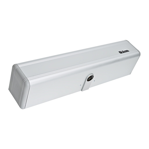
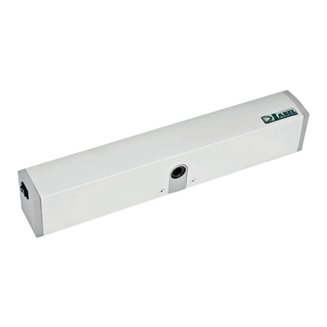
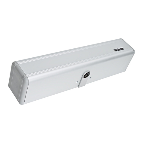
The Neptis SMP operator has an electro-mechanical motor for opening the pedestrian swing doors.
The electronic control equipment is located inside the operator.
A list of the operator models for Neptis SMP swinging doors produced by Label is provided below:
The Neptis SMP operator can be used with a slide pull arm or with an articulated push arm.
The operator must be installed in indoor environments.
All models are reversible, therefore in the case of a power failure the door can be opened manually.
Before starting with assembly check the technical drawings in paragraph 5. A drawing of the application is provided for every type of
arm, with the installation dimensions and a chart that provides the weight limits based on the length of the door leaf.
The technical data provided in the charts refers to a typical installation, but the data can be influenced by variables present in every
system, such as friction, environmental conditions, alignment of the leaf hinge, etc....
2) TECHNICAL SPECIFICATIONS
POWER SUPPLY
POWER
POWER SUPPLY OF EXTERNAL ACCESSORIES
ELECTRIC MOTOR
115/230Vac +/-10%, 50-60Hz
120W
24Vdc, 1A
24Vdc
5
ARTICOULATED ARM SLIDING ARM
WEIGHT
PROTECTION DEGREE
AMBIENT TEMPERATURE
FREQUENCY OF USE
LIMIT SWITCH AND ANTICRUSHING SAFETY
REACTION TO OBSTACLES
OPENING TIME for 95°
CLOSING TIME for 95°
PAUSE TIME
10,8 Kg.
IP31
-15°C +50°C
continuous
encoder controlled
reversal of direction
4 - 12 seconds adjustable
5 - 15 seconds adjustable
0 - 20 seconds adjustable
OPERATOR WITH BATTERY DIMENSIONS (LxHxD) 730 x 110 x 120 mm
NEPTIS SMP
Min Max Min Max
18 18
72 144
18 18
114 144
15 15
60 120
15 15
95 120
MANUAL CLOSING TORQUE (Nm)
AUTOMATIC CLOSING TORQUE (Nm)
MANUAL TORQUE TO OPEN (Nm)
AUTOMATIC OPENING TORQUE (Nm)
REFERENCE VALUES FORCE

MECHANICAL SECTION
3) COMPONENTS OF THE NEPTIS SMP OPERATOR
6
1
2
3
4
5
6
7
LEGEND:
L-NEP LOGIC CARD
PWN-T ELECTRICAL WIRING AND POWER SUPPLY CARD
GEARMOTOR WITH ENCODER
SPRING PRELOAD REFERENCE LINE
INNER WIRING BETWEEN THE L-NEP and PWN-T CARDS
PLASTIC PLATE
TRANSFORMER

4) PRELIMINARY CHECKS
Before assembling the automation, make sure the following requirements have been met:
• The operator support structure must be solid and must not show any significant deformations.
• The leaf structure must be rigid and robust.
• The leaf pivots must be suitable and in a good condition.
• The lenght and weight of the leaf must lie within the operating limits of the operator (maximum recommended height 3 mt).
• The leaf must move in a regular manner without friction along its entire stroke.
• The door requires mechanical end stops consisting of a mechanical retainer in the opening position and a final stopper when
closed.
The mechanical stop in the open position is not supplied with the operator.
If the wall to which the operator will be fastened is not suitably resistant and reliable, a predrilled metal plate is available, upon request,
to which the Neptis SMP can be fixed.
7
1
3
3
3
2
2
2
4
4
4
Base Operator NEPTIS SMP
Elenco Parti / Part List
Descrizione/Description
Qtà/Qty
Parte/Item
Piastra / Plate1
1
Vite / Screw M6 x 163
2
Rondella / Washer3
3
Vite / Screw M6 x 20
3
4

5) TECHNICAL DRAWINGS
8

9

10
At door open a mechanical end-stop has
to be installed.

11
At door open a mechanical end-stop has
to be installed.

6.1) BDT2 SLIDE PULL ARM
a) Insert the M8 x 70 screw (2) in the tapered pin (1)
b) Insert the sliding arm (3) in the closed shell (4)
c) Insert the tapered pin (1) above the sliding arm (3), through the closed shell (4)
d) Strongly tighten the M6 x 30 screws (5) to block the sliding arm (3) on the tapered pin (1)
e) For the assembly of the sliding guide, see paragraph 6.3
f) The pin (6) must be inserted in the sliding guide runner
6.2) BSG 150/ BSG 250 ELBOW SLIDING ARM
a) Insert the M8 x 70 screw (2) in the tapered pin (1)
b) Insert the long rod of the arm (4) in the closed shell (3)
c) Insert the tapered pin (1) above the long rod of the arm (4), through the closed shell (3)
d) Strongly tighten the screws M6 x 30 (5) to block the long rod of the arm (4) on the tapered pin (1)
e) Insert the rods, long (4) and short (6) in the bush (7) and fasten them with the M10 x 6 screws (8)
f) For the assembly of the sliding guide, see paragraph 6.3
g) The pin (9) must be inserted in the sliding guide runner
6) MOVEMENT TRANSMISSION ARMS
12

6.3) SLIDING GUIDE FOR PULL ARM
a) Fix the sliding guide (1) on the leaf through the holes (6-7),
following the dimensions indicated in the technical drawings in
paragraphs 5.1, 5.2.
b) Insert the runner (3) for the pull arm tapered pin inside the sliding
guide.
c) Insert the striker (5) inside the sliding guide and fix it in the end
of stroke opening position using the dowel.
d) Position the cover casing (2) on the sliding guide (1).
e) Insert the two side panels (4) on the ends of the sliding guide.
6.4) BSS2 ARTICULATED PUSH ARM
a) Insert the M8 x 70 screw (2) in the tapered pin (1)
b) Insert the lever arm (3) in the closed shell (4)
c) Insert the tapered pin (1) above the lever arm (3) through the
closed shell (4)
d) Strongly tighten the M6 x 30 screws (5) to block the lever arm (3)
on the tapered pin (1)
e) Fix the arm plate (9) on the leaf or on the lintel using two
screws according to the dimensions indicated in the technical
drawings in paragraphs 5.3 or 5.4
f) Adjust the length of the telescopic arm (7-8) and tighten the
screws (6)
13

6.5) EXTB-Z TAPERED PIN
Use the EXTB-Z tapered pin if a larger distance is required between the operator and the arm in comparison to the standard tapered pin.
For the assembly dimensions follow the technical drawings in par. 5.
For the assembly, follow the steps shown in the following figures:
insert the M8 X 90 screw in the tapered pin (A), insert the arm in the closed shell (B), insert the tapered pin in the arm (C) and tighten
the two M6 X 20 screws (D).
6.6) EXTENSION FOR EXTC-Z TAPERED PIN
Use the EXTC-Z extension if a larger distance is required between the operator and the arm in comparison to what can be obtained
using the standard and EXTB-Z tapered pins.
Couple the EXTC-Z extension to the standard or EXTB-Z tapered pin (depending on the distance to be reached, see the technical
drawings in par. 5).
For the assembly, follow the steps shown in the following figures:
couple the EXTC-Z extension with the tapered pin and insert the central screw (E), tighten the two M6 X 65 side screws (F), insert the
extension in the arm and tighten the two M6 X 20 screws (G).
14
A B C D
E F G

7) PREPARING AND ASSEMBLING THE OPERATOR
7.1) Required tools:
Tape measure, drill, level, thin flat-head screwdriver, medium-sized
flat-head screwdriver, large cross-head screwdriver, Allen wrenches
with handle (sizes 2.5 – 4 - 5 – 6), flat-head wrench 10.
7.2) Operator control
Remove the operator from its packaging and remove the screws
retaining the cover.
Remove the aluminium cover from its seat, pulling it firmly upwards
and without applying pressure on the sides, if possible.
15
The Neptis SMP operator foresees the possibility of connecting the arm on both sides of the mechanical body and therefore makes it
possible to select the opening movement direction.
Identify the correct side for connecting the pin, based on the type of arm used and the type of operator assembly. Carefully review the
technical drawings in paragraph 5 and the scheme showed in paragraph 8.
The schema in paragraph 8 shows the possible configuration and connection to be performed on NEPTIS SMP drive, depending on the kind
of arm which has been used.
For simplicity, the schema can be summarized in the following points:
ŸUsing the articulated push arm (BSS2): install the drive leaving unchanged the factory settings and please check the
assembly instructions on paragraph 5.
ŸUsing the sliding pull arm (BDT2) or the elbow arm (BSG150/250): remove the cover following the instructions described on
paragraph 7.2, and disconnect the motor and encoder cables from the control unit. Connect then cables CL1404 between the
motor and encoder cables you have just disconnected and the control unit. Install the cover once again and follow the
installation drawings on paragraph 5.

7.3) Operator assembly
Based on the arm to be used and the operator fixing position, refer
to the relative assembly table (par. 5.1 to 5.4), which indicates
where the holes must be made for the assembly of the operator and
the drive arm.
For arm assembly refer to paragraph 6.
To fix the devices use the screws and anchors suitable for the type
of support.
After fixing the operator and arm, follow the next steps for connecting
the arm pin to the shaft output of the Neptis SMP operator.
7.4) Inserting the arm's tapered pin
Make sure that the plastic plate is inserted in the operator's
mechanical body where the output shaft is located, before inserting
the arm's tapered pin.
There are wedges in the arm's tapered pin that must be perfectly
matched with those in the operator output shaft. These serve the
purpose of making sure that the arm's tapered pin always moves
together with the operator's motion transmission shaft.
Insert the arm's tapered pin in the operator output shaft making sure
that the wedges in the two parts are correctly matched and then
firmly tighten the screw fixing the arm's tapered pin.
If leaf movement is regular along the entire stroke, both when opening
as well as when closing, continue with the electrical connections as
described in the electronic part section of the paragraph “Electric
connections”.
16
7.5) REMOVING THE TAPERED PIN
Insert the Allen wrench (6mm.) inside the hole of the tapered pin
without removing the arm rod.
Unscrew the arm's fastening screw, applying greater force in the
final phase in order to remove the tapered pin.

17
8) SELECTING THE OPENING DIRECTION IN FUNCTION OF ARM

18
9) ELECTRIC ARRANGEMENTS
NOTE:
The grey part indicates the survey
zone of radar and sensors.
The number of cables and the
relevant section in mm is indicated
for every device.
2
3
4
5
6
7
EXTERNAL RADAR (4x0,5mm)
INTERNAL RADAR (4x0,5mm)
OPENING CONTROL (2x0,5mm)
PROGRAM SELECTOR (4x0,5mm)
SAFETY SENSOR FOR CLOSING (6x0,5mm)
SAFETY SENSOR FOR OPENING(6x0,5mm)
NEPTIS SMP OPERATOR (mains power supply 3x1,5mm)
ELECTRIC LOCK (2x1mm)
FLOOR STOP
8
9
! The power supply line must be protected against short circuit and dispersion to ground.
! On the power supply mains, provide for an omni-polar switch/selector with contact opening distance of at least of 3 mm.
! Use self-extinguishing cables for electric connections.
! Separate the mains power supply line from the very-low voltage line relative to control and safety accessories.
! On the plastic side panels of the Neptis SMP operator there are the holes that must be broken open, through which the electric cables
must be inserted. The installer must made the power supply cable stable inside the operator and, particularly, limit the peeling of cable
primary sheath so that the air and surface distances are not reduced if a connector detaches from the terminal.
! If operator is installed on a door leaf, perform electric connection by a branching box with suitable flexible unions and pipes, available on
the market.
1
7
5
6
4
3
8
1
9
2
ELECTRONIC SECTION

SAFETY SENSOR FOR CLOSING
+24V-
SAFETY SENSOR FOR OPENING
25 TEST
26 GND
M6
27 AUX3
28 24V
29 O.C.
M7 M8
+
16 17 18 19 20 21
1
AUX1
2
SEN./CL.
M2
3
COMMON
4
5
AUX2
OPEN
COMMON
6
7
M3
M4
8
9
RAD.EX
START
COMMON
10
11
RAD.IN
12
13
B14
15
A
- GND
C N.O. N.C. +EL.
M1
PHASE
NEUTRAL
GND
+24V-
OPEN
DIGITAL
PROGRAMMER N-DSEL
ELECTRIC LOCK
24V
+24V-
INTERNAL RADAR
+24V-
EXTERNAL RADAR
START
BUTTON
230Vac
MAINS POWER SUPPLY
DISCONNECTOR
MANUAL
PROGRAM
SELECTOR
PWN-T
10) ELECTRIC CONNECTIONS
TEST
TEST
24V +13V
-
19
SEN./OP.

! In case of 230Vac mains voltage, put the 4-pole connector of the transformer primary in the J3 connector (230V) of PWN-T board (factory
setting).
! In case of 115Vac mains power supply, put the 4-pole connector of the transformer primary in the J2 (115V) connector of PWN-T board.
TERMINAL BOARD M1
230 Vac power supply: phase to terminal F, neutral to terminal N, ground connection with terminal ground symbol.
! Ground the operator by connecting the ground cable from the line to the Faston connector on the plate the PWN-T board is fastened to.
A cable, connected with ground terminal of PWN-T board, is connected with the second faston.
! The electric line is protected by 2A fuse F1.
TERMINAL BOARD M2
Terminals 1-3-4
MANUAL PROGRAM SELECTOR, located on operator side panel (factory wiring):
closed contact on position I to terminal 1 (AUX1);
central contact to terminal 3 (common);
closed contact on position II to terminal 4 (AUX2);
! For more information on the operating modes of manual program selector, refer to "Program selectors" paragraph.
Terminals 2-3
Input of SAFETY SENSOR FOR CLOSING, N.C. contact.
The operation of safety sensor for closing must be enabled by N-DSEL digital programmer (function F18 ON).
The activation during closing provokes the door reopening.
Terminals 5-7
Input of SAFETY SENSOR FOR OPENING, N.C. contact.
The operation of safety sensor for opening must be enabled by N-DSEL digital programmer (function F19 ON).
The activation during opening stops the door leaf movement; when the sensor deactivates, the opening restarts at low speed.
Terminals 6-7
OPEN input.
Input contact logic state can be selected as N.O. (default condition) or N.C. by N-DSEL digital programmer (function 30).
The activation allows opening the door of all operating programs.
11) PWN-T POWER SUPPLY MODULE AND ELECTRIC WIRING
VOLTAGE CHANGE
115V 230V
115/230V
GROUND
20
OPEN
Other manuals for Neptis SMP
1
Table of contents
Other Label Door Opening System manuals

Label
Label Neptis SLT-B User manual

Label
Label NEXT 75 User manual

Label
Label NEXT 75 User manual

Label
Label ETERNA 90 EASY User manual

Label
Label NEXT 120s User manual

Label
Label NEPTIS/LE User manual

Label
Label ETERNA 70 User manual

Label
Label NEPTIS PLUS User manual

Label
Label T-NFC User manual

Label
Label Neptis SMP User manual
Popular Door Opening System manuals by other brands

C.R. Laurence
C.R. Laurence CRL JACKSON 1295 installation instructions

Automatic Technology
Automatic Technology GDO-6 EasyRoller installation manual

Chamberlain
Chamberlain K1A6636 quick start guide

GEZE
GEZE GC 365 R manual

Dormakaba
Dormakaba G-SR EMR Series Fixing instructions

Schartec
Schartec Prime 600 Installation and operating instructions