Visionis VIS-440 Series User manual

Electric Automatic Door Opener
VIS-440 Series
Installation Manual
www.visionistech.com - Call Us: 1-888-504-3318

• Installation of automatic door should be entrusted to the appointed distributer or
professional installation personnel, or it may be dangerous.
• Installation must be performed by professional installation personnel according
to local law.
• This manual must be kept well for maintenance.
This manual applies for the model numbers below:
VIS-440A-SLIM
VIS-440A-SLIM-BL
VIS-440B-SLIM
VIS-440B-SLIM-BL
We are not responsible for any improper installation of athis product
it is suggest for a professional to install this automatic door opener.
• Safety devices should be in place and operational.
• Have door adjusted as recommended in Owner’s Manual if necessary.
• Have door inspected at least annually by a certified technician.
TYPICAL USED TOOLS
If you choose to use no locks or
any other type of locks that is not
a door strike, this latch must be
remove for proper operation.

1. Introduction of product………………………………………….
2. Technical parameters ………………………………....…….…
3. Swing door mechanism ………………………………………..
4. Components ………………………………………………….…
5. Installation step …………………………………………………
5.1 Installation demonstration ……………………………….
5.2 Installation of bottom plate ………………………………
5.3 Installation of pull bar …………………………………....
5.4 Installation of pull bar for glass door ……………………
5.5 Installation of push bar …………………………………..
5.6 Installation of extensions (Pull Arm) .....………………..
5.7 Installation of extensions (Push Arm) ...………………..
5.8 Mechanism installation ...…….................……………..
6. Wiring diagram ....……………………………………………....
7. Data setting ……………………………………………………..
8. LED display feedback ………………………………………….
9. Trouble shooting ………………………………………………..
1
2
3
4
5-17
5-6
7-8
9-11
12
13
14-17
18-19
20
21-25
26-27
28
29
Content

1. Introduction of Product
Application: Suitable for wooden doors, metal doors and
framed doors. Frameless door needs to be installed with the
glass clamp.
Speed/opening time/open degree/ close force adjustable
Door width: ≤ 1200mm
Door weight: ≤ 440lbs
Open degree: Max 110°
Installation: Open to inside (Pull arm) /open to outside
(Push arm)
Voltage: AC100V-240V, Output 24 DC
Opening Accessories: Function remotes (standard), Wireless
push button, access keypad etc.
Working times: About 2 million cycles.
2
4
6
Suggested products:
1 VIS-440-SLIM Automatic Door Opener
2 VIS-EL104 Electric Strike or
VIS-ML600LED Electromagnetic Lock
3 VS-AXESS-ETL y VS-AXESS-DLX
Access Controllers
4 VIS-7013 Exit Button
5 VIS-8016 Remote control
6 VIS-3000, VIS-3003, VIS-3004, VIS-3005
Keypad/Card Reader
7 VIS-8015 Wireless push button
1
1. 55W high speed DC brushless motor, long service life, low noise.
2. In main and slave mode. Sequence will not change because of encounter an obstacle.
3. Double gear box design, high speed ratio, high strength, can work with doors up to 440lbs.
4. Push and go function.
5. The voltage of the controller is AC100V-240V, which is applicable worldwide.
6. The magnetic lock can be connected directly to the controller without the need for additional power supply.
7. The controller has added the anti-interference function of the sensor, and the sensor can be directly
connected inside and outside the operator.
1
7
3
5

2.Technical Parameters
2
Power: AC 100V-240V
Active open time: 3-7s/90°
Hold open time: 0 - 20s
Temperature: -20°C ~ 55°C ( -4°F ~ 131ºF)
Protection class: IP21
Product weight: 12.2lbs
Product size: 475*81*98mm (18.70*3.19*3.87 inches)
Max open angle: 110°
mm = Door width
Lbs = Door weight
Suitable range
Limited range

3.Swing Door Mechanism
3
Design for Barrier-Free accessibility and convenient for disabled and children.
Swing door mechanism
Dimension: mm (inches)
Pull Bar Push Bar
475mm (18.70in.)
39.5mm (1.56in.)
7.5mm (0.30in) 230mm (9.06in) 230mm (9.06in)
500mm (19.69in)
98mm (3.86in.)
316mm (12.44in)
143mm (5.63in.)
20mm
(0.79in.)
120mm (4.72in)
81mm (3.19in.)
81mm (3.19in.)
81mm (3.19in.)
98mm (3.86in.)

4. Components
4
VIS-440-SLIM
Base
Pull bar
Push arm
Slide rail
Cover
Door operator
Extensions
25mm (0.9843 inches)
50mm (1.9685 inches)

5. Installation Step
5
5.1 Installation demonstration
Installation of PULL BAR type, suited for inswing doors (mechanism is inside).

6
5. Installation Step
5.1 Installation demonstration
Installation of PUSH BAR type, suited for outswing doors (mechanism is inside).
7
5. Installation Step
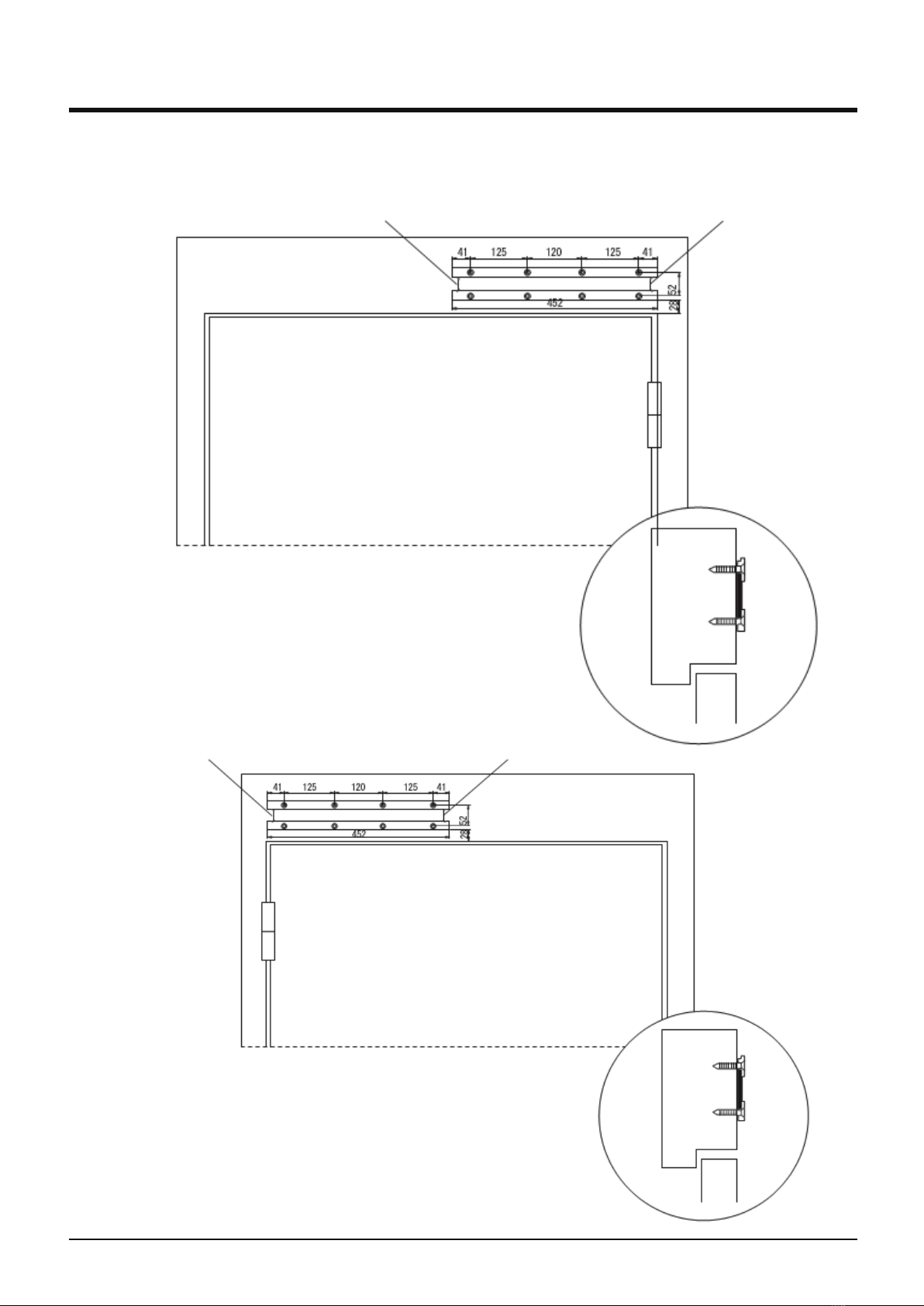
5.2 Installation of bottom plate
Power liner Sensor liner
As the picture shows, fix the bottom
plate on the frame with eight countersunk
head screw.
Operator at right position.
Operator at left position.
As the picture shows, fix the bottom
plate on the frame with eight countersunk
head screw
Sensor liner
Power liner
Installation of pull bar type.

8
5. Installation Step
5.2 Installation of bottom plate
Installation of push bar type.
Power liner
Power liner
Sensor liner
Frame
Bottom
plate
Sensor liner
Frame
Bottom
plate
The distance between the
bottom of the mounting plate
and the door hole is 6mm
The distance between the
bottom of the mounting plate
and the door hole is 6mm
Operator at right position.
Operator at left position.
As the picture shows, fix the bottom
plate on the frame with eight countersunk
head screw.
As the picture shows, fix the bottom
plate on the frame with eight countersunk
head screw.
9
5. Installation Step
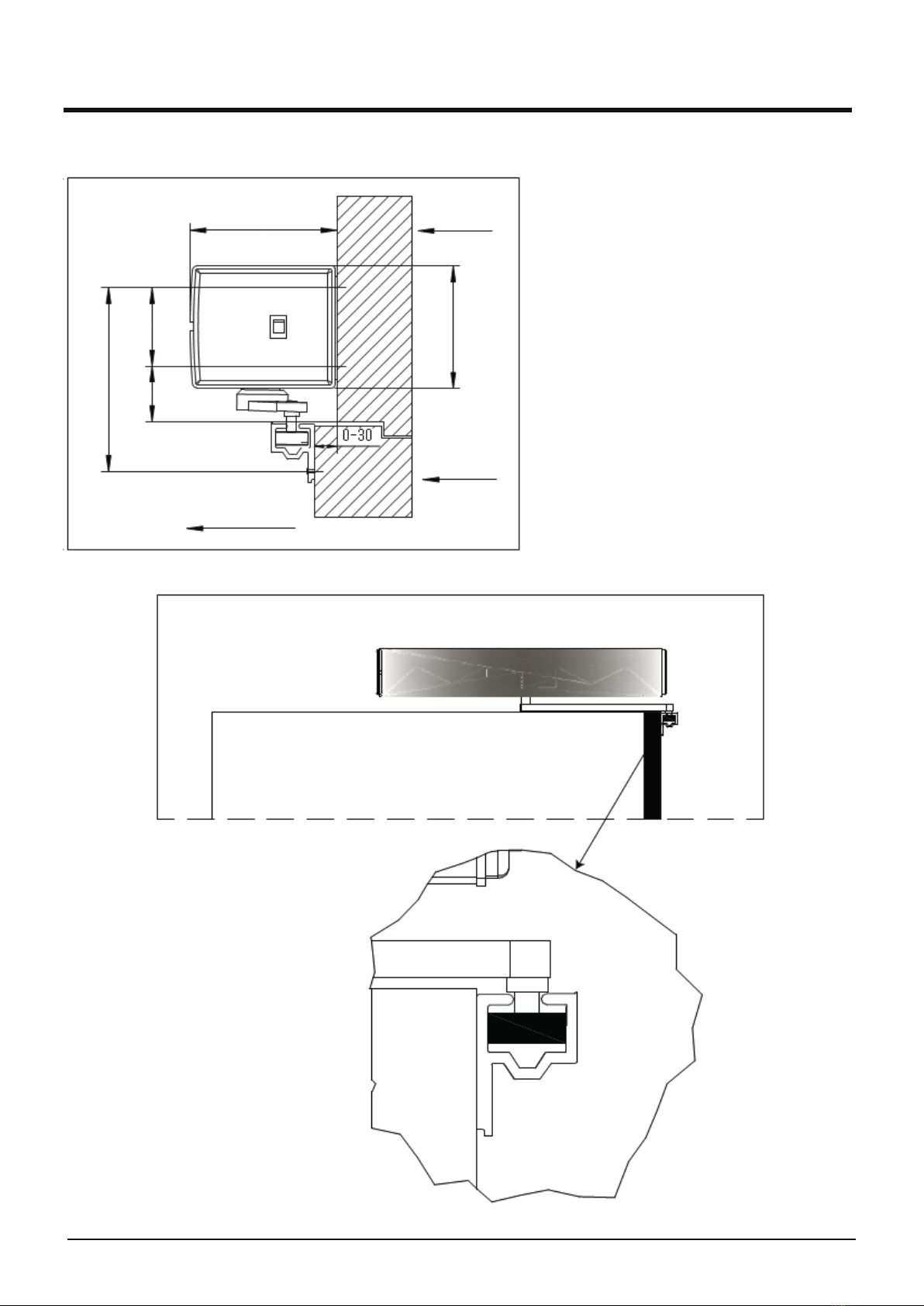
5.3 Installation of pull bar
1. Open the door to 90°, slide the pull
guide roller into track.
2. Fix the Pull bar plate as shown.
3. Move the plate ensure the wheel at
the middle position of track as shown.
4. Hold the plate position, fix the first
screw near center of the shaft.
5. Close the door, repeat step 3,fix
another screw on the other side.
6. Manually move the door to ensure pull
bar work smoothly, adjustment is
required if any resistance is shown
during the operating.
7. Fix the last screw.
Door leaf
Open direction
98mm (3.86in.) Wall
52mm
(2.05in.)
81mm (3.19in.)
37mm
(1.46in.)
122mm (4.80in.)
mm (inches)
10
5. Installation Step
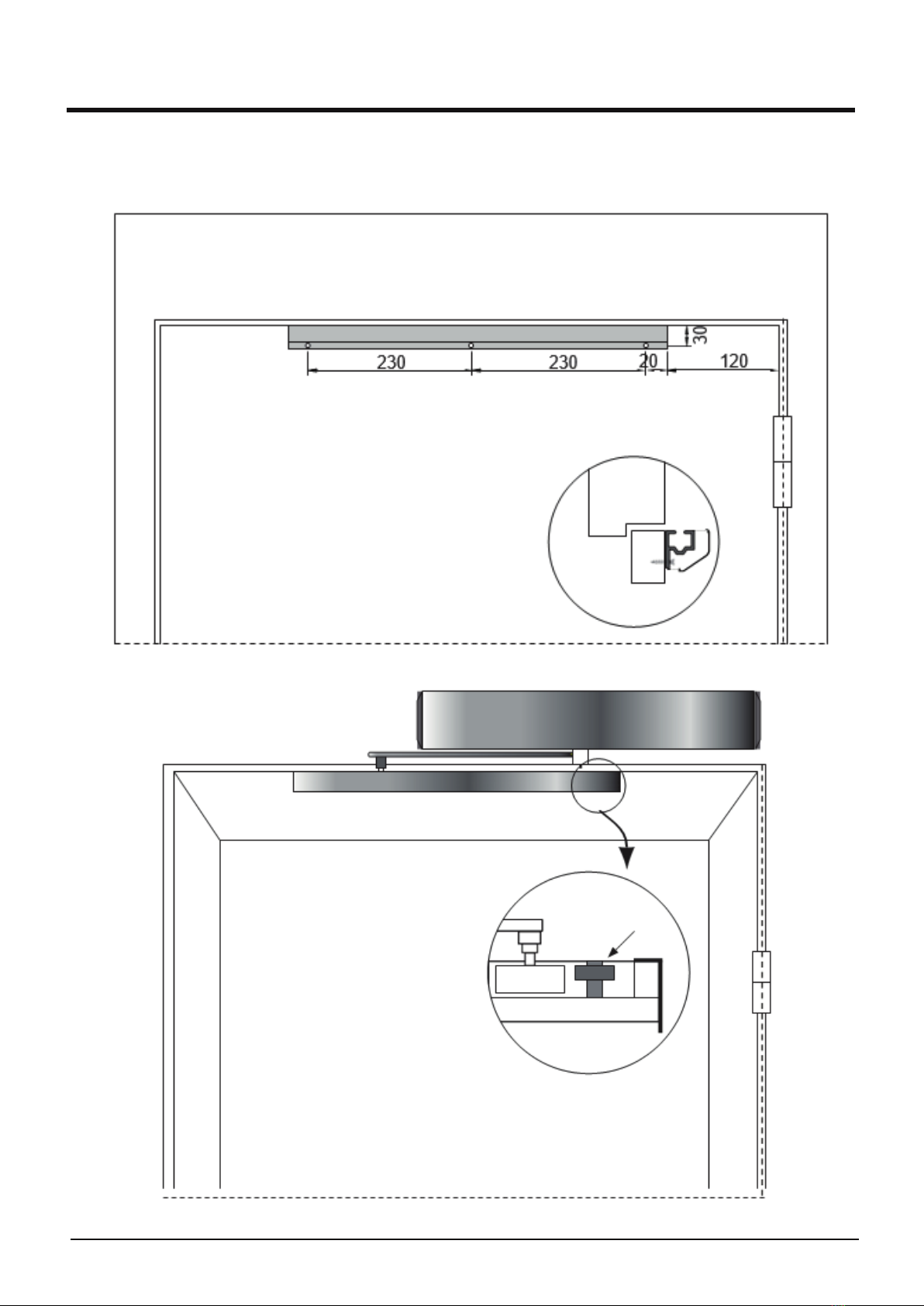
5.3 Installation of pull bar guider (Right position)
Installation of pull bar guider
Fix the pull bar on door leaf with
3 pcs self-tapping screw
Adjust the opening
angle by position
stopper.
Position stopper

11
5. Installation Step
5.3 Installation of pull bar guider (Left position)
Position
stopper
Adjust the opening
angle by position
stopper.
Installation of pull bar guider
120
20
Fix the pull bar on door leaf with
3 pcs self-tapping screw

12
5. Installation Step
5.4 Installation of pull bar for glass door
Tip: Ensure 25mm space for glass top to door frame bottom (Glass door installation).
500mm (19.68in) 130 mm
(5.12in.)
25mm (0.98in.)
81mm (3.19in.)
98mm (3.86in.)
mm (inches)
mm (inches)

13
5. Installation Step
5.5 Installation of push bar
5.5.1 Installation of push bar for glass door
Door leaf
Wall
mm (inches)
98mm (3.86in.)
93.5mm (3.68in.)
15
(0.59)
52
(2.05)
Adjust the push bar length with
the two screws according to the
door frame depth(L).
Automatic door right installation
L≤250mm
9.84 inches

14
5. Installation Step
5.6 Installation of extensions (Pull Arm)
5.6.1. 25mm (0.9843in.) short extension shaft
1. The standard installation height of the operator is 35mm (1.3779in.).
2. Short extension shaft installation height: 35mm+25mm=60mm
3. Mark a line from 60mm (2.3622in.) of the door head.
4. Uneven edges facing up.
5. The bottom plate goes flush with the bottom edge.
0.9843in.
1.3779in.
35mm (1.3779in.)
25mm (0.9843in.)
60mm (2.3622in.)

15
5. Installation Step
5.6 Installation of extensions (Pull Arm)
5.6.1. 25mm (0.9843 in.) short extension shaft
6. Tighten the screws to fix the bottom plate.
7. Hang up the machine.
8. Tighten the screws to fix the unit.
Screws
0.9843in.

16
5. Installation Step
5.6 Installation of extensions (Pull Arm)
5.6.1. 25mm (0.9843 in.) short extension shaft
9. Fix the pull arm.
10. Tighten the screws.
Screw
25mm
(0.9843in.)
Extension
Pull Arm
5.6.2. 50mm (1.9685 in.) long extension shaft
1. Long extension shaft installation height: 35mm+50mm=85mm
2. Mark a line from 85mm (3.3464in.) of the door head.

3. Follow the steps from 4 to 10 from the section 5.6.1.
5. Installation Step
5.6 Installation of extensions (Pull Arm)
5.6.2. 50mm (1.9685 in.) long extension shaft
17
Screw
50mm
(1.9685in.)
Extension
Pull Arm
35mm (1.3779in.)
50mm (1.9685in.)
85mm (3.3464in.)
Other manuals for VIS-440 Series
1
This manual suits for next models
2
Table of contents
Other Visionis Door Opening System manuals


Popular Door Opening System manuals by other brands


Assa Abloy
Assa Abloy SARGENT Powerglide 281 Series installation instructions

Nabco
Nabco GYRO TECH GT-1175 installation manual

Henderson
Henderson Evolve Glass SIM Kit Fitting instructions

Assa Abloy
Assa Abloy Norton UniTrol UNI-1600BC Series installation instructions

Digiway
Digiway DWPD102S Series installation manual

hager
hager 8300 Series quick start guide