TOPP M200 User manual
INSTRUCTIONS FOR
INSTALLATION AND USE
M200
STANDARD INSTALLATION
ORIGINAL INSTRUCTIONS
COD. 0P5711
VER. 00 REV.07.20
INDEX M200
2
instructions for installation
TECHNICAL DATA
PAG 3
GENERAL INFORMATION and SAFETY
PAG 4
PRELIMINARY OPERATIONS PAG 5 ARTICULATED ARM INSTALLATION
PAG 6
SLIDING ARM INSTALLATION
PAG 8
SLIDING ELBOW ARM INSTALLATION
PAG 10
ELECTRICAL CONNECTIONS
PAG 12
FIRST STARTUP
SELF LEARNING
PAG 17
DOUBLE LEAF INSTALLATION
PAG 18
ERRORS LIST
PAG 20-21

3
M200 -AUTOMATION FOR SWING DOORS
The Automation M200 for hinged doors is designed and produced in accordance to the European standard EN16005.The
automation is an electromechanical type designed for indoor installation only. The mechanical and electronic technology
guarantees safely the management and synchronization of swing doors with single and double panel. The automation
can be used in the pull inward conguration with sliding or elbow arm, and in the push outward conguration with normal
arm. The feature of the automation facilitates the installation process. The opening and closing movement of the door is
regulated by the software of the electronic circuit board, which manages the application of the forces and the continuity of
movement in the dierent congurations. The electronic board is a microprocessor type with keys directly on it for regu-
lation of the operating parameters and control of accessories such as activation radar, safety radar, dial selector, digital
switch, keys, etc. In compliance with the European standard EN 16005, low energy and full energy operating modes.
instructions for installation
M200
TECHNICAL DATA

GENERAL RECOMMENDATIONS
• This manual provides all instructions necessary for correct installation and maintenance of the automation. Topp srl is not liable for any damages to persons, animals and
property caused by failure to comply with these instructions.
• Before installing and using the automation the installer and user must read and thoroughly understand all parts of this manual.
• This manual is an integral part of the automation and must be kept by the installer, with all the enclosures, for future reference.
• The warranty is invalidated if use is made in any way not complying with the instructions and rules described in this manual, and if original parts, accessories, replacements
and control systems are not used.
• Topp srl reserves the right to improve and amend the manual and products described at any time and without notice.
• The information contained in this manual was written and checked with the maximum care; however, topp srl has no liability for any errors due to omissions or errors in
printing or transcription.
GENERAL SAFETY RULES
• The operators must be informed about the risks of accidents, the safety devices for the operators and the general accident-prevention rules contemplated by the interna-
tional directives and laws in force in the country of use of the automation. The operators’ conduct must always scrupulously comply with the accident prevention rules in
force in the country in which the automation is used.
• During handling and installation of the parts, the personnel shall be equipped with suitable personal protection equipment (PPE) so as to perform the works required under
safe conditions.
• To prevent injury and risks for the health of the workers, the maximum limits shall be applied for manual handling of loads, as provided in standard ISO 11228-1.
• Any unauthorized tampering or replacement of automation parts and any use of accessories or consumable materials dierent from the originals may cause a risk of ac-
cidents and relieves the manufacturer from any civil and criminal liability.
• For correct operation of the automation we recommend performing routine maintenance as indicated in paragraph 7 of this manual. Any operations of routine and special
maintenance that require even partial disassembly of the automation must be carried out only after disconnecting power to the automation.
• Do not remove or alter the plates and labels applied by the manufacturer on the automation and its accessories.
• It is strictly prohibited to hinder movement of the door and work near the hinges or mechanical moving parts (such as articulated or sliding arms).
• The manufacturer has no liability for any damage caused by improper or unreasonable use of the automation.
• When handling electronic parts always wear grounded antistatic conductive armbands as any electrostatic charges could damage the electronic parts on the boards.
• The electromechanical parts and electronic circuits necessary for control of the movement are protected by the aluminum casing.
• His device may be used by children at least 8 or older, and by persons with reduced physical, sensorial or mental faculties, or lacking experience, only under direct supervi-
sion or after they have received adequate instructions relative to its safe use.
• Children should not play with the device.
PROPER AND IMPROPER USE
• Automation M200 is designed and produced exclusively to operate (open and close) hinged doors and is intended for use in the residential, public and industrial sectors.
• It is strictly prohibited to use the automation for purposes other than those described, in order to guarantee the safety of the installer and user at all times and the eective
function of the automation.
• Automation M200 in low energy operating mode can be installed in places where the door is used by disabled, elderly or fragile persons or persons with limited motor
capacity, after performing the risk analysis and considering that the risk for this type of user is low.
INSTALLER
• Installation of the automation must be made exclusively by qualied technical personnel in possession of the professional requisites contemplated by the legislation in force
in the country of installation.
• The installer must be able to install the automation and start it, and to operate in the presence of electrical power inside electric cabinets and shunt boxes. He must be quali-
ed to make all the necessary adjustments of an electrical and mechanical nature.
• The use of parts, settings or processes not described in this document may cause electrical risks and/or hazards deriving from mechanical elements.
• The installer shall check for conformity to the directives and regulations in force regarding the safe use of motor-operated doors.
• After installing the automation, the installer shall perform an analysis of the risks and verify that the hinged door installation does not present risks in the points of crushing
or shearing and, if necessary, shall take adequate protective measures and apply the warning signs contemplated by the legislation in force to identify hazardous areas.
• Every installation shall display the identication of the motorized system in a clearly visible place.
• The installer shall also provide the owner with all the information relative to automatic, manual and emergency operation of the automation, and shall deliver the instructions
for use to contained in this manual to the user.
• He installer is the only person liable for erroneous installation and failure to comply with the instructions in this manual. The installer shall therefore respond on an exclusive
basis to the user and/or third parties for all damages to persons and/or property caused by erroneous installation.
• Topp srl is not liable for the adequacy and strength of the doors to be motorized.
RISK ANALYSIS BY THE INSTALLER
IN ANY CASE, THE INSTALLER HAS SOLE LIABILITY FOR THE COMPLETE SAFETY OF THE HINGED DOOR AFTER ANALYZING THE RISKS, AS WELL AS THE
RESIDUAL RISKS. ALL IN RESPECT OF THE LEGISLATION IN FORCE IN THE COUNTRY IN WHICH IT IS INSTALLED.
• The installer must evaluate and secure the system from risk of crushing, cutting, impact, trapping on the moving angles of closure and residual risks relative a door move-
ment..
• The installer must evaluate and secure the system from risk of crushing and cutting between the levers or between the levers, the gliding guide and residual risks relative
a leaf movement
USER
• The user must be able to use the automation under normal conditions and to perform simple operations of startup or reset of the automation after a possible forced inter-
ruption, through the use of the devices that serve for the purpose (program selector, digital switch, key switch, control buttons, etc.)
• The user must not open the casing or perform any other operations reserved for maintenance personnel or specialized experts. In case of breakdown or malfunction of the
door, the user shall only disconnect the circuit breaker and abstain from any other action or attempted repairs. use of the automation must be assigned exclusively to users
who comply with the instructions in this manual and in the manuals of the TOPP devices connected to it.
TECHNICAL ASSISTANCE
• For assistance, contact the installer or retailer..
RATING PLATE AND “CE” MARKING
• The “CE” marking certies the conformity of the machine to the essential health and safety requisites foreseen by the European product directives. It is formed of an ad-
hesive plate made from polyester, screen printed black, with the following dimensions: W=50mm - H=36mm. It should be applied by the installation technician in a clearly
visible position on the outside of the automation unit.
STANDARDS, LAWS, CODES AND REGULATIONS
• The latest versions of the common and country specic standards, laws, codes and regulations have to be observed.
RIGHTS RESERVED
• All information (text, drawings, diagrams, etc.) presented here is reserved. No part of this manual may be reproduced or disclosed in any way, with any means of reproduc-
tion (photocopies, microlm or others) without the written authorization of the Manufacturer.
• All rights regarding this manual of “Instructions for installation and use” remain the property of the Manufacturer.
M200
4
instructions for installation
GENERAL INFORMATION and SAFETY

5
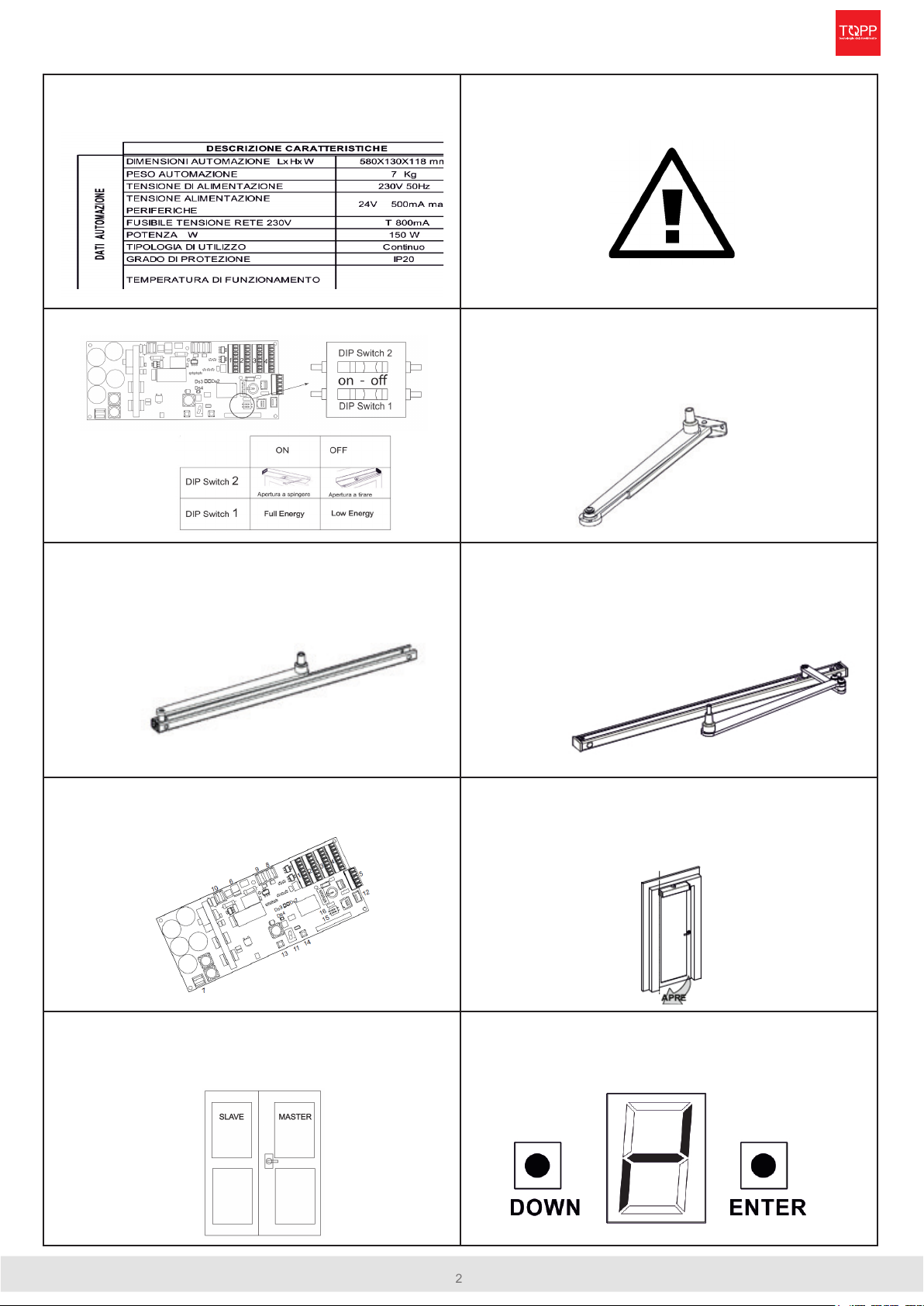
* required only in case of FULL ENERGY mode
Verify the sensor conguration directly in the sensors’ manual
SENSORS POSITIONING
REVERSE THE ELECTRONIC GROUP
ELECTRONIC BOARD DIP-SWITCHES SETTING
BEFORE STARTING THE INSTALLATION
Check the following points:
• The structure that will support the automation is suciently sturdy
• Surface on which the actuator bracket will be fastened is free of distortions.
• Care has been taken to eliminate protruding parts of the door
• Care has been taken to eliminate any sharp and/or pointed parts of the door
• The wing can move freely and without hindrance or friction.
• The wing is rigid and sturdy. The hinges are adequate and in good conditions.
• The door has a mechanical stop in opening (not supplied) (see Figure Ref. 1) 3 cm further
than the maximum desired opening position.
• The door closes rmly and smoothly.
• The power supply cables and the control cables for the sensors and/or related accesso-
ries have been prepared.
• If necessary, in case of installation with rotation axis (hinge) on the right side. invert the
electronic unit, as described below.
VERIFY
Before installation check the amplitude of passage, the direction of door opening, the side on
which the automation will be installed, the overlap of the architrave, the vertical space between
the automation and arm.
Orthogonality-parallelism of the enveloped surfaces.
instructions for installation
M200
PRELIMINARY OPERATIONS
M200
6
instructions for installation
ARTICULATED PUSHING ARM INSTALLATION
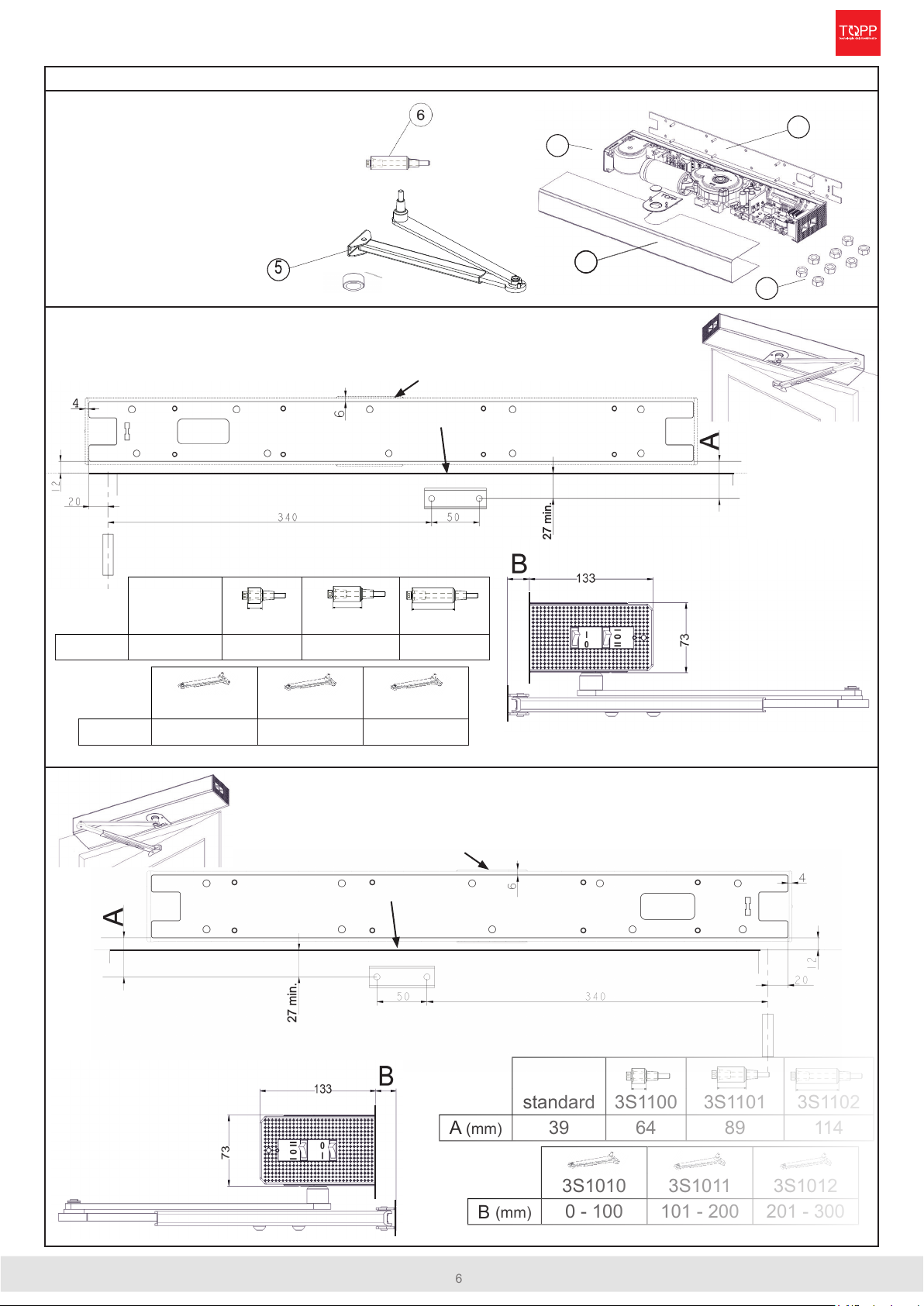
COMPONENTS
1- Cover, plastic cover plates and 4 xing screws
2- Automation M200
3- Fixing plate
4- Automation tting nuts
5- Articulated arm and extractor cap *
6- Axle extension and
corresponding screw (optional) *
* Supplied separately
Automation positioning with left hinge
Pay attention to the orientation of the xing plate,
to the lower edge of the frame and the axis of rotation of the door
Automation positioning with right hinge
Pay attention to the orientation of the xing plate, to the lower edge of
the frame and the axis of rotation of the door
1
1
2
3
4
lower end of the frame
xing plate
lower end of the frame
xing plate
The automation must be xed on the side of the wall which is opposite to the
hinges. The distance «A» varies according to the type of the Axls extension
used. See the table.
The automation must be xed on the side of the wall which is
opposite to the hinges. The distance «A» varies according to
the type of the Axls extension used. See the table.
automation external dimensions
automation external dimensions
standard 3S1100 3S1101 3S1102
A (mm) 39 64 89 114
3S1010 3S1011 3S1012
B (mm) 0 - 100 101 - 200 201 - 300
standard 3S1100 3S1101 3S1102
A (mm) 39 64 89 114
3S1010 3S1011 3S1012
B (mm) 0 - 100 101 - 200 201 - 300
7instructions for installation
M200
ARTICULATED PUSHING ARM INSTALLATION
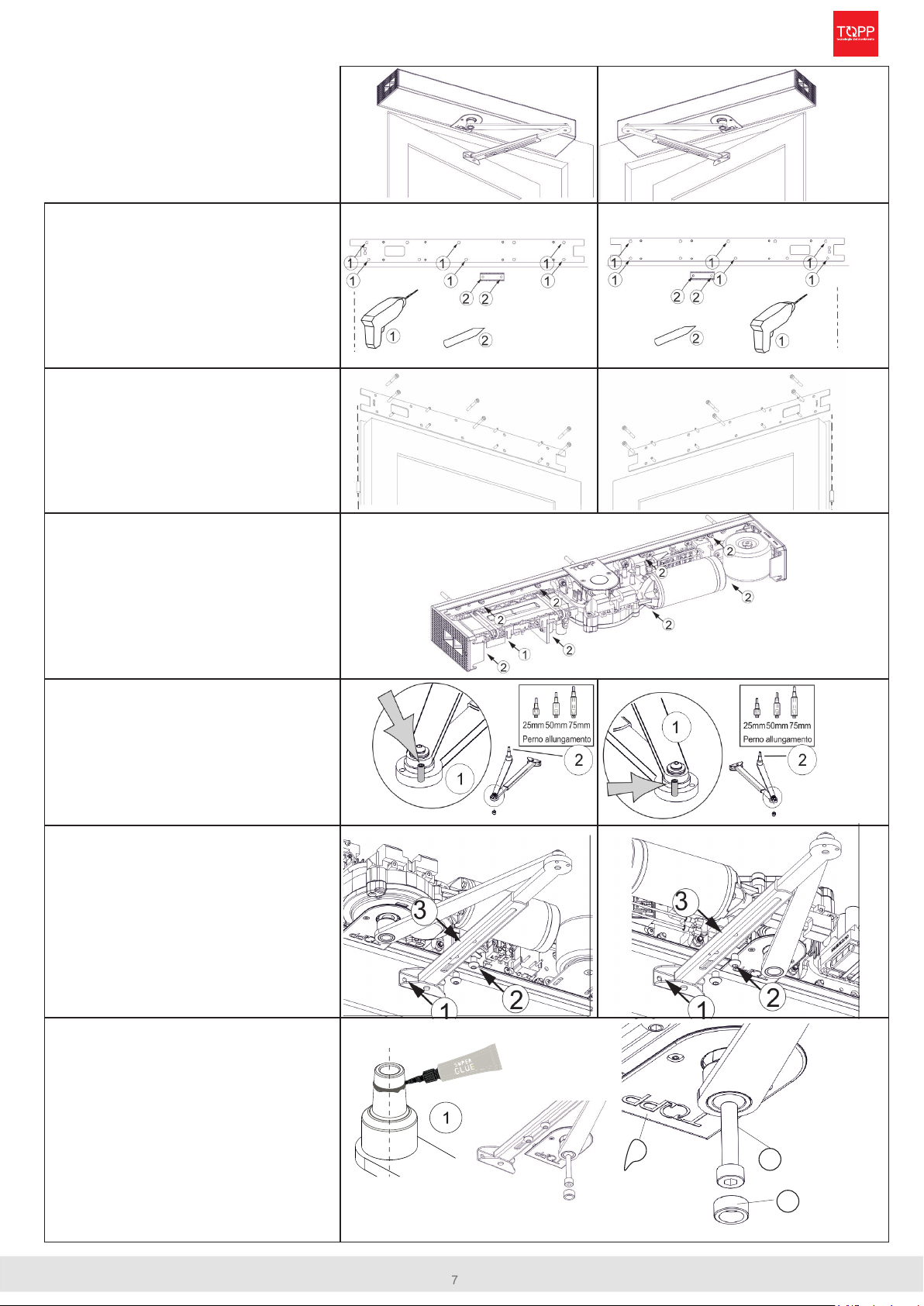
AUTOMATION INSTALLATION
M200 with articulated
pushing arm
DRILLING HOLES
1. With a suitable drill, make the 6 holes as
per the position specications and insert
the 6 anchors in the wall holes
2. Mark the 2 xing points for the arm
bracket
PLATE FITTING
1. Fasten the mounting plate with the xing
screws securely.
2. Prepare the input for the electrical wires
AUTOMATION FITTING
1. Position the electric wires inside the
automation.
2. Fit the unit and tighten the 8 nuts to
secure the automatio
ARM ASSEMBLY
1. Assemble the arm with the dowel as
shown in the gure
2. If the application required, insert the axle
extension
ARM ADJUSTMENT
1. Fix the arm bracket to the door with two
appropriate screws in the holes previ-
ously drilled
2. Loosen the two screws for the arm length
adjustment
3. Make sure the door is closed, position
the extendable lever of the arm at a
90°angle from the door, adjust the arm
length and tighten the two adjustment
screws
ARM FITTING
1. Apply the supplied glue to the upper part
on the outer conical surface of the pin,
making a circumference all around the
pin
2. Make sure the door is closed, Insert the
pivot pin of the arm in the housing on the
actuator, taking care to have previously
tted the plastic cover (ref.a)
3. insert the fastening screw of the arm in
the motor axis and tighten with torque
of 38Nm and screw the extractor cover
cap(ref. b) on the arm.
3
a
b

M200
8
instructions for installation
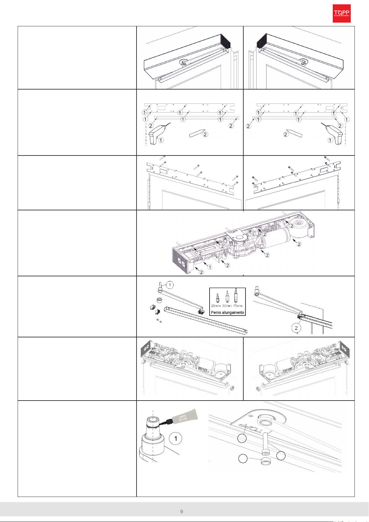
SLIDING PULLING ARM INSTALLATION
COMPONENTS
1- Cover, plastic cover plates and 4 xing screws
2- Automation M200
3- Fixing plate
4- Automation tting nuts
5- Sliding arm and extractor cap *
6- Axle extension and
corresponding screw (optional) *
* Supplied separately
Automation positioning with left hinge
Pay attention to the orientation of the xing plate,
to the door edge and the axis of rotation of the door
Automation positioning with right hinge
Pay attention to the orientation of the xing plate,
to the door edge and the axis of rotation of the door
1
1
2
3
4
door edge
xing plate
door edge
xing plate
automation external dimensions
automation external dimensions
standard 3S1100 3S1101 3S1102
A (mm) 55 80 105 130
3S1020
B (mm) 0 - 30
standard 3S1100 3S1101 3S1102
A (mm) 55 80 105 130
3S1020
B (mm) 0 - 30
The automation must be xed on the side of the hinges.
The distance «A» varies according to the type of the Axls
extension used. See the table.
The automation must be xed on the side of the hinges.
The distance «A» varies according to the type of the
Axls extension used. See the table.
9
AUTOMATION INSTALLATION
M200 with pulling sliding
arm
DRILLING HOLES
1. With a suitable drill, make the 6 holes as
per the position specications and insert
the 6 anchors in the wall holes
2. Mark the 2 xing points for the arm
bracket
PLATE FITTING
1. Fasten the mounting plate with the xing
screws securely.
2. Prepare the input for the electrical wires
AUTOMATION FITTING
1. Position the electric wires inside the
automation.
2. Fit the unit and tighten the 8 nuts to
secure the automatio
SLIDING GUIDE ASSEMBLY
1. If the application required, insert the axle
extension
2. Grease the runner, then t the guide in
the runner taking care to leave the two
larger holes on the outside.
SLIDING GUIDE FITTING
1. Fix the sliding guide with two appropriate
screws in the holes previously drilled
2. Fit the caps in the front holes
3. Fit the lateral caps of the guide
ARM FITTING
1. Apply the supplied glue to the upper part
on the outer conical surface of the pin,
making a circumference all around the
pin
2. Insert the pivot pin of the arm in the hous-
ing on the actuator, taking care to have
previously tted the plastic cover (ref.a)
3. Make sure the door is closed, insert the
fastening screw of the arm in the motor
axis and tighten with torque of 38Nm and
screw the extractor cover cap (ref.b) on
the arm
b
instructions for installation
M200
SLIDING PULLING ARM INSTALLATION
3
a
M200
10
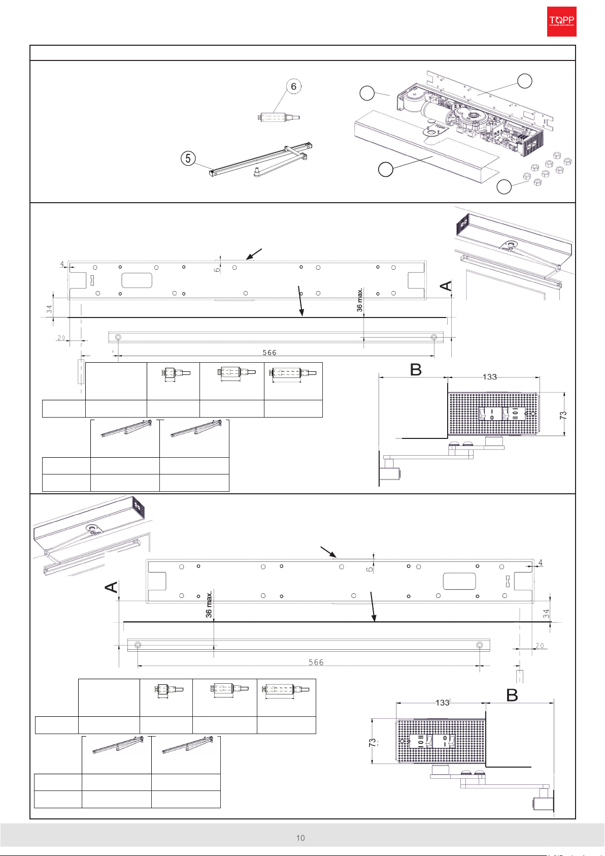
instructions for installation
SLIDING PULLING ARM INSTALLATION - ELBOW
COMPONENTS
1- Cover, plastic cover plates and 4 xing screws
2- Automation M200
3- Fixing plate
4- Automation tting nuts
5- Sliding elbow arm and extractor cap *
6- Axle extension and
corresponding screw (optional) *
* Supplied separately
Automation positioning with left hinge
Pay attention to the orientation of the xing plate, to the door
edge and the axis of rotation of the door
Automation positioning with right hinge
Pay attention to the orientation of the xing plate,
to the door edge and the axis of rotation of the door
1
1
2
3
4
The automation must be xed
on the side of the hinges. The
distance «A» varies according
to the type of the Axls exten-
sion used. See the table.
door edge
xing plate
door edge
xing plate
automation external dimensions
automation external dimensions
C
C
3S1030 3S1031
B (mm) 0 - 100 101 - 200
C (mm) 107,5 277
standard 3S1100 3S1101 3S1102
A (mm) 70 mm 95 mm 120 mm 145 mm
3S1030 3S1031
B (mm) 0 - 100 101 - 220
C (mm) 107,5 277
standard 3S1100 3S1101 3S1102
A (mm) 70 mm 95 mm 120 mm 145 mm
The automation must be xed
on the side of the hinges. The
distance «A» varies according
to the type of the Axls exten-
sion used. See the table.
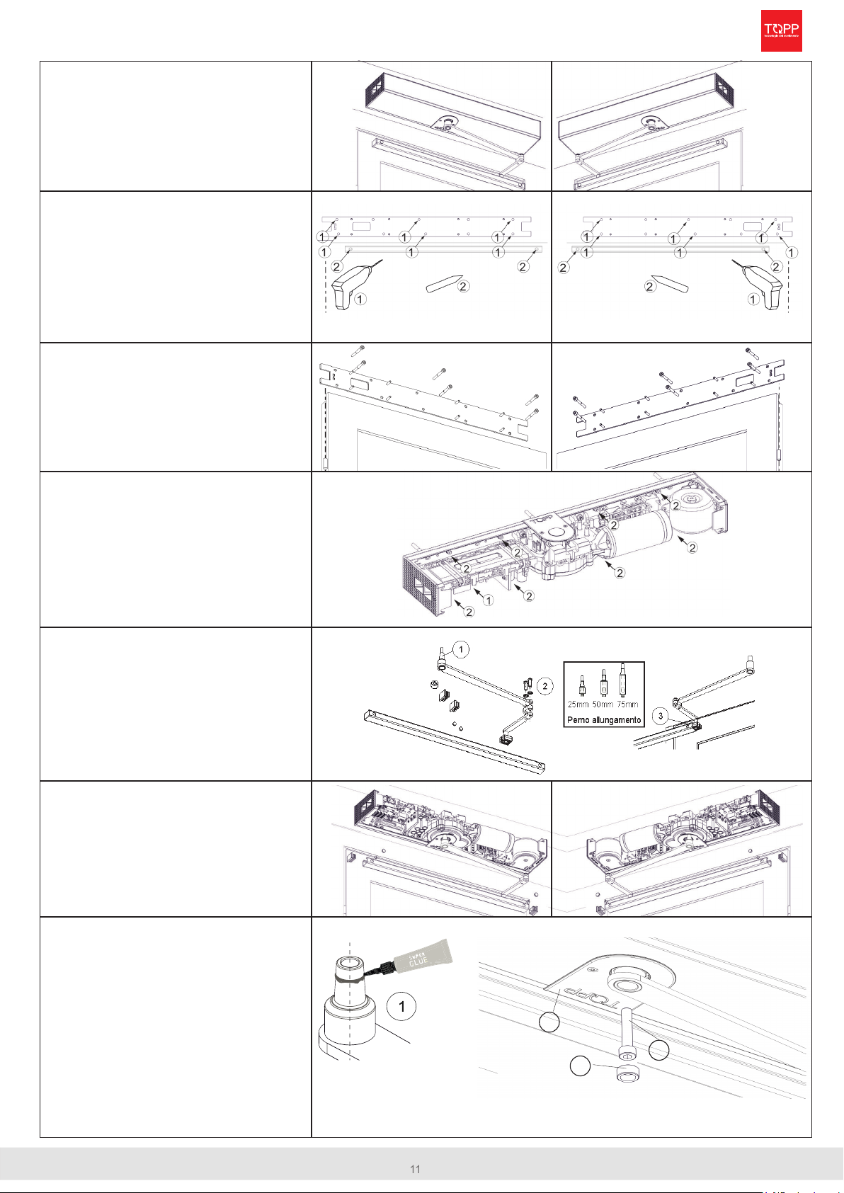
11
3
a
b
AUTOMATION INSTALLATION
M200 with pulling sliding
arm-elbow
DRILLING HOLES
1. With a suitable drill, make the 6 holes as
per the position specications and insert
the 6 anchors in the wall holes
2. Mark the 2 xing points for the arm
bracket.
PLATE FITTING
1. Fasten the mounting plate with the xing
screws securely.
2. Prepare the input for the electrical wires
AUTOMATION FITTING
1. Position the electric wires inside the
automation.
2. Fit the unit and tighten the 8 nuts to
secure the automatio
SLIDING GUIDE ASSEMBLY
1. If the application required, insert the axle
extension
2. Assemble the axle 90° elbow arm
3. Grease the runner, then t the guide in
the runner taking care to leave the two
larger holes on the outside.
SLIDING GUIDE FITTING
1. Fix the sliding guide with two appropriate
screws in the holes previously drilled
2. Fit the caps in the front holes
3. Fit the lateral caps of the guide
ARM FITTING
1. Apply the supplied glue to the upper part
on the outer conical surface of the pin,
making a circumference all around the
pin
2. Insert the pivot pin of the arm in the hous-
ing on the actuator, taking care to have
previously tted the plastic cover (ref.a)
3. Make sure the door is closed, insert the
fastening screw of the arm in the motor
axis and tighten with torque of 38Nm and
screw the extractor cover cap (ref.b) on
the arm
instructions for installation
M200
SLIDING PULLING ARM INSTALLATION - ELBOW

M200
12
instructions for installation
ELECTRICAL CONNECTIONS
BEFORE MAKING THE ELECTRICAL CONNECTION OF THE AUTOMATION, CHECK THAT:
• The main power supply connected to the automation must comply with the requisites contemplated by the legislation
in force in the country of installation, and must have the technical characteristics indicated in tab.2- cap.2.5 and on the
rating plate, as well as the “CE” seal of approval.
• Electrical connection of the automation must be made exclusively by skilled, qualied technical personnel in possession
of the professional requisites contemplated by the legislation in force in the country of installation, who shall issue the
client a declaration of conformity of the connection and/or installation made.
• The main power supply connected to the automation shall be provided with an omnipolar magneto-thermal dierential
30mA switch with aperture of at least 3 mm between the contacts. This device shall be installed in the power supply sy
tem in accordance with the requisites contemplated in the legislation in force in the country of installation.
• The power line must be protected against earth leakage and the installation shall provide a grounding line longer than
the power line so that if pulled, the ground line is the last to go taut.
• Before making electrical connections make sure there is no power on the mains.
• The recommended power cables are as follows: H05VV-F 3X0.75, H05RN-F 3X0.75, self-extinguishing types for electrical
connections. For wiring of the analogue selector we recommend using a multipole 8 x 0.5 type LI-YY.
• The installer shall take care to secure the power cable stably inside the automation. The cable will be inserted in the main
entry hole of the automation with its sheath.
• Limit stripping of the primary sheath of the cable to the distance necessary for connection to the terminal
• Before making the electrical connection of the automation, check that the power cable is undamaged.
• The hole in the substratum for passage of the power cable shall be made without rough or sharp edges or points that
could damage the cable.
• Connection to the power mains in the portion outside the automation shall be made on an independent channel, separate
from the connections to the control and safety devices.
• Any type of electrical material (plug, cable, clamps, etc.) used for connection must be suitable for the purpose, marked
“CE” and must comply with the requisites envisaged by the legislation in force in the country of installation. For wiring,
use cable with double insulation up to the immediate vicinity of the connectors.
• Whenever the operator is powered up with battery only, and whatever is the operation mode set, to perform a complete
power o, press and hold for 5 seconds near/reset button.
POWER SUPPLY
13 instructions for installation
M200
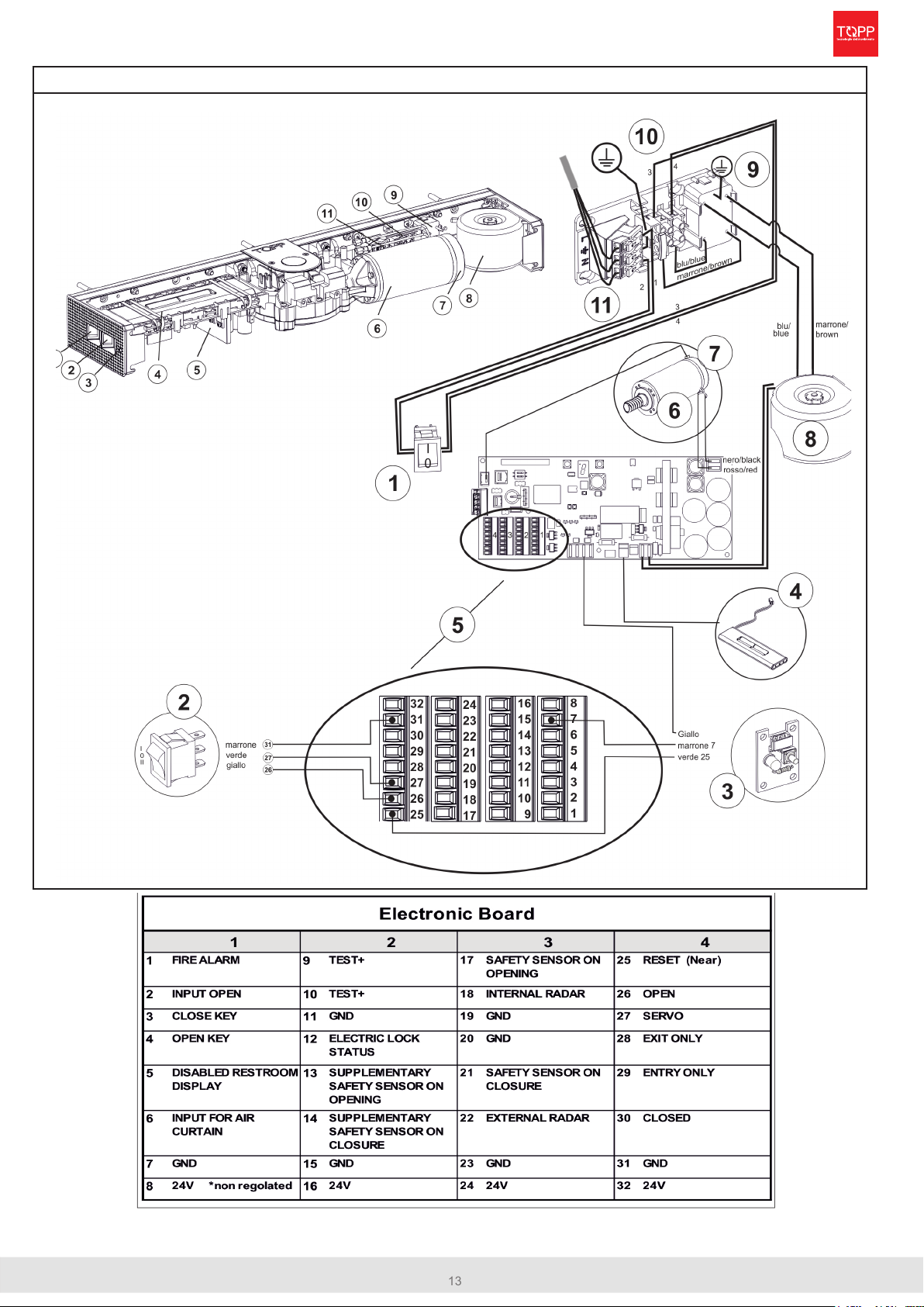
ELECTRICAL CONNECTIONS
PRE-WIRED ELECTRIC CONNECTIONS - POWER SUPPLY CIRCUIT
1 ON-OFF Switch
2 Function selector
3 Led signal/ Near
4 Battery
5 Electronic board
6 Motor
7 Encoder
8 Transformer
9 Filter
10 Fuse
11 Power supply connection
M200
14
instructions for installation
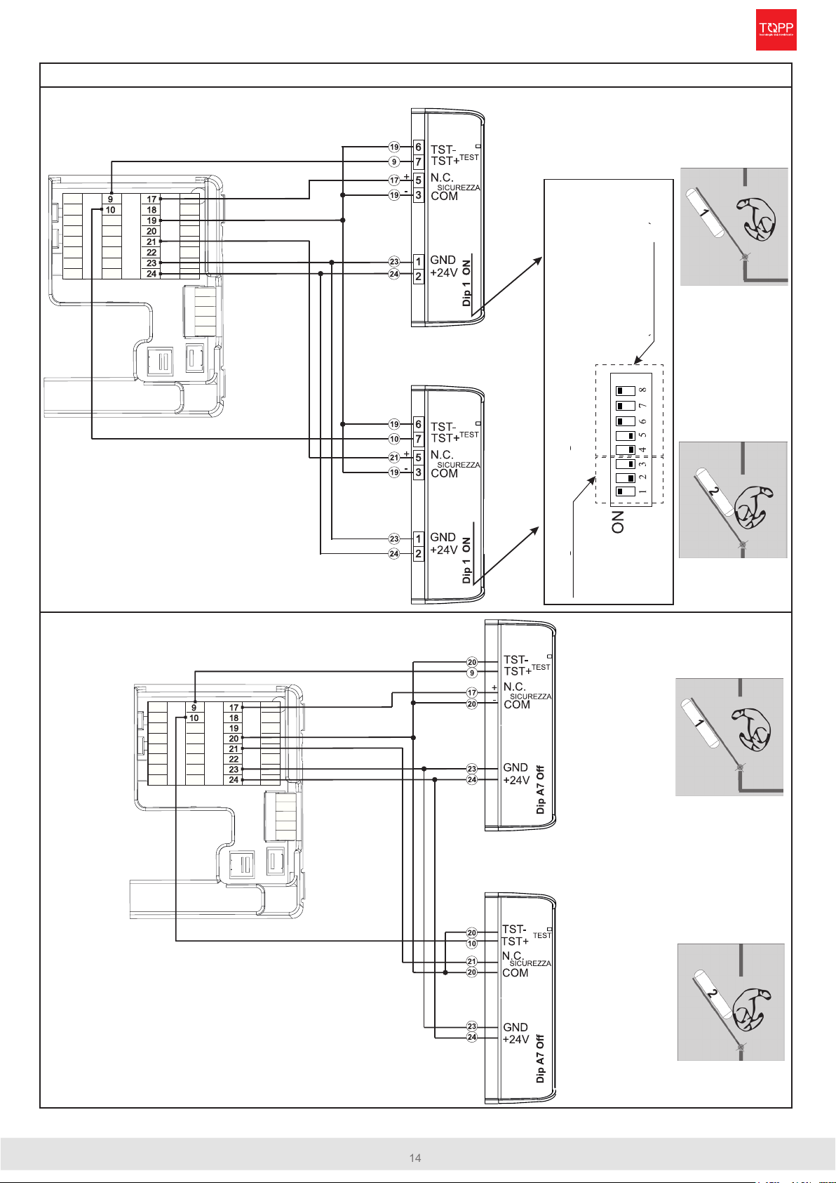
ELECTRICAL CONNECTIONS - SAFETY SENSORS
SAFETY SENSORS CONNECTION, IF THEY ARE PRESENT
CONNECTION OF IS6 TOPP SAFETY SENSOR
HOTRON SSS-5
CONNECTION OF OPTEX SAFETY SENSORS
OPTEX AO EDGE T
OPENING SAFETY SENSOR
CLOSING SAFETY SENSOR-
Modify these values if you want
to reduce or enlarge the de-
tection area (see sensor manual)
Congure as in gure-
OPENING SAFETY SENSOR
CLOSING SAFETY SENSOR

15 instructions for installation
M200
ELECTRICAL CONNECTIONS - SAFETY SENSORS
SUPPLEMENTARY SAFETY SENSORS CONNECTION, IF THEY ARE PRESENT
CONNECTION OF IS6 TOPP SUPPLEMENTARY SAFETY SENSOR-
HOTRON SSS-5
CONNECTION OF OPTEX SUPPLEMENTARY SAFETY SENSORS
OPTEX AO EDGE T
SUPPLEMENTARY OPENING
SAFETY SENSOR
SUPPLEMENTARY CLOSING
SAFETY SENSOR
Modify these values if you want
to reduce or enlarge the detection
area (see sensor manual-
Congure as in gure-
SUPPLEMENTARY OPENING
SAFETY SENSOR-
SUPPLEMENTARY CLOSING
SAFETY SENSOR
M200
16
instructions for installation
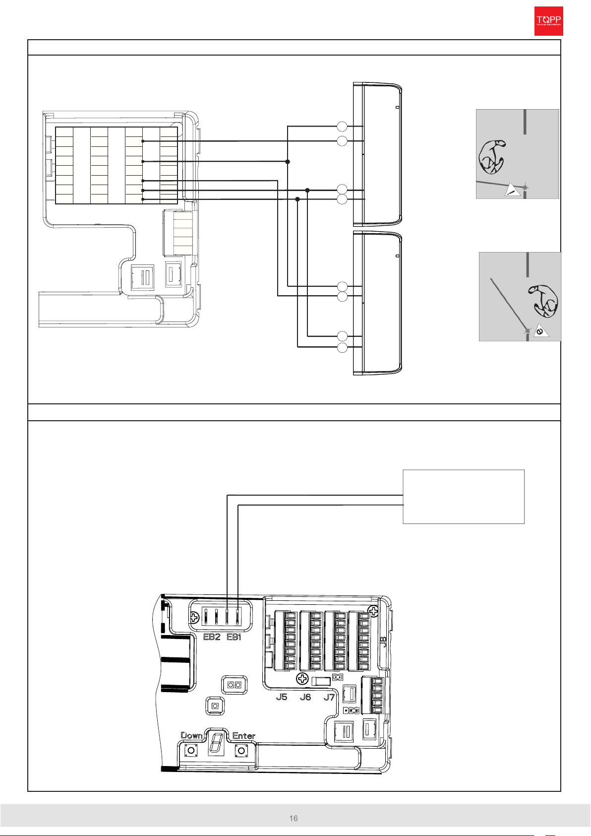
ELECTRICAL CONNECTIONS - RADAR
1
1
7
7
1
1
8
8
1
1
9
9
1
1
2
2
2
2
0
0
1
1
3
3
2
2
1
1
1
1
4
4
2
2
2
2
1
1
5
5
2
2
3
3
2
2
4
4
GND
+24V
ATTIVAZIONE
N.O.
GND
+24V
COM
ATTIVAZIONE
N.O.
COM
RADAR INTERNO
ATTIVAZIONE
24
23
18
20
20
22
23
24
RADAR ESTERNO
ATTIVAZIONE
Parametro D= 0 oppure
D=2
D=4
Elettroserratura
+
-
ACTIVATION SENSORS CONNECTION, IF THEY ARE PRESENT
CONNECTION OF ELECTRIC LOCK
If the electric lock is present, congure the parameters: 127,132,133.
See page 21 for programming
iINTERNAL ACTIVATION SENSOR
EXTERNAL ACTIVATION SENSOR
ELECTRIC LOCK
17 instructions for installation
M200
Sensore Sicurezza
in chiusura
Sensore Sicurezza
Supplementare
in chiusura
Sensore Sicurezza
Supplementare
in apertura
Sensore Sicurezza
in apertura
FIRST STARTUP - SELF LEARNING
SYSTEM CHECK-UP
Before performing the start-up operation check that the automation is correctly installed, the door is closed and that the
DIP switches are correctly positioned as described on page 5.
If the installation includes the DS2S digital selector, follow the instructions for operation and start-up included with the
selector.
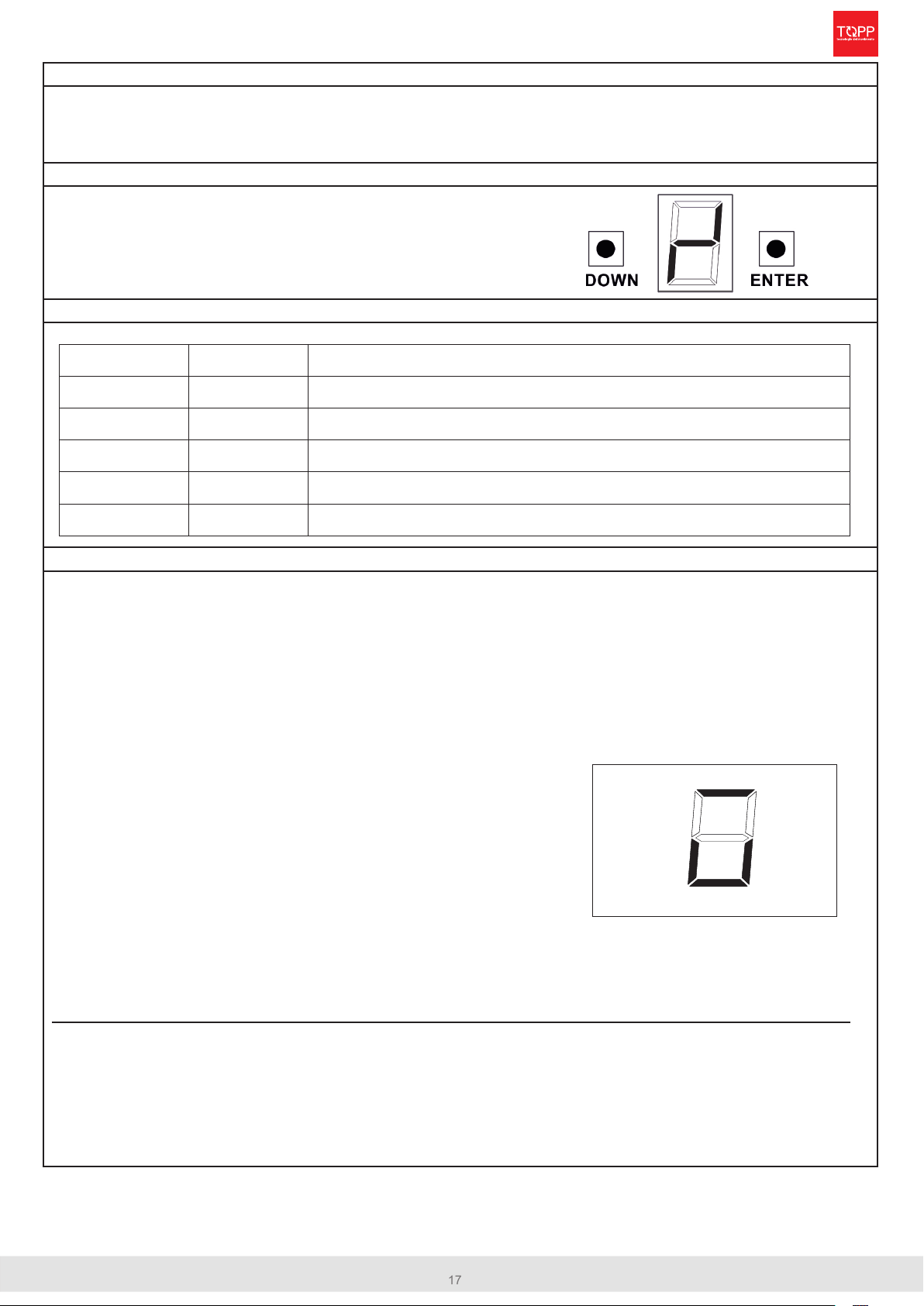
GIVE POWER TO THE AUTOMATION BY POSITIONING THE POWER SWITCH IN "ON"
The electronic board in its native state
shows on the display the following
ashing symbol:
CHECK THE CONFIGURATION OF THE MAIN PARAMETERS
If your installation diers from those parameters, follow the programming instructions on page 21
START THE SELF LEARNING PROCESS
• Clear people or things o of the safety sensors detection areas. There must be no obstacles in the door movement
area during the whole procedure.
• Start the self-learning procedure by pressing both keys <ENTER> and <DOWN> on the automation for 5 seconds.
The display shows the word “RESET” blinking.
• The automation acknowledges the presence of the safety sensors, controls that the door is closed and starts a
cycle by opening 70°.
• At this point, move the door manually to maximum opening position desired.
!!! PERFORM ONLY THE OPENING MOVEMENT OF THE DOOR: IN THE EVENT OF WRONG
POSITIONING,REPEAT THE PROCEDURE FROM THE BEGINNING !!!
Press the <ENTER> button on the board to conrm the maximum
opening point.
After 20 seconds, the door closes and goes back to normal operation.
If the self-learning procedure has been completed successfully, the
detected sensors are shown on the display (as in the example in the side)
to allow the installer to verify the correct acquisition of the sensors.
If an error occurs, check the error map on page 20.
In Full Energy it is essential that at least the two main safety sensors are installed, the lack of even one of the sensors
causes an error. The safety sensors are monitored and therefore must respond when the test signal is enabled. In
this way the electronics recognizes the sensors that respond to the test signal as present. If non-monitored sensors are
used, before performing the self-learning procedure, the installer must change the parameter 105 (for programming
see pages 21) of the sensor logics to disable the test.
For programming remote controls (up to 8):
1.Press and hold the <DOWN> key for 5 seconds, the display shows the word “RADIO” blinking on the 7-segment display.
2.If you are using the 4-channel Topp TS1S remote control, press the second button (closed function). To conrm that the remote control
has been memorized, the blinking word “RADIO” will no longer be displayed.
For removing: memorized remote controls
1.Press and hold the <DOWN> key for 5 seconds, the display shows the word “RADIO” blinking on the 7-segment display.
2.Press and hold the “DOWN” key for a further 5 seconds, all connected remote controls are cleared. To conrm that all programmed remo-
te controls have been removed, the blinking word “RADIO” will no longer be displayed.
A
b
C
d
E
2
3
1
2
1
Radar logics: N.O. with the inside safety sensor in closure which commands door opening
VALUE
Door weight 75 Kg
Door width 800 mm
Architrave depth 0 mm
Safety sensors logic: N.C. with active high test
DESCRIPTION
-parameter 101
-parameter 102
-parameter 103
-parameter 104
-parameter 105
PARAMETER
Safety sensor in closing-
Safety sensor in opening-
Supplementary
Safety sensor
in opening-
Supplementary
Safety sensor
in closing-

M200
18
instructions for installation
DOUBLE LEAF INSTALLATION
DOUBLE LEAF OPERATION
Perform the mechanical installation and the electric wiring assuming the two leaves would be independent, following page
6 in presence of articulated arm or page 8 sliding arm or page10 elbow arm.
The Double leaf operation has a MASTER and a SLAVE leaf. The MASTER leaf is the rst one to OPEN.
ADDITIONAL CONNECTIONS AND SPECIFIC PARAMETERS SETTING
• Connect the MASTER and SLAVE boards
by following the wiring diagram on the right
• Make sure the operators are installed cor-
rectly and the door leaves are in CLOSE
position
• Set parameter as 1 on MASTER and 2
on SLAVE
• Set independently for each wing the pa-
rameters 101,102,103,104,105 (related to
weight, width, wall depth, sensors logic for
activation and safety) as shown in page 21
• Following the instructions on page 17, per-
form the learning process of the MASTER
door leaf rst and the SLAVE door leaf
later; during the SLAVE door leaf learning
process, the MASTER one will automati-
cally move to OPEN position. +24V
Seriale B
GND massa
Seriale A
1
2
3
5
1
2
3
4
5
1
2
3
4
5
SCHEDA ELETTRONIC A
MASTER
SCHEDA ELETTRONIC A
SLAVE
MASTER BOARD
SLAVE BOARD-
*
* view disabled button connection Servo Assisted Manual Opening page 29
SLAVE LEAF
MASTER LEAF

19 instructions for installation
M200
MAINTENANCE - PARTS REQUEST - DEMOLITION - NEAR
MAINTENANCE
A regular maintenance is required to ensure the correct operation of the automation, this maintenance activity may be
carried out either by TOPP, in accordance with a specic agreement made with the user, or by the installation technician
or by other competent and qual-ied technical personnel in possession of all legal requirements.
All works of maintenance, except functional alterations, must be carried out with the door closed and the power discon-
nected (including the emergency battery).
The recommended periodical routine maintenance should include at least the following activi-ties:
Every 3 months:
If present, check the battery charge level:
1) Turn on automation
2) Enter programming mode and congure parameter 110: with a value other than “0”
3) Exit programming and disconnect the 230V power supply to the automation.
In the event that the leaves do not open, the emergency batteries must be replaced.
Every six months:
• Check the door glide and eliminate any friction; make sure the hinges are in good condition and not worn;
• clean the radar and safety sensors with non-abrasive detergents;
• check that there are no blind spots in the vicinity of the moving doors which might not be detected by the radar and
safety sensors;
• check the stability of the automation and secure fastening of all the screws: actuator - arm;
• check the connections and electric wiring;
• power the automation and check the stability of the door, making sure that the movement of the panels is smooth
and friction-free; disconnect the power and check that the emergency batteries open the door completely on the
passageway;
• if worn, change the arm and other worn parts.
Every 24 months:
• replace the emergency battery system (remember to disconnect the power).
• The duration of the battery back is aected by the environmental and functional conditions of the automation.
ACCESSORIES AND PARTS ON REQUEST
Always use original spare parts and accessories. Non-original parts could endanger safe and ecient operation of the
automation. Original spare parts and accessories must be ordered exclusively from the dealer or manufacturer, commu-
nicating the type, model, serial number and year of construction of the automation.
DEMOLITION
Demolition of the automation must be carried out in respect of the legislation in force on the subject of environmental
safeguards. The mandatory rst step is to proceed with dierentiation of the parts of the automation according to the dif-
ferent types of material.
The emergency battery must be removed from the device before disposal (remember to disconnect power) because the
battery pack contains hazardous substances that must be eliminated safely.
“NEAR” Function
It performs a re-alignment of the operator in case of upcoming errors
To activate the procedure press and hold for 2 seconds the “NEAR” button on the analog selector,
To activate the procedure use the dedicsted command on the DS2S digital selector,
To activate the procedure press and hold for 2 seconds the “CLOSE” buttin of the TS1S wireless function selector
OPERATOR RESTART IN CASE OF POWER CUT (NEAR)
Whenever the operator is switched o (voluntarily or after a power cut), once it is restarted, a soft reset “NEAR” procedure
is automatically performed by following the setting of the parameter 117 (default value “0” ) the automation self-realigns
with the door in closed position.
If the automation was pre-set in CLOSE mode, the NEAR (re-alignment) will be performed only at the rst operation
(through impulse) or once the door mode will be changed from CLOSE. The re-alignment will follow the setting of pa-
rameter 117.

M200
20
instructions for installation
LIST OF ERROR MESSAGES AND NOTICES
Table of contents
Other TOPP Door Opening System manuals


Popular Door Opening System manuals by other brands


Eco
Eco TS-50 Assembly instruction

SAINT-GOBAIN
SAINT-GOBAIN SEVAX MINOS+ manual

Dormakaba
Dormakaba ED100 installation instructions

CornellCookson
CornellCookson FS-500EP Series Installation instructions and operation manual

Record
Record system 20 RED Series user manual

ECO Schulte
ECO Schulte EF BG Assembly instruction