Fort Vale Super Maxi 0R3/006 Series User manual

®
FORT VALE
Maintenance Manual
Super Maxi Relief Valve
AAR Specification
0R3/XXXX006X Series
MM050_REV01 03.05.18
This is an uncontrolled copy and will not be updated automatically.
Please refer to Fort Vale periodically for document revisions.

BEFORE ATTEMPTING DISASSEMBLY OR REMOVAL OF ANY FORT VALE
COMPONENT, ALWAYS DEPRESSURIZE AND DRAIN ANY PIPING SYSTEMS.
Prior to commencing any remedial work :
Prior to handling the valve, ascertain the last product carried and ensure that the valve has been correctly decontaminated.
Obtain a Material Safety Data Sheet for the last product carried and observe all the Health and Safety advice, particularly
with regards to P.P.E. (Personal Protection Equipment)
personnel
Servicing of valves should be conducted by a “Qualified Person”
The term “qualified person” relates to a person familiar with the installation, assembly, operation, applications and
limitations of the component. The person should have the qualifications corresponding to their responsibilities, such as
instruction and awareness to comply with all operational, regional and in-company regulations and requirements.
Limitations of use/Mis-use
Please observe the maximum allowable working pressure and the minimum/maximum allowable temperature range and
ensure that the valve is not operated outside these limitations. Use/operation outside these limits is at the risk of the user
and Fort Vale shall bear no responsibility for such actions.
Servicing
Fort Vale components are manufactured for longevity under normal and compatible working conditions. It is the
responsibility of the user to take into account the working conditions of the valve and to implement a regular service
schedule based upon individual circumstances. In addition, a thorough visual inspection of the valve should be made at
regular intervals to check for correct operation and signs of corrosion. It must be noted that working at extremes of
temperature and/or pressure will reduce the operational life of the valve between services.
AFTER ANY REMEDIAL WORK, ENSURE THAT THE VALVE IS LEAK TESTED PRIOR TO RETURNING TO SERVICE.
During service or testing, if any problem arises that cannot be resolved with the use of this Maintenance Manual, please
contact Fort Vale for further advice and assistance.
Risk assessment and hazard assessment
Fort Vale recommends a full and comprehensive risk and hazard assessment in accordance with national or local
legislation prior to servicing a valve. Not all service environments are the same and basic instructions may need to be
incorporated into the safe procedures for use of the end user. See examples below:
- Correct use of personal protection equipment when working with compressed gases
- Correct use of personal protection equipment when working with low temperature components
- Correct use of personal protection equipment when working with heavy components and the use of lifting equipment
- Training and competence of conducting pressure testing
Important Safety Notice
OPIN41 REV00-29.07.13
© Fort Vale Engineering Ltd. 2013
Page 1
Fort Vale Engineering Limited ·
·www.fortvale.com
Calder Vale Park, Simonstone Lane, Simonstone, Burnley, Lancashire BB12 7ND, U.K.
Tel : +44 (0)1282 687100 · Fax : +44 (0)1282 687110 · Email : [email protected]
Maintenance Safety Advice
®

Super Maxi Relief Valve - AAR Specification
CAUTION: The Super Maxi relief valve is a spring-loaded device. Exercise caution during maintenance and wear
the appropriate PPE.
Part number(s : 0R3/XXXX006X
Manual Contents
Tools Required
13mm/ ” A/F spanner & torque wrench
38mm/1 ” A/F spanner & torque wrench
Rocol® lubricant
Thread adhesive (eg. Loctite® 243)
Scribe
3/32” hex key
Hammer
Pillar drill - 4mm (No. 22) drill, 3/16”BSW tap
Bench press (1 tonne minimum)
Pressure test rig
Proprietary Tools Required - available from Fort Vale
Nylon lifting spacer - FIX/A/0035
Cap tightening tool - FIX/A/0034
Pressure adjustment tool - FIX/A/0015/23
Consumable Parts Required - available from Fort Vale
Pressure O ring - part number varies according to seal material. Please see data sheet USREL148 for details.
Always ensure that the seal material is compatible with the cargo and operating conditions.
Further components may be required, subject to wear and condition. Damaged, worn or corroded parts should
always be replaced with new parts. Please contact Fort Vale for part numbers and further advice if necessary.
Chapter 1 Complete Disassembly
Chapter 2 Complete Assembly
Chapter 3 Pressure Testing & Adjustment
Appendix USREL147 & USREL148 - Data Sheet
USREL185 - Part Number Breakdown
MM050_REV01© Fort Vale Engineering Ltd. 2018

THIS PAGE IS INTENTIONALLY BLANK
MM050_REV01© Fort Vale Engineering Ltd. 2018

Super Maxi Relief Valve - AAR Specification
Chapter 1
Super Maxi Relief Valve
Disassembly Procedure
This chapter covers complete disassembly of the valve.
N TE:
Depending upon the reason for service, every step may not be required.
Damaged, worn or corroded parts should be replaced with new.
All seals, gaskets and O rings should be replaced with new, unless
otherwise stated.
MM050_REV01© Fort Vale Engineering Ltd. 2018 Page 1

Super Maxi Relief Valve - AAR Specification
Step 1. Identify the valve. The part number will be
laser marked on the cap. If in doubt, contact Fort
Vale.
Step 2. Note that the cap is retained by an anti-
tamper screw filled with lead shot.
Step 3. Use a 4mm No. 22) drill and drill out the
lead shot and grubscrew. This will unlock the cap
from the body.
Step 4. Clean the hole using compressed air.
Caution: Wear appropriate eye PPE.
Step 5. Use a scribe to detach the stainless steel
plug.
Step 6. Remove the stainless steel plug.
MM050_REV01© Fort Vale Engineering Ltd. 2018 Page 2

Super Maxi Relief Valve - AAR Specification
Step 7. Select the nylon lifting spacer FIX/
A/0035) - dimensions as above.
Step 8. Locate the nylon lifting spacer FIX/
A/0035) onto a bench press. A minimum 1 tonne
press is required.
Step 9. Locate the valve onto the spacer. Ensure
that the body flange is located centrally.
Step 10. Select the cap tightening tool FIX/
A/0034). Locate the two pins on the tool into the
two blind holes on the cap.
Step 11. Ensure that the cap tightening tool is
located squarely on the cap.
Step 12. Apply pressure on the cap tightening
tool until the spring is compressed enough to allow
the valve body to rotate. Rotate the body
clockwise until it is disengaged from the cap.
WARNING: The valve is under spring load.
Exercise caution and wear the appropriate PPE.
MM050_REV01© Fort Vale Engineering Ltd. 2018 Page 3

Super Maxi Relief Valve - AAR Specification
Step 13. Slowly retract the ram to allow the spring
to decompress. WARNING: The valve is under
spring load. Exercise caution and wear the
appropriate PPE.
Step 14. When the spring is completely
decompressed, retract the ram so that the valve
can be disassembled.
Step 15. Remove the cap tightening tool. Step 16. Remove the cap. Inspect the cap for
damage. If damaged, contact Fort Vale.
Step 17. Remove the springs. Inspect the springs
for damage or corrosion. If damaged, contact Fort
Vale.
Step 18. Remove the pressure plate assembly.
MM050_REV01© Fort Vale Engineering Ltd. 2018 Page 4

Super Maxi Relief Valve - AAR Specification
Step 19. Remove the valve body. Inspect the
body for damage or corrosion. Pay particular
attention to the pressure plate sealing face and the
gasket sealing face. If damaged, contact Fort
Vale.
Step 20. Use a 13mm ½") spanner to loosen the
5/16" UNF nut on the pressure plate assembly.
Step 21. Remove the 5/16" UNF stud and nut. Step 22. Use a 13mm ½") spanner to remove the
5/16" nut from the stud. If the nut has seized, use
2x 5/16" nuts as shown to prevent damage to the
thread: Clamp nut 1 in a vice and tighten nut 2.
Unlock nut 3 by rotating it clockwise and counter-
clockwise. Remove nut 3.
Step 23. Use a wire brush to clean any adhesive
residue from the stud. Inspect the thread on the
stud. If it is damaged, replace the stud.
Step 24. To separate the inner and outer
pressure plate, insert a rod that is smaller in
diameter than the hole in the inner pressure plate.
Gently tap the rod with a hammer to disassemble
the inner pressure plate. Remove the retaining
washer.
MM050_REV01© Fort Vale Engineering Ltd. 2018 Page 5

Super Maxi Relief Valve - AAR Specification
Step 25. Inspect inner pressure plate and the
washer for damage or corrosion. If damaged,
contact Fort Vale.
Step 26. Remove the O ring and discard. Inspect
the outer pressure plate for damage or corrosion.
If damaged, contact Fort Vale. Disassembly is now
complete.
MM050_REV01© Fort Vale Engineering Ltd. 2018 Page 6

Super Maxi Relief Valve - AAR Specification
Chapter 2
Super Maxi Relief Valve
Assembly Procedure
This chapter covers complete assembly of the valve.
NO E:
Depending upon the reason for service, every step may not be required.
Damaged, worn or corroded parts should be replaced with new.
All seals, gaskets and O rings should be replaced with new, unless
otherwise stated.
MM050_REV01© Fort Vale Engineering Ltd. 2018 Page 7

Super Maxi Relief Valve - AAR Specification
Step 27. Clean all pressure plate components
and inspect for damage or corrosion. If damaged,
contact Fort Vale.
1. 5/16"UNF nut; . Retaining washer;
3. 5/16"UNF x 30mm stud; 4. O ring;
5. Outer pressure plate; 6. Inner pressure plate.
Step 28. Apply thread adhesive to the thread of
the inner pressure plate.
Step 29. Locate the 5/16" UNF stud and tighten. Step 30 It is important to fully tighten the
assembly: Clamp the stud in a vice - take care not
to damage the thread. Tighten the pressure plate.
Remove the assembly from the vice.
Step 31. Locate a new O ring into the outer
pressure plate seal groove. Ensure that the O ring
is fully located around its circumference.
Step 32. Assemble the outer pressure plate onto
the inner pressure plate assembly.
MM050_REV01© Fort Vale Engineering Ltd. 2018 Page 8

Super Maxi Relief Valve - AAR Specification
Step 33. Ensure that the O ring is uniformly
located.
Step 34. Locate the retaining washer.
Step 35. Apply thread adhesive to the thread of
the stud and locate the nut.
Step 36. Use a 13mm (½") torque wrench to
tighten the nut to a torque of 0 Nm (15 Lb.ft)
Step 37. Assembly of the pressure plate is
complete.
Step 38. Ensure that the valve body is clean and
free from damage or corrosion. Pay particular
attention to the sealing face. Locate the pressure
plate assembly into the body.
MM050_REV01© Fort Vale Engineering Ltd. 2018 Page 9

Super Maxi Relief Valve - AAR Specification
Step 39. Ensure that the springs are clean and
free from damage or corrosion. Locate the springs.
Step 40. Apply Rocol® lubricant to the thread of
the cap. Lubrication will help to engage the body
and the cap.
Step 41. Locate the cap and ensure that the
springs are located in the grooves of the cap. To
complete the assembly process a bench press is
required (minimum 1 tonne). Following assembly,
a pressure test rig is required to set the valve
pressure.
Step 42. Locate the nylon lifting spacer (FIX/
A/0035) onto a bench press. Ensure that the ram
is retracted sufficiently to accommodate the valve
height.
Step 43. Locate the valve onto the spacer and
ensure that the body is positioned centrally.
Step 44. Select the cap tightening tool (FIX/
A/0034). Locate the two pins on the tool into the
two blind holes on the cap.
MM050_REV01© Fort Vale Engineering Ltd. 2018 Page 10

Super Maxi Relief Valve - AAR Specification
Step 45. Ensure that the cap tightening tool is
located squarely on the cap.
Step 46. Slowly apply pressure to the ram to
compress the springs. WARNING: Exercise
caution and wear the appropriate PPE.
Step 47. Stop the ram when there is a gap of
approximately mm-3mm (1/8") between the cap
and the valve body. Lift the valve body and rotate
it counter-clockwise to engage the threads
between the body and the cap. Continue to screw
the body into the cap up to the last thread on the
valve body.
Step 48. When the cap is fully engaged, release
the pressure from the ram.
Step 49. Remove the cap tightening tool. The
assembly process is complete. The valve must be
pressure tested before it is put into service.
MM050_REV01© Fort Vale Engineering Ltd. 2018 Page 11

THIS PAGE IS INTENTIONALLY BLANK
MM050_REV01© Fort Vale Engineering Ltd. 2018 Page 12

Super Maxi Relief Valve - AAR Specification
Chapter 3
Super Maxi Relief Valve
Pressure Test & Adjusting the Set Pressure
This chapter covers pressure testing and fine-adjustment of the pressure
setting of the valve.
N TE:
Depending upon the reason for service, every step may not be required.
Damaged, worn or corroded parts should be replaced with new.
All seals, gaskets and O rings should be replaced with new, unless
otherwise stated.
MM050_REV01© Fort Vale Engineering Ltd. 2018 Page 13
Super Maxi Relief Valve - AAR Specification
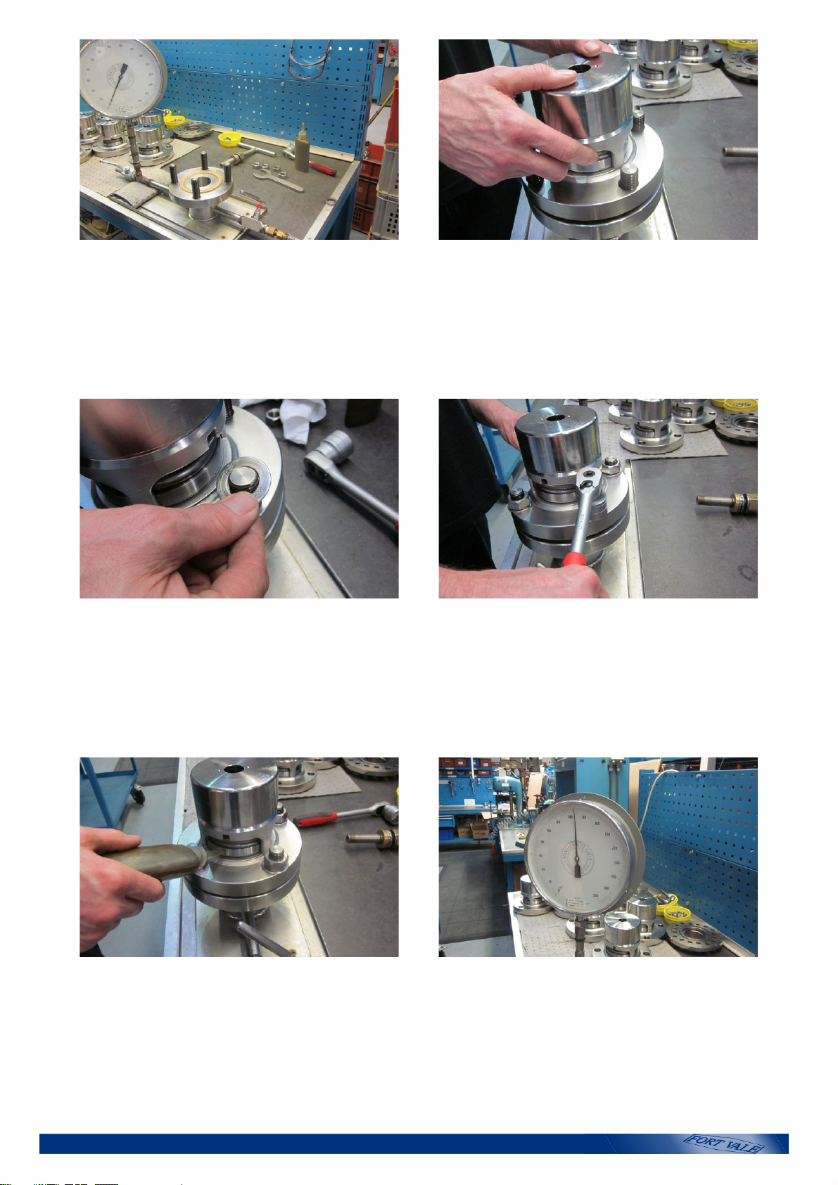
Step 50. Pressure testing should only be carried
out by a "qualified person". (See Maintenance
Safety Advice) A pressure test rig may be
purchased from Fort ale.
Step 51. Locate the valve body onto the 4x studs.
Step 52. Locate 4x washers. Step 53. Locate 4x nuts. Tighten the nuts in a
diametrically opposite sequence.
Step 54. Apply soapy water around the valve
where the pressure plate contacts the body.
Step 55. Apply pressure and look for bubbles
forming around the pressure plate. Note the
pressure at which this occurs. This indicates the
current set pressure of the valve. Exhaust the
pressure. To fine-adjust the valve to the required
set pressure, do the following:
MM050_REV01© Fort Vale Engineering Ltd. 2018 Page 14

Super Maxi Relief Valve - AAR Specification
Step 56a. To adjust the pressure to the required
setting, use pressure adjustment tool FIX/
A/0015/23. The tool has a 5/16" UNF female
thread which is designed to engage onto the 5/16"
stud on the pressure plate.
Step 56b. Locate the tool through the hole in the
top cap. Engage the 5/16" female thread of the
tool with the 5/16" stud in the pressure plate and
screw it until it is fully engaged. WARNING:
Ensure that the pressure is exhausted and the
pressure supply is OFF before adjusting the valve.
Step 57. When the tool is fully engaged, hold the
tee bar and use a 38mm (1½") A/F spanner to
tighten the brass jacking nut. This action will lift the
pressure plate off the sealing face, allowing the
valve cap to rotate.
Step 58. PRESSURE TOO LOW: If the valve test
pressure result was lower than the target set
pressure, rotate the tool/cap assembly approx. ½
turn clockwise. Loosen the jacking nut to re-seat
the pressure plate. Unscrew and remove the
adjustment tool. Repeat the pressure test (Step 54
& Step 55).
Step 5 . PRESSURE TOO HIGH: If the valve test
pressure result was higher than the target set
pressure, rotate the tool/cap assembly approx. ½
turn counter-clockwise. Loosen the jacking nut to
re-seat the pressure plate. Unscrew and remove
the adjustment tool. Repeat the pressure test
(Step 54 & Step 55).
Step 60. If necessary, repeat the adjustment and
pressure test until the target set pressure is
achieved. When the set pressure is correct,
reduce the test rig pressure by 10%. Apply soapy
water and test at the reduced pressure. Ensure
that no bubbles appear. This confirms that the
valve has re-sealed.
MM050_REV01© Fort Vale Engineering Ltd. 2018 Page 15

Super Maxi Relief Valve - AAR Specification
Step 61. When the valve is satisfactory, replace
the stainless steel plug. WARNING: Ensure that
the pressure is exhausted and the pressure supply
is OFF before removing the valve from the rig.
Step 62. When the pressure has been exhausted
from the test rig, remove the 4x nuts and washers
and remove the valve from the test rig.
Step 63. Refitting the anti-tamper screw: Use the
existing hole in the cap and drill a 4mm (No. 22)
hole to a depth of 5mm (0.2").
Step 64. Use a 3/16"BSW tap and tap the hole to
a depth of 4.6mm (0.18").
Step 65. Clean the hole using compressed air.
Caution: Wear appropriate eye PPE.
Step 66. Locate a 3/16"BSW x 3/16" long
sockethead screw. Use a 3/32" hex key to turn the
screw until it is recessed.
MM050_REV01© Fort Vale Engineering Ltd. 2018 Page 16
This manual suits for next models
4
Table of contents
Other Fort Vale Control Unit manuals


