Fortec Star COMe-bSC6 User manual

The information contained in this document has been carefully researched and is, to the best
of our knowledge, accurate. However, we assume no liability for any product failures or
damages, immediate or consequential, resulting from the use of the information provided
herein. Our products are not intended for use in systems in which failures of product could
result in personal injury. All trademarks mentioned herein are property of their respective
owners. All specifications are subject to change without notice.
Manual
COMe-bSC6
Kontron
Our company network supports you worldwide with offices in Germany, Austria,
Switzerland, Great Britain and the USA. For more information please contact:
FORTEC Elektronik AG
Hauptniederlassung
Lechwiesenstr. 9
86899 Landsberg am Lech
Telefon: +49 (0) 8191 91172-0
Telefax: +49 (0) 8191 21770
E-Mail: [email protected]
Internet: www.fortecag.de
FORTEC Elektronik AG
Büro West
Hohenstaufenring 55
50674 Köln
Telefon: +49 (0) 221 272 273-0
Telefax: +49 (0) 221 272 273-10
E-Mail: [email protected]
Internet: www.fortecag.de
FORTEC Elektronik AG
Büro Wien
Nuschinggasse 12
A-1230 Wien
Telefon: +43 1 8673492-0
Telefax: +43 1 8673492-26
E-Mail: [email protected]
Internet: www.fortec.at
ALTRAC AG
(Tochter der FORTEC):
Bahnhofstraße 3
CH-5436 Würenlos
Telefon: +41 (0) 44 7446111
Telefax: +41 (0) 44 7446161
E-Mail: [email protected]
Internet: www.altrac.ch

COMe-bSC6
Document Revision 150
www.kontron.com


» Table of Contents «
1User Information..................................................................................6
1.1 About This Document.................................................................................................................... 6
1. Copyright Notice.......................................................................................................................... 6
1.3 Trademarks................................................................................................................................. 6
1.4 Standards................................................................................................................................... 6
1.5 Warranty.................................................................................................................................... 7
1.6 Technical Support......................................................................................................................... 7
Introduction........................................................................................8
.1 Product Description...................................................................................................................... 8
. Naming clarification..................................................................................................................... 8
.3 Understanding COM Express® Functionality.......................................................................................8
.4 COM Express® Documentation.........................................................................................................9
.5 COM Express® Benefits.................................................................................................................. 9
3Product Specification..........................................................................10
3.1 Module definition....................................................................................................................... 10
3. Functional Specification............................................................................................................... 11
3.3 Block Diagram............................................................................................................................ 17
3.4 Variant Matrix............................................................................................................................ 17
3.5 Accessories............................................................................................................................... 18
3.6 Electrical Specification................................................................................................................ 19
3.6.1 Supply Voltage........................................................................................................................... 19
3.6. Power Supply Rise Time................................................................................................................ 19
3.6.3 Supply Voltage Ripple..................................................................................................................19
3.6.4 Power Consumption..................................................................................................................... 19
3.6.5 ATX Mode.................................................................................................................................. 0
3.6.6 Single Supply Mode..................................................................................................................... 0
3.7 Power Control............................................................................................................................ 1
3.8 Environmental Specification.........................................................................................................
3.8.1 Temperature Specification............................................................................................................
3.8. Humidity...................................................................................................................................
3.9 Standards and Certifications......................................................................................................... 3
3.10 MTBF........................................................................................................................................ 5
3.11 Mechanical Specification.............................................................................................................. 6
3.1 Module Dimensions..................................................................................................................... 7
3.13 Thermal Management, Heatspreader and Cooling Solutions................................................................. 8
3.14 Onboard Fan Connector................................................................................................................ 9
4Features and Interfaces.......................................................................30
4.1 S5 Eco Mode.............................................................................................................................. 30
4. LPC.......................................................................................................................................... 31
www.kontron.com

COMe-bSC6 /
4.3 Serial Peripheral Interface (SPI)....................................................................................................3
4.4 SPI boot.................................................................................................................................... 3
4.5 M.A.R.S.................................................................................................................................... 34
4.6 UART........................................................................................................................................ 35
4.7 Fast I C.................................................................................................................................... 36
4.8 GPIO - General Purpose Input and Output.........................................................................................37
4.9 Dual Staged Watchdog Timer.........................................................................................................38
4.10 Speedstep Technology................................................................................................................. 39
4.11 C-States.................................................................................................................................... 40
4.1 Hyper Threading......................................................................................................................... 41
4.13 VID-x....................................................................................................................................... 4
4.14 Intel® Turbo Boost Technology and AVX...........................................................................................43
4.15 Display Configuration.................................................................................................................. 44
4.16 Hybrid Graphics / Multi-monitor....................................................................................................48
4.17 Intel® vPro™ technology.............................................................................................................. 49
4.18 ACPI Suspend Modes and Resume Events..........................................................................................50
4.19 USB......................................................................................................................................... 51
5System Resources...............................................................................5
5.1 Interrupt Request (IRQ) Lines........................................................................................................ 5
5. Memory Area............................................................................................................................. 53
5.3 I/O Address Map......................................................................................................................... 53
5.4 Peripheral Component Interconnect (PCI) Devices.............................................................................54
5.5 I C Bus..................................................................................................................................... 54
5.6 JILI I C Bus............................................................................................................................... 54
5.7 SDVO I C Bus............................................................................................................................. 54
5.8 System Management (SM) Bus.......................................................................................................55
6Connectors........................................................................................56
6.1 Connector Location..................................................................................................................... 56
7Pinout List.........................................................................................57
7.1 General Signal Description............................................................................................................ 57
7. Connector X1A Row A................................................................................................................... 58
7.3 Connector X1A Row B................................................................................................................... 60
7.4 Connector X1B Row C................................................................................................................... 6
7.5 Connector X1B Row D................................................................................................................... 64
8BIOS Operation...................................................................................66
8.1 Determining the BIOS Version.......................................................................................................66
8. BIOS Update.............................................................................................................................. 66
8.3 Setup Guide............................................................................................................................... 68
8.4 POST Codes................................................................................................................................ 68
8.4.1 Start AMI® Aptio Setup Utility....................................................................................................... 68
4

COMe-bSC6 /
8.5 BIOS Setup................................................................................................................................ 70
8.5.1 Main........................................................................................................................................ 70
8.5. Advanced.................................................................................................................................. 7
8.5.3 Chipset..................................................................................................................................... 96
8.5.4 Boot....................................................................................................................................... 11
8.5.5 Security.................................................................................................................................. 114
8.5.6 Save & Exit............................................................................................................................... 116
5

COMe-bSC6 / User Information
1 User Information
1.1 About This Document
This document provides information about products from Kontron Europe GmbH and/or its subsidiaries. No warranty of
suitability, purpose, or fitness is implied. While every attempt has been made to ensure that the information in this
document is accurate, the information contained within is supplied “as-is” and is subject to change without notice.
For the circuits, descriptions and tables indicated, Kontron assumes no responsibility as far as patents or other rights of
third parties are concerned.
1.2 Copyright Notice
Copyright © 003- 014 Kontron Europe GmbH
All rights reserved. No part of this document may be reproduced, transmitted, transcribed, stored in a retrieval system, or
translated into any language or computer language, in any form or by any means (electronic, mechanical, photocopying,
recording, or otherwise), without the express written permission of Kontron Europe GmbH.
DIMM-PC®, PISA®, ETX®, ETXexpress®, microETXexpress®, X-board®, DIMM-IO® and DIMM-BUS® are trademarks or
registered trademarks of Kontron Europe GmbH. Kontron is trademark or registered trademark of Kontron AG.
1.3 Trademarks
The following lists the trademarks of components used in this board.
» IBM, XT, AT, PS/ and Personal System/ are trademarks of International Business Machines Corp.
» Microsoft is a registered trademark of Microsoft Corp.
» Intel is a registered trademark of Intel Corp.
» All other products and trademarks mentioned in this manual are trademarks of their respective owners.
1.4 Standards
Kontron Europe GmbH is certified to ISO 9000 standards.
6

COMe-bSC6 / User Information
1.5 arranty
For this Kontron Europe GmbH product warranty for defects in material and workmanship exists as long as the warranty
period, beginning with the date of shipment, lasts. During the warranty period, Kontron Europe GmbH will decide on its
discretion if defective products are to be repaired or replaced.
Within the warranty period, the repair of products is free of charge as long as warranty conditions are observed.
Warranty does not apply for defects arising/resulting from improper or inadequate maintenance or handling by the buyer,
unauthorized modification or misuse, as well as the operation outside of the product´s environmental specifications and
improper installation and maintenance.
Kontron Europe GmbH will not be responsible for any defects or damages to other products not supplied by Kontron
Europe GmbH that are caused by a faulty Kontron Europe GmbH product.
1.6 Technical Support
Technicians and engineers from Kontron Europe GmbH and/or its subsidiaries are available for technical support. We are
committed to make our product easy to use and will help you use our products in your systems.
Please consult our Website at http://www.kontron.com/support for the latest product documentation, utilities, drivers
and support contacts. Consult our customer section http://emdcustomersection.kontron.com for the latest BIOS
downloads, Product Change Notifications, Board Support Packages, DemoImages, 3D drawings and additional tools and
software. In any case you can always contact your board supplier for technical support.
7

COMe-bSC6 / Introduction
2 Introduction
2.1 Product Description
In 011, Intel® introduced its first quad core CPU suitable for the COM Express® platform. With the quad-core CPU Core™
i7- 715QE and the dual-core CPUs Core™ i3/i5/i7, COM Express® reaches ground-breaking performance values: both for
CPU and GPU rankings. With various CPUs COMe-bSC# serves your individual performance needs, starting with a 1.1 GHz
version Celeron® 847E.
Kontron's COMe-bSC# is available as COM Express® basic form factor (1 5x95mm) for Pin-out Type (COMe-bSC ) and
Pin-out Type 6 (COMe-bSC6).
2.2 Naming clarification
COM Express® defines a Computer-On-Module, or COM, with all components necessary for a bootable host computer,
packaged as a super component.
» COMe-bXX# modules are Kontron's COM Express® modules in basic form factor (1 5mm x 95mm)
» COMe-cXX# modules are Kontron's COM Express® modules in compact form factor (95mm x 95mm)
» COMe-mXX# modules are Kontron's COM Express® modules in mini form factor (55mm x 84mm)
The product names for Kontron COM Express® Computer-on-Modules consist of a short form of the industry standard
(COMe-), the form factor (b=basic, c=compact, m=mini), the capital letters for the CPU and Chipset Codenames ( ) and
the pin-out type (#) followed by the CPU Name.
2.3 Understanding COM Express® Functionality
All Kontron COM Express® basic and compact modules contain two 0pin connectors; each of it has two rows called Row
A & B on primary connector and Row C & D on secondary connector. COM Express® Computer-on-modules feature the
following maximum amount of interfaces according to the PICMG module Pin-out type:
Feature Pin-Out Type 1 Pin-Out Type 10 Pin-Out Type 2 Pin-Out Type 6
HD Audio 1x 1x 1x 1x
Gbit Ethernet 1x 1x 1x 1x
Serial ATA 4x 4x 4x 4x
Parallel ATA - - 1x -
PCI - - 1x -
PCI Express x1 6x 6x 6x 8x
PCI Express x16 (PEG) - - 1x 1x
USB Client 1x 1x - -
USB 2.0 8x 8x 8x 8x
USB 3.0 - x - 4x
VGA 1x - 1x 1x
LVDS Dual Channel Single Channel Dual Channel Dual Channel
DP++ (SDVO/DP/HDMI/DVI) 1x optional 1x 3x shared with PEG 3x
LPC 1x 1x 1x 1x
External SMB 1x 1x 1x 1x
External I2C 1x 1x 1x 1x
GPIO 8x 8x 8x 8x
SDIO shared w/GPIO 1x optional 1x optional - 1x optional
UART (2-wire COM) - x - x
FAN PWM out - 1x - 1x
8

COMe-bSC6 / Introduction
2.4 COM Express® Documentation
This product manual serves as one of three principal references for a COM Express® design. It documents the
specifications and features of COMe-bSC6. Additional references are available at your Kontron Support or at PICMG®:
» The COM Express® Specification defines the COM Express® module form factor, pin-out, and signals. This document
is available at the PICMG® website by filling out the order form.
» The COM Express® Design Guide by PICMG® serves as a general guide for baseboard design, with a focus on
maximum flexibility to accommodate a wide range of COM Express® modules.
Some of the information contained within this product manual applies only to certain
product revisions (CE: xxx). If certain information applies to specific product revisions (CE:
xxx) it will be stated. Please check the product revision of your module to see if this
information is applicable.
2.5 COM Express® Benefits
COM Express® modules are very compact, highly integrated computers. All Kontron COM Express® modules feature a
standardized form factor and a standardized connector layout which carry a specified set of signals. Each COM is based on
the COM Express® specification. This standardization allows designers to create a single-system baseboard that can
accept present and future COM Express® modules.
The baseboard designer can optimize exactly how each of these functions implements physically. Designers can place
connectors precisely where needed for the application on a baseboard designed to optimally fit a system’s packaging.
A single baseboard design can use a range of COM Express® modules with different sizes and pin-outs. This flexibility can
differentiate products at various price/performance points, or when designing future proof systems that have a built-in
upgrade path. The modularity of a COM Express® solution also ensures against obsolescence when computer technology
evolves. A properly designed COM Express® baseboard can work with several successive generations of COM Express®
modules.
A COM Express® baseboard design has many advantages of a customized computer-board design and, additionally,
delivers better obsolescence protection, heavily reduced engineering effort, and faster time to market.
9
COMe-bSC6 / Product Specification
3 Product Specification
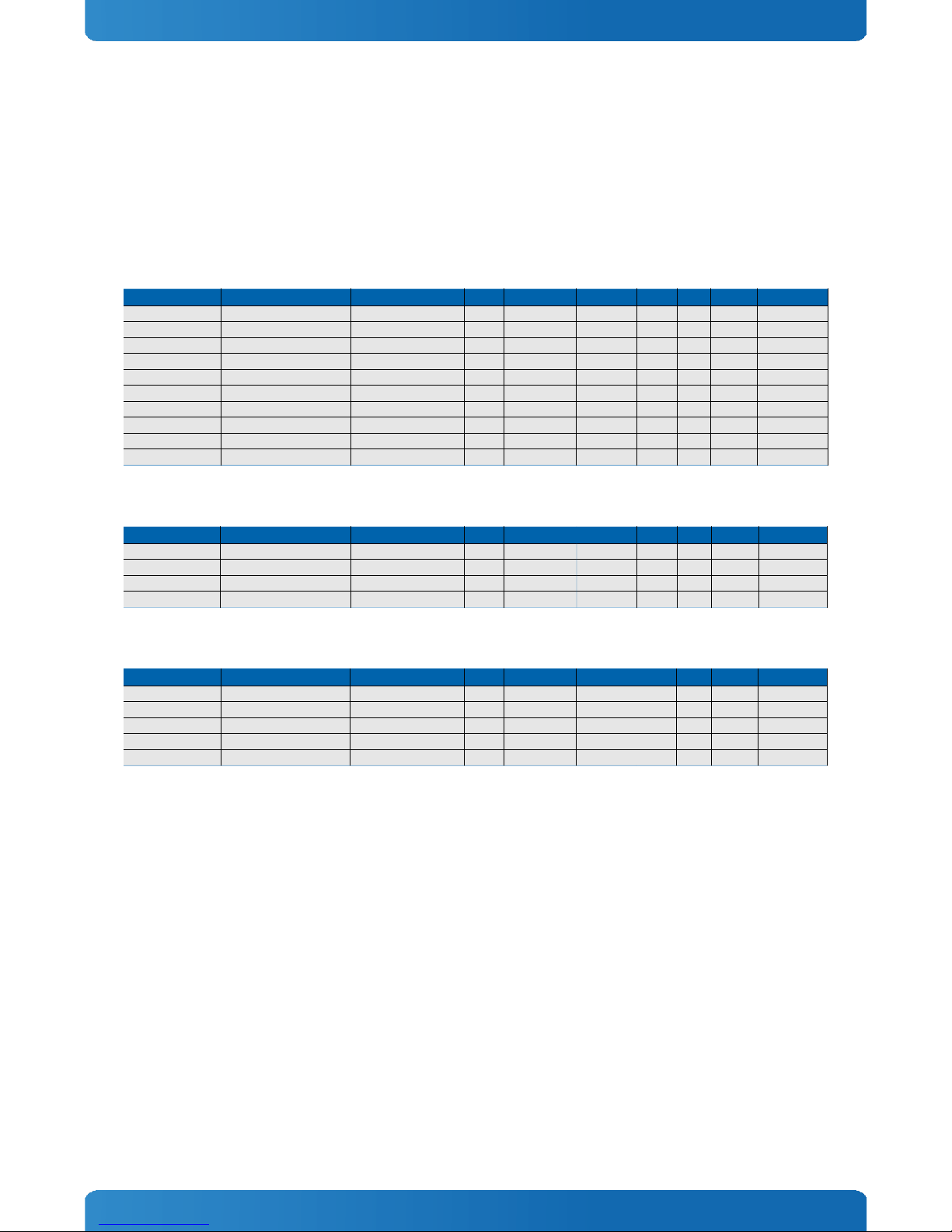
3.1 Module definition
The COM Express® basic sized Computer-on-Module COMe-bSC6 (CHR6) follows pin-out Type 6 and is compatible to PICMG
specification COM.0 Rev .0. The COMe-bSC6 based on latest Huron River platform is available in different variants to
cover the demand of different performance, price and power:
Commercial grade ECC modules (0°C to 60°C operating)
Product Number Product Name Processor PCH Memory Graphics PEG TPM USB 2.0 USB 3.0
38014-0000- 1-4 COMe-bSC6 i7- 715QE ECC Intel® Core™ i7- 715QE QM67 x DDR3-ECC HD3000 YES YES 8x x
38014-0000- - COMe-bSC6 i7- 655LE ECC Intel® Core™ i7- 655LE QM67 x DDR3-ECC HD3000 YES YES 8x x
38014-0000-15- COMe-bSC6 i7- 610UE ECC Intel® Core™ i7- 610UE QM67 x DDR3-ECC HD3000 YES YES 8x x
38014-0000- 5- COMe-bSC6 i5- 515E ECC Intel® Core™ i5- 515E QM67 x DDR3-ECC HD3000 YES YES 8x x
38014-0000- 1- COMe-bSC6 i3- 310E ECC Intel® Core™ i3- 310E QM67 x DDR3-ECC HD3000 YES YES 8x x
38014-0000-13- COMe-bSC6 i3- 340UE ECC Intel® Core™ i3- 340UE QM67 x DDR3-ECC HD3000 YES YES 8x x
38014-0000-16-1 COMe-bSC6 B810E ECC Intel® Celeron® B810E HM65 x DDR3-ECC HD YES YES 6x optional
38014-0000-11-1 COMe-bSC6 847E ECC Intel® Celeron® 847E HM65 x DDR3-ECC HD YES YES 6x optional
38014-0000-14-0 COMe-bSC6 8 7E ECC Intel® Celeron® 8 7E HM65 x DDR3-ECC HD YES YES 6x optional
38014-0000-10-0 COMe-bSC6 807UE ECC Intel® Celeron® 807UE HM65 1x DDR3-ECC HD - YES 6x optional
Commercial grade non-ECC modules (0°C to 60°C operating)
Product Number Product Name Processor PCH Memory Graphics PEG TPM USB 2.0 USB 3.0
380 3-0000-16-1 COMe-bSC6 B810E Intel® Celeron® B810E HM65 x DDR3 HD YES YES 8x -
380 3-0000-11-1 COMe-bSC6 847E Intel® Celeron® 847E HM65 x DDR3 HD YES YES 8x -
380 3-0000-14-0 COMe-bSC6 8 7E Intel® Celeron® 8 7E HM65 x DDR3 HD YES YES 8x -
380 3-0000-10-0 COMe-bSC6 807UE Intel® Celeron® 807UE HM65 1x DDR3 HD - YES 8x -
Extended temperature ECC modules (E1, -25°C to 75°C operating)
Product Number Product Name Processor PCH Memory Graphics PEG TPM USB 2.0 USB 3.0
38014-0000- - EXT COMe-bSC6 i7- 655LE ECC E1 Intel® Core™ i7- 655LE QM67 x DDR3-ECC HD3000 YES - 8x x
38014-0000-15- EXT COMe-bSC6 i7- 610UE ECC E1 Intel® Core™ i7- 610UE QM67 x DDR3-ECC HD3000 YES - 8x x
38014-0000-11-1EXT COMe-bSC6 847E ECC E1 Intel® Celeron® 847E HM65 x DDR3-ECC HD YES - 6x optional
38014-0000-14-0EXT COMe-bSC6 8 7E ECC E1 Intel® Celeron® 8 7E HM65 x DDR3-ECC HD YES - 6x optional
38014-0000-10-0EXT COMe-bSC6 807UE ECC E1 Intel® Celeron® 807UE HM65 1x DDR3-ECC HD - - 6x optional
10

COMe-bSC6 / Product Specification
3.2 Functional Specification
Processor
The 3 nm Intel® nd Gen Core™ i7/i5/i3/Celeron® embedded (Sandy Bridge) CPU family with 31x 4mm package size
(FCBGA10 3 socket) supports:
» Intel® Turbo Boost Technology .0
» Intel® 64
» Intel® Virtualization Technology (VT-x)
» Intel® Virtualization Technology for Directed I/O (VT-d)
» AES New Instructions (AES-NI)
» Intel® Anti-Theft Technology
» Intel® Hyper-Threading Technology
» Enhanced Intel SpeedStep® Technology
» Idle States (C-States)
» Intel® Smart Cache
» Thermal Monitoring Technologies
» Intel® Fast Memory Access
» Intel® Flex Memory Access
» Integrated Intel® HD Graphics with Dynamic Frequency
Optional available (with customized BIOS):
» Intel® vPRO™ Technology including:
» Intel® Active Management Technology (AMT)
» Intel® Trusted Execution Technology (TXT)
The integrated Intel® HD3000 Graphics supports:
» GraphicsTechnology GT with 1 Execution Units
» Intel® Quick Sync Video
» Intel® InTru™ 3D Technology
» Intel® Wireless Display
» Intel® Flexible Display Interface (Intel® FDI)
» Intel® Clear Video HD Technology
» Dual Display
The integrated Intel® HD Graphics supports:
» GraphicsTechnology GT1 with 6 Execution Units
» Dual Display
11
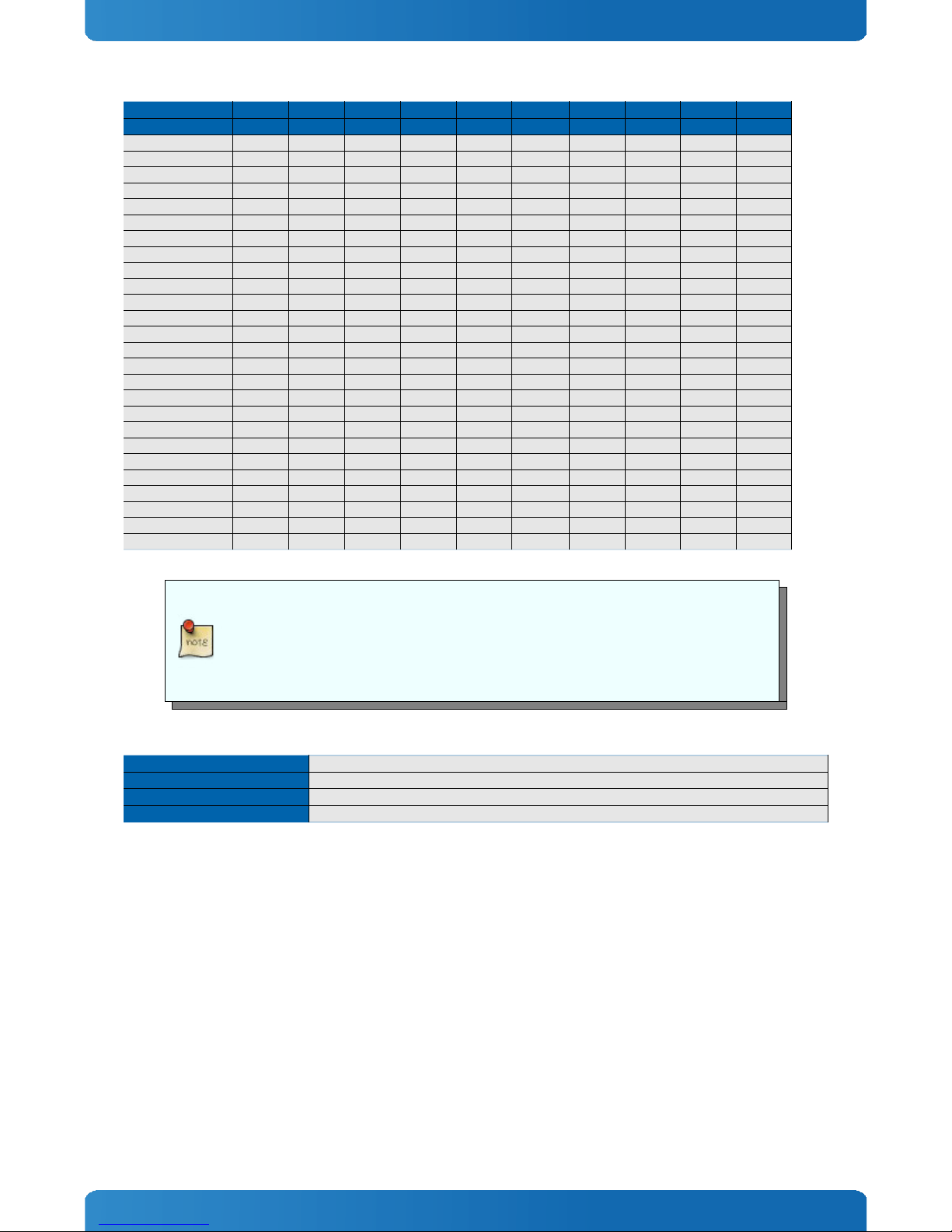
COMe-bSC6 / Product Specification
Intel® Core™ Core™ Core™ Core™ Core™ Core™ Celeron® Celeron® Celeron® Celeron®
- i7-2715QE i7-2655LE i7-2610UE i5-2515E i3-2310E i3-2340UE B810E 847E 827E 807UE
# of Cores 4 1 1
# of Threads 8 4 4 4 4 4 1 1
Clock Speed 100MHz 00MHz 1500MHz 500MHz 100MHz 1300MHz 1600MHz 1100MHz 1400MHz 1000MHz
Max Turbo Frequency 3000MHz 900MHz 400MHz 3100MHz - - - - - -
TDP 45W 5W 17W 35W 35W 17W 35W 17W 17W 10W
C-States C0-C7 C0-C7 C0-C7 C0-C7 C0-C7 C0-C7 C0-C3 C0-C3 C0-C3 C0-C3
Smart Cache 6MB 4MB 4MB 3MB 3MB 3MB MB MB 1.5MB 1MB
Bus/Core Ratio 1 - 1 8- 8-15 8- 5 8- 1 8-13 8-16 8-11 8-14 8-10
Min Memory Type DDR3-1066 DDR3-1066 DDR3-1066 DDR3-1066 DDR3-1066 DDR3-1066 DDR3-1066 DDR3-1066 DDR3-1066 DDR3-1066
Max Memory Type DDR3-1600 DDR3-1333 DDR3-1333 DDR3-1333 DDR3-1333 DDR3-1333 DDR3-1333 DDR3-1333 DDR3-1333 DDR3-1333
Max Memory Size 16GB 16GB 16GB 16GB 16GB 16GB 16GB 16GB 16GB 4GB
# of Memory Channels 1
Graphics Model HD3000 HD3000 HD3000 HD3000 HD3000 HD3000 HD HD HD HD
GFX Base Frequency 650MHz 650MHz 350MHz 650MHz 650MHz 350MHz 650MHz 350MHz 350MHz 350MHz
GFX Max Dynamic Frequ. 1 00MHz 1000MHz 850MHz 1100MHz 1050MHz 800MHz 1000MHz 800MHz 800MHz 800MHz
Quick Sync Video Yes Yes Yes Yes Yes Yes - - - -
InTru™ 3D Yes Yes Yes Yes Yes Yes - - - -
Wireless Display Yes Yes Yes Yes Yes Yes - - - -
Clear Video HD Yes Yes Yes Yes Yes Yes - - - -
PCI Express Graphics Yes Yes Yes Yes Yes Yes Yes Yes Yes -
vPRO™ (optional) Yes Yes Yes Yes - - - - - -
TXT (optional) Yes Yes Yes Yes - - - - - -
AES-NI Yes Yes Yes Yes - - - - - -
VT-x Yes Yes Yes Yes Yes Yes Yes Yes Yes Yes
VT-d Yes Yes Yes Yes - - - - - -
Anti-Theft Yes Yes Yes Yes Yes Yes - - - -
The Bus/Core Ratio shows the possible CPU Performance settings (CPU Ratio) from the max
Efficiency Ratio (LFM = Lowest Frequency Mode) to the maximum non-turbo Ratio (HFM =
Highest Frequency Mode). If enabled in Setup, CPU Clock is fixed to Ratio*100MHz. This
feature is not supported with updated EFI Core available with BIOS CHR6R111 or newer.
Memory
Sockets x DDR3 SO-DIMM
Memory Type DDR3-1066/1333 ECC/nonECC
Maximum Size x8GB
Technology Dual Channel
Chipset
The Intel® 6-Series Platform Controller Hub Cougar Point supports:
» PCI Express Revision .0
» PCI Express Configurations x1, x , x4
» Intel® Virtualization Technology for Directed I/O (VT-d)
» Intel® Trusted Execution Technology (TXT)
» Intel® vPro Technology
» Intel® Active Management Technology 7.0
» Intel® Anti-Theft Technology
» Intel® Rapid Storage Technology
12

COMe-bSC6 / Product Specification
PCH comparison
Feature QM67 HM65
TDP 3.9W 3.9W
VT-d YES NO
TXT YES NO
vPRO YES NO
AMT YES NO
Rapid Storage YES NO
SATA RAID YES NO
The Intel® vPro Technology including Trusted Execution Technology (TXT) and Active
Management Technology (AMT) is not supported by default on COMe-bSC6. Please contact
your local sales or support for custom BIOS variants supporting vPro. A test version is
available on EMD Customer Section.
Graphics Core
The integrated Intel® HD/HD3000 (Gen6) supports:
Graphics Core Render Clock GT1 /GT , Base clock: 350/650 MHz, GT Turbo: up to 1 00 MHz
Execution Units / Pixel Pipelines GT : 1 EU / GT1: 6EU
Max Graphics Memory 17 0MB
GF Memory Bandwidth (GB/s) 1.3
GF Memory Technology DVMT 5.0
API (Direct /OpenGL) 10.1 / 3.0
Shader Model 4.0
Hardware accelerated Video MPEG , VC-1, AVC, Blu-ray (+3D)
Independent/Simultaneous Displays
Display Port DP 1.1a / eDP
HDCP support HDCP 1.4
Monitor output
CRT max Resolution 048x1536
TV out: -
LVDS
LVDS Bits/Pixel 1x18/ 4, x18/ 4
LVDS Bits/Pixel with dithering -
LVDS max Resolution: 19 0x1 00
PWM Backlight Control: YES
Supported Panel Data: JILI /JILI3/EDID/DID
Display Interfaces
Discrete Graphics 1x PEG .0 (not on Cel. 807UE)
Digital Display Interface DDI1 DP++/SDVOB
Digital Display Interface DDI2 DP++
Digital Display Interface DDI3 DP++/eDP
Maximum Resolution on DDI 560x1600
13

COMe-bSC6 / Product Specification
PEG Configuration
The x16 PCI Express Graphics Port (PEG) is compatible to standard PCI Express devices like Ethernet or RAID controllers.
The COMe-bSC6 supports following PEG Port configuration when used as PCI Express Interface:
» 1×16
» 1×8
» 1×4
» 1×
» 1×1
The internal PCI Express controller can be re-configured to support up to 3 PCIe ports. The following port configurations
are available via hardware strap options (customized article):
» ×8 (lanes #0-7 + #8-15)
» 1×8 + ×4 (lanes #0-7 + #8-11 + #1 -15)
Storage
onboard SSD -
SD Card support -
IDE Interface -
Serial-ATA x SATA 6Gb/s, x SATA 3Gb/s
SATA AHCI NCQ, HotPlug, Staggered Spinup, eSATA, PortMultiplier
SATA RAID 0, 1, 5, 10, MATRIX (QM67 only)
If SATA AHCI or RAID is disabled in setup, the SATA Interface only supports 3Gb/s transfer
rate and Staggered Spin-Up. To configure a RAID enable RAID support in BIOS Chipset/SATA
settings, connect at least two hard drives and enter the RAID Option ROM by pressing
'CTRL'+'I'
Connectivity
USB 2.0 up to 8x USB .0
USB 3.0 up to x USB 3.0
USB Client -
PCI -
PCI External Masters -
PCI Express 6x PCIe x1 Gen
Max PCI Express 7x PCIe without USB 3.0
PCI Express x2/x4 configuration YES (Softstrap option)
Ethernet 10/100/1000 Mbit
Ethernet controller Intel® 8 579LM (Lewisville)
- Due to internal chipset configuration the Cougar Point only supports up to 4 USB Hubs
- On Type6 modules with USB3.0 legacy support is disabled in POST for the USB 3.0 Ports
0/1
14

COMe-bSC6 / Product Specification
PCI Express Configuration
The COMe-bSC6 only supports x1 PCIexpress lane configuration by default. Following x /x4 configurations are available
via Management Engine Softstrap Options with a customized BIOS version.
PCIe Port #0 Port #1 Port #2 Port #3 Port #4 Port #5* Port #6* Port #7*
Configuration0 x1 x1 x1 x1 x1 - - -
Configuration1 x x1 x1 x1 x1 x1 x1
Configuration x x x1 x1 x1 x1
Configuration3 x x x x1 x1
Configuration4 x x x x
Configuration5 x4 x1 x1 x1 x1
Configuration6 x4 x x1 x1
Configuration7 x4 x x
Configuration8 x4 x4
- *PCIe Port #6 is only available on variants without Renesas USB 3.0 Controller and Port #7
is available without Ethernet Controller
- Configuration0 (default) and Configuration5 (modified FlashDescriptor) are provided in
BIOS download package available on EMD Customer Section
Ethernet
The Intel® 8 579LM (Lewisville) ethernet supports:
» Jumbo Frames
» MACsec IEEE 80 .1 AE
» Time Sync Protocol Indicator
» WOL (Wake On LAN)
» PXE (Preboot eXecution Environment)
Misc Interfaces and Features
Supported BIOS Size/Type 8MB SPI
Audio HD Audio + DisplayPort dual stream
Onboard Hardware Monitor Analog Devices ADT7490
Trusted Platform Module Infineon TPM 1. SLB9635TT
Miscellaneous x UART / PWM FAN
Kontron Features
External I2C Bus Fast I C, MultiMaster capable
M.A.R.S. support YES
Embedded API KEAPI1 / KEAPI
Custom BIOS Settings / Flash Backup YES
Watchdog support Dual Staged
Additional features
» All solid capacitors (POSCAP). No tantalum capacitors used.
» Optimized RTC Battery monitoring to secure highest longevity
» Real fast I C with transfer rates up to 40kB/s.
» Discharge logic on all onboard voltages for highest reliability
15

COMe-bSC6 / Product Specification
Power Features
Singly Supply Support YES
Supply Voltage 8.5V - 18V ( 0V@nonECC)
ACPI ACPI 4.0
S-States S0, S3, S4, S5
S5 Eco Mode YES
Misc Power Management DPST 6.0
Power Consumption and Performance
Full Load Power Consumption 10 - 73W
Kontron Performance Index 11571 - 63719
Kontron Performance/Watt 878 - 161
*Measured Values. Please note the maximum Power Consumption with activated Turbo Mode in chapter Turbo .0
Detailed Power Consumption measurements in all states and benchmarks for CPU, Graphics
and Memory performance are available in Application Note KEMAP054 at EMD Customer
Section.
16

COMe-bSC6 / Product Specification
3.3 Block Diagram
3.4 Variant Matrix
The COMe-bSC6 is available with different PCB and featureset. The following table shows major differences of available
standard modules:
Product Name COMe-bSC6 ECC COMe-bSC6 ECC E1 COMe-bSC6
Part.No. 38014-xxxx-xx-x 38014-xxxx-xx-xEXT 380 3-xxxx-xx-x
Temperature Grade commercial extended commercial
PCB/Project Code CHR6 CHR6 CCR6
BIOS/UEFI CHR6Rxxx CHR6Rxxx CHR6Rxxx
HW Revision CE 1.x.x CE 1.x.x CE 1.x.x
DDR3 Memory ECC ECC non-ECC
USB #6/#7 Support with QM67 PCH only with QM67 PCH only Yes
USB 3.0 Support Yes Yes No
eDP Support on DDI3 No No Yes
TPM Infineon FW 1.0 No Infineon FW 3.17
HWM ADT7490 ADT7490 NCT780 Y
17
FAN Control
PwrCtrl / Battery
DDR3-1333
DDR3-1333
X4 DMIFDI
PCIe #0 - #5
Intel® 2nd Generation Core
GMA HD3000
SATA #0/1 6Gb/s)
HDAudio
I2C
Connector CD
USB #2 - #7
PCIe #7GB LAN
CPLD
(Embedded
Controller)
JIDA
EEPROM
8 GPIO
FAN
Connector
SPI
SMB
DDR3 SODIMM
ECC or nonECC
DDR3 SODIMM
ECC or nonECC
CRT
LVDS
PEG
DDI1 SDVO/DP/HDMI/DVI)
DDI2 DP/HDMI/DVI)
DDI3 eDP/DP/HDMI/DVI)
SATA #2/3 3Gb/s)
PCIe #6
Ethernet
Intel® 82579
PCIe2USB 3.0
Renesas
USB 3.0 #0/#1)
Watchdog
H M
ADT7490 PECISMB
HWM
LPC
TPM
Infineon
SLB9635TT
Connector AB
BIOS
SPI Flash
Intel® 6-Series PCH
Intel® QM67
Intel® HM65
USB #0 - #1
2 x UART RX/TX)
Ethernet
MAC
PCIe #6
optional
DDIB
DDIC
DDID

COMe-bSC6 / Product Specification
3.5 Accessories
Product specific accessories
Product Number Heatspreader and Cooling Solutions Comment
38013-0000-99-0 HSP COMe-bSC/IP thread For CPUs up to 5W TDP and commercial temperature grade usage
38013-0000-99-1 HSP COMe-bSC/IP through For CPUs up to 5W TDP and commercial temperature grade usage
38013-0000-99- HSP COMe-bSC/IP heatpipe thread For all CPUs and temperature grades
38013-0000-99-3 HSP COMe-bSC/IP heatpipe through For all CPUs and temperature grades
38013-0000-99-0C05 HSK COMe-bSC/IP active setscrew thread For all CPUs and commercial temperature grade usage
38013-0000-99-1C05 HSK COMe-bSC/IP active setscrew through hole For all CPUs and commercial temperature grade usage
38013-0000-99-0C06 HSK COMe-bSC/IP passive setscrew thread For all CPUs and commercial temperature grade usage
38013-0000-99-1C06 HSK COMe-bSC/IP passive setscrew through hole For all CPUs and commercial temperature grade usage
General accessories
Part Number COMe pin-out Type 6 compatible accessories Project Code Comment
38114-0000-00-0 COM Express® Reference Carrier Type 6 ADAS mITX Carrier with 8mm COMe connector
38106-0000-00-0 COM Express® Eval Carrier Type 6 Topanga Canyon ATX Carrier with 5mm COMe connector
96007-0000-00-3 ADA-PCIe-DP APDP PCIe x16 to DP Adapter for Evaluation Carrier
96007-0000-00-7 ADA-Type6-DP3 DVO6 (sandwich) Adapter Card for 3x DisplayPort
96006-0000-00- COMe POST T6 NFCB POST Code / Debug Card
38019-0000-00-0 ADA-COMe-Height-dual EERC Height Adapter
38106-0000-00-S COMe Eval Starterkit T6 Topanga Canyon Starterkit with COMe Evaluation Carrier T6
38114-0000-00-S COMe Ref. Starterkit T6 ADAS Starterkit with COMe Reference Carrier T6
Part Number Mounting Comment
38017-0000-00-5 COMe Mount KIT 5mm 1set Mounting Kit for 1 module including screws for 5mm connectors
38017-0100-00-5 COMe Mount KIT 5mm 100sets Mounting Kit for 100 modules including screws for 5mm connectors
38017-0000-00-0 COMe Mount KIT 8mm 1set Mounting Kit for 1 module including screws for 8mm connectors
38017-0100-00-0 COMe Mount Kit 8mm 100sets Mounting Kit for 100 modules including screws for 8mm connectors
Part Number Cooling Solutions Comment
36099-0000-99-0 COMe Active Uni Cooler for CPUs up to 0W TDP, to be mounted on HSP
36099-0000-99-1 COMe Passive Uni Cooler for CPUs up to 10W TDP, to be mounted on HSP
Part Number Display Adapter Comment
9-5000-035 ADA-LVDS-DVI 18bit LVDS to DVI converter
9-5000-0353 ADA-LVDS-DVI 4bit LVDS to DVI converter
96006-0000-00-8 ADA-DP-LVDS DP to LVDS adapter
9608 -0000-00-0 KAB-ADAPT-DP-DVI DP to DVI adapter cable
96083-0000-00-0 KAB-ADAPT-DP-VGA DP to VGA adapter cable
96084-0000-00-0 KAB-ADAPT-DP-HDMI DP to HDMI adapter cable
Part Number Cables Comment
96079-0000-00-0 KAB-HSP 00mm Cable adapter to connect FAN to module (COMe basic/compact)
96079-0000-00- KAB-HSP 40mm Cable adapter to connect FAN to module (COMe basic/compact)
Part Number Miscellaneous Comment
180 9-0000-00-0 MARS Smart Battery Kit Starterkit Kontron Mobile Application platform for Rechargeable Systems
For COMe-bSC6 ECC (38014-xxxx-xx-x)
Part Number DDR3 ECC SODIMM, commercial temperature grade
97016-10 4-16-0 DDR3-1600 SODIMM 1GB ECC
97016- 048-16-0 DDR3-1600 SODIMM GB ECC
97016-4096-16-0 DDR3-1600 SODIMM 4GB ECC
97016-819 -16-0 DDR3-1600 SODIMM 8GB ECC
Part Number DDR3 ECC SODIMM, industrial temperature grade
97016-10 4-16- DDR3-1600 SODIMM 1GB ECC E
97016- 048-16- DDR3-1600 SODIMM GB ECC E
97016-4096-16- DDR3-1600 SODIMM 4GB ECC E
97016-819 -16- DDR3-1600 SODIMM 8GB ECC E
For COMe-bSC6 non-ECC (38023-xxxx-xx-x)
Part Number DDR3 SODIMM, commercial temperature grade
97015-10 4-16-0 DDR3-1600 SODIMM 1GB
97015- 048-16-0 DDR3-1600 SODIMM GB
97015-4096-16-0 DDR3-1600 SODIMM 4GB
97015-819 -16-0 DDR3-1600 SODIMM 8GB
Part Number DDR3 SODIMM, industrial temperature grade
97015-10 4-16- DDR3-1600 SODIMM 1GB E
97015- 048-16- DDR3-1600 SODIMM GB E
97015-4096-16- DDR3-1600 SODIMM 4GB E
97015-819 -16- DDR3-1600 SODIMM 8GB E
18

COMe-bSC6 / Product Specification
3.6 Electrical Specification
3.6.1 Supply Voltage
Following supply voltage is specified at the COM Express® connector:
VCC: 8.5V - 18V ( 0V@nonECC)
Standby: 5V DC +/- 5%
RTC: .5V - 3.47V
- 5V Standby voltage is not mandatory for operation.
- Extended Temperature (E1) variants are validated for 1 V supply only
3.6.2 Power Supply Rise Time
» The input voltages shall rise from ≤10% of nominal to within the regulation ranges within 0.1ms to 0ms.
» There must be a smooth and continuous ramp of each DC input voltage from 10% to 90% of its final set-point
following the ATX specification
3.6.3 Supply Voltage Ripple
» Maximum 100 mV peak to peak 0 – 0 MHz
3.6.4 Power Consumption
The maximum Power Consumption of the different COMe-bSC6 variants is 10 - 73W (100% CPU load on all cores; 90°C CPU
temperature). Further information with detailed measurements are available in Application Note KEMAP054 available on
EMD Customer Section. Information there is available after registration.
19
Table of contents
Popular Control Unit manuals by other brands


American Standard
American Standard SELECTRONIC 605XTMV1070 installation instructions

Oracle
Oracle Sun StorageTek SG-XPCIEFCGBEE8-Z installation guide

AMES
AMES 2000 CIV Series Installation, Service, Repair Kits, Maintenance

MG
MG R8-SST8 instruction manual

EPA
EPA SM-Ethernet user guide

Aumuller
Aumuller USKM Assembly and commissioning instructions


