Fortinet FortiGate-5144C User manual

FortiGate-5144C Chassis Guide
FortiGate-5000 Series

FORTINET DOCUMENT LIBRARY
https://docs.fortinet.com
FORTINET VIDEO GUIDE
https://video.fortinet.com
FORTINET BLOG
https://blog.fortinet.com
CUSTOMER SERVICE & SUPPORT
https://support.fortinet.com
FORTINET TRAINING & CERTIFICATION PROGRAM
https://www.fortinet.com/support-and-training/training.html
NSE INSTITUTE
https://training.fortinet.com
FORTIGUARD CENTER
https://fortiguard.com/
END USER LICENSE AGREEMENT
https://www.fortinet.com/doc/legal/EULA.pdf
FEEDBACK
Email: techdoc@fortinet.com
13 April, 2020
FortiGate-5144C 6.2.3 Chassis Guide
01-623-246510-20200413

TABLEOFCONTENTS
Change log 6
FortiGate-5144C Chassis 7
FortiGate-5144C front panel 7
FortiGate-5144C back panel 8
Chassis hardware information 9
Shipping components 10
Accessories 10
Supported Fortinet ATCA boards 10
Power requirements 12
Physical description of the FortiGate-5144C chassis 12
FortiGate-5144C shelf managers 13
Connecting to the Shelf manager and shelf manager Ethernet channels 14
Shelf manager Ethernet connections to chassis slots (and boards) 15
Changing the shelf manager switch configuration to prevent Ethernet loops 15
Radial IPMB bus topology 17
Using the shelf manager CLI 18
Shelf Manager fan and power control 18
Telco alarms 18
Air Filter 19
Cooling fans, cooling air flow, and minimum clearance 20
FortiGate-5144C hardware procedures 22
Mounting the FortiGate-5144C chassis 22
Air flow 23
Inserting FortiGate-5000 series boards and RTM modules 23
Installing FortiController or FortiSwitch boards 24
Power connection and configuration 25
FortiGate-5144C chassis power level requirements 25
Connecting the FortiGate-5144C chassis to DC power and ground 26
Crimping guidelines 27
Connecting FortiGate-5144C power feeds to DC power 28
Connecting the FortiGate-5144C chassis to ground 29
FortiGate-5053B power supply shelf and PSU-5000B power supplies 30
Power requirement guidelines 32
Connecting a FortiGate-5144C chassis to the FortiGate-5053B power supply shelf 32
Connecting the FortiGate-5053B power supply shelf to ground 34
Turning on FortiGate-5144C chassis power 35
Shelf Manager CLI 36
Connecting to the shelf manager CLI using the shelf manager console port 36
Connecting to the shelf manager CLI from an Ethernet network 37
Changing the shelf manager root account password 38
Resetting a lost shelf manager password 38
The shelf manager command line interface agent (CLIA) 39
Using CLIA interactive mode 39
FortiGate-5144C Chassis Guide 3
Fortinet Technologies Inc.

Fortinet Technologies Inc.
IPMB addresses, logical and physical slot numbers, and FRU ids 39
Change IP address of the primary Shelf Manager 41
Display the shelf manager firmware version 41
List all FRUs in the chassis 42
List all sensors on a FRU 42
List only sensors that are outside of established thresholds 42
Display sensor data for a FRU 42
Display the FRU information for a FRU 42
Change the speed for a fan tray 42
Display the contents of the system event log (sel) 42
Clear the system event log (sel) 42
Changing the shelf manager IP address and default gateway 43
Sensor types 44
CLI command Reference 44
activate/deactivate 44
alarm 45
board 46
clia 47
exit/quit 47
fans 47
fru 48
fruinfo 48
getlanconfig 49
getthreshold/threshold 50
help 53
minfanlevel 56
sel 56
sensor 57
sensordata 58
setthreshold 58
shmstatus 60
showunhealthy 60
switchover 61
terminate 61
user 61
version 63
Generating SNMP traps for shelf manager system events 64
Example SNMP configuration 64
Testing the configuration 68
SNMP trap details 68
Removing and inserting a fan tray 70
Setting up SNMP polling for the shelf manager 70
Using the shelf manager system event log (SEL) 71
Before you begin 71
Chassis design background 71
Alarm LEDs 72
Reading the SEL 72
FortiGate-5144C Chassis Guide 4

Fortinet Technologies Inc.
Clearing SEL logs 73
Example IPMC log output 74
Example FRU log output 75
Example sensor log output 76
Sample sections of SEL Output 88
Regulatory notices, cautions and warnings 89
Federal Communication Commission (FCC) – USA 89
Industry Canada Equipment Standard for Digital Equipment (ICES) – Canada 89
Voluntary Control Council for Interference (VCCI) – Japan 89
Bureau of Standards Metrology and Inspection (BSMI) – Taiwan 90
China 90
European Conformity (CE) - EU 90
Environmental specifications 90
Safety 91
FortiGate-5144C Chassis Guide 5

Change log Fortinet Technologies Inc.
Change log
Date Change description
April 13, 2020 New version.
FortiGate-5144C Chassis Guide 6

FortiGate-5144C Chassis
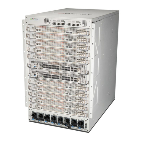
You can install up to 14 FortiGate-5000 series boards in the 14 slots of the FortiGate-5144C ATCA chassis. The
FortiGate-5144C is a 14U 19-inch rackmount ATCA chassis that contains four redundant hot swappable DC power entry
Modules (PEMs). The PEMs connect to -48V DC power and supply 400 W to each chassis front slot. The FortiGate-
5144C chassis also includes four hot swappable cooling fan trays that provide 450W of cooling power per slot and a
front replaceable air filter with redundant pressure sensors. If all 14 slots contain FortiGate-5001D boards, the
FortiGate-5144C chassis provides a total of 28 FortiGate 40Gbps Ethernet interfaces and 28 FortiGate 10Gbps
interfaces.
Using the dual star 40Gbps fabric and 1Gbps base backplane interfaces the FortiGate-5144C chassis can support a
wide range of different configurations. For example:
lUp to 14 FortiGate-5001D boards in chassis slots 1 to 14, each board operating as a separate FortiGate firewall.
lOne or two FortiController-5913C boards in chassis slots 1 and 2 in a dual-star configuration to support a 100 Gbps
session-aware load balancing cluster (SLBC) that distributes traffic to up to 12 FortiGate-5001D boards (called
workers)installed in chassis slots 3 to 14.
lOne or two FortiController-5903C boards to support a 40 Gbps SLBC with up to 12 FortiGate-5001D workers.
lOne or two FortiController-5913C or FortiController-5903C boards in chassis slots 1 and 2 can also be used for
FortiGate-5144C fabric and base backplane switching and to support FGCP clustering.
lTwo FortiController-5103B boards can be installed in slots 1 and 2 to create an SLBC for FortiGate-5001D (or older)
workers. FortiController-5103B boards can also be used for fabric and base backplane switching and to support
FGCP clustering.
lTwo FortiController-5902D boards can be installed in slots 1 and 2 to support content clustering to load balance
traffic to multiple FortiGate-5001D workers.
The FortiGate-5144C chassis requires -48V DC power. If DC power is not available you can install a FortiGate-5053B
power supply shelf and PSU-5000B power supplies (purchased separately).
FortiGate-5144C front panel
The following illustration shows the front of a FortiGate-5144C chassis containing two FortiController-5903C boards are
installed in slots 1 and 2 and 12 FortiGate-5001D boards installed in slots 3 to 14.
These components are also visible on the front of the FortiGate-5144C chassis:
lThe primary and secondary Shelf Managers. Fortinet ships theFortiGate-5144C chassis with the primary shelf
manager installed. You can purchase and install a secondary shelf manager for redundancy. The shelf manager
provides power allocation, cooling, alarms, shelf status, displays alarms and includes a telco alarm interface.
lThe location of the front-replaceable air filter frame and retention screws.
lThe location of hot swappable fan trays 1 and 2 (can be accessed by opening the top cover at the front of the
chassis).
lThe Electrostatic discharge (ESD) socket, used for connecting an ESD wrist band when working with the chassis.
FortiGate-5144C 6.2.3 Chassis Guide 7
Fortinet Technologies Inc.
FortiGate-5144C Chassis Fortinet Technologies Inc.
Do not operate the FortiGate-5144C chassis with open slots on the front or back panel. For
optimum cooling performance and safety, each chassis slot must contain either a FortiGate-
5000 series board or an air baffle slot filler. For the same reason, all cooling fan trays and the
air filter should be installed while the chassis is operating. As well all four PEMs (two primary
and two redundant) must be installed in the back of the chassis.
Example FortiGate-5144C front panel
FortiGate-5001D
boards
slots 4, 6, 8, 10,
12, and 14
FortiGate-5001D
boards
slots 3, 5, 7, 9,
11, and 13
FortiController-5903C
boards
slots 1 and 2
ESD
socket
Slot
numbers
Fan Tray 1 (front) Fan Tray 2 (front)
Primary Shelf Manager Secondary Shelf Manager
Air filter
frame
FortiGate-5144C back panel
The FortiGate-5144C chassis back panel includes access to hot swappable fan trays 3 and 4.
The FortiGate-5144C chassis back panel includes four -48V to -60 VDC power entry modules (PEMs). Fortinet ships the
FortiGate-5144C chassis with all four installed. The PEMs are divided into two power feeds. PEMs 1 and 2 make up
feed A. PEMs 3 and 4 make up power feed B. To provide power to the chassis you must connect the PEMs in feed A. To
provide redundant power you can also connect the PEMs in feed B.
FortiGate-5144C 6.2.3 Chassis Guide 8

FortiGate-5144C Chassis Fortinet Technologies Inc.

Each PEM has two power feeds (feed 1 and feed 2) that include a -48V/-60 VDC terminal (labeled -) and a RTN terminal
(labeled +). To connect a PEM, both of its feeds must be connected to DC power.
The back panel also contains 14 RTM slots numbered to correspond to the front panel slots. When the chassis is
shipped, these slots are covered by RTM air baffle slot covers.
The back panel includes the FortiGate-5144C chassis ground connector that must be connected to ground.
Example FortiGate-5144C chassis back panel
!
!
Chassis
ground
connector
PEM 1
Feed AFeed B
PEM 2PEM 3PEM 4
RTM
slot numbers
Fan Tray 4 (back) Fan Tray 3 (back)
RTM
air baffle
slot covers
Chassis hardware information
This section introduces FortiGate-5144C hardware components and accessories including power requirements and
FortiGate-5000 series boards that can be installed in the chassis.
FortiGate-5144C 6.2.3 Chassis Guide 9

FortiGate-5144C Chassis Fortinet Technologies Inc.
Shipping components
The FortiGate-5144C chassis ships pre-assembled with the following components:
lThe 14U FortiGate-5144C chassis
lOne shelf manager installed in the front of the chassis
lFour Power Entry Modules (PEMs) installed in the back of the chassis
lOne air filter installed behind the air intake bezel at the bottom of the chassis
lFour cooling fans installed in the fan bays at the top of the chassis
l13 front panel air baffle slot covers installed in the front panel slots
l14 RTM air baffle slot covers installed in the RTM slots
lEight 4-ft. power cables with 8 AWG stranded wires and double-hole lugs: Black for -48VDC and red for RTN.
These cables should only be used to connect the FortiGate-5144C PEMs to a FortiGate-5053B power convertor
shelf if purchased with your FortiGate-5144C chassis
lOne USB to RJ-45 RS-232 console cable
lOne RJ-45 Ethernet cable
lRack mount template (labeled metal strips showing how to line up cage nuts with rack holes when installing the
chassis)
l5 spare nuts and washers for the PEM power studs
l20 cage nuts with M6 screws
l1 Philips No.2 screw driver
l1 flat (4mm) screw driver
l1 socket wrench (10mm)
lCage nut installation tool
Accessories
lSupported Fortinet ATCA boards
lShelf Manager
lShelf FRU data module
Supported Fortinet ATCA boards
You can install the following FortiGate-5000 series boards in a FortiGate-5144C chassis to provide security services.
The FortiGate-5144C chassis has been added to the FortiGate-5000 product family to support recent and future
FortiGate-5000 series boards with high power requirements. This includes the following:
ATCA board Interfaces Function Power
Used (W)*
Heat
Dissipation
(BTU/hr)*
FortiGate-5001B Front Panel: 8 x 10 Gbps
Fabric: 10 Gbps
FortiOS network security Max: 225
Ave: 187
768
FortiGate-5001C Front Panel: 2 x 10 Gbps FortiOS network security Max: 225 768
FortiGate-5144C 6.2.3 Chassis Guide 10

FortiGate-5144C Chassis Fortinet Technologies Inc.
ATCA board Interfaces Function Power
Used (W)*
Heat
Dissipation
(BTU/hr)*
Fabric: 10 Gbps Ave: 187
FortiGate-5101C Front Panel: 4 x 10 Gbps
Fabric: 10 Gbps
FortiOS network security Max: 236
Ave: 197
805
FortiGate-5001D Front Panel: 2 x 40 Gbps,
2 x 10 Gbps, or
split into 8 x 10 Gbps
Fabric: 40 Gbps or 10Gbps
FortiOS network security Max: 226
Ave: 189
774
FortiGate-5001E
FortiGate-5001E1
Front Panel: 2 x 40 Gbps,
2 x 10 Gbps, or
split into 8 x 10 Gbps
Fabric: 40 Gbps or 10Gbps
FortiOS network security Max: 278
Ave: 250 948
FortiSwitch-5203B Front Panel: 8 x 10 Gbps
Fabric: 10 Gbps
Content clustering with
FortiGate-5001Bs
Max: 250
Ave: 210
853
FortiController-5902D
Front Panel: 4 x 40 Gbps or
split into 16 x 10 Gbps
Fabric: 40 Gbps or 10 Gbps
Content clustering with
FortiGate-5001Ds
Max: 270
Ave: 223
919
FortiSwitch-5003B Front Panel: 8 x 10 Gbps
Fabric: 10 Gbps
Backplane switching,
FGCP HA, and extended
load balancing (ELBC)
Max: 180
Ave: 150
614
FortiController-5103B Front Panel: 8 x 10 Gbps, or
8 x 1 Gbps
Fabric: 10 Gbps or 1 Gbps
Session-aware load
balancing Clustering
(SLBC) and FGCP HA
Max: 255
Ave: 213
754
FortiController-5903C Front Panel: 4 x 40 Gbps or
split into 16 x 10 Gbps
Fabric: 40 Gbps or 10 Gbps
Session-aware Load
Balancing Clustering
(SLBC) and FGCP HA
Max: 400
Ave: 250
1360
FortiController-5913C Front Panel: 2 x 100 Gbps
or split into 20 x 10 Gbps
Fabric: 40 Gbps or 10 Gbps
Session-aware Load
Balancing Clustering
(SLBC) and FGCPHA
Max: 400
Ave: 280
955
*Approximate values, see product datasheets for official values.
Any Fortinet ATCA board can be installed in the FortiGate-5144C chassis including the following older models:
lFortiGate-5001A
lFortiCarrier-5001A
lFortiGate-5005FA2
lFortiGate-5001FA2
lFortiGate-5001
lFortiGate RTM-XB2
lFortiGate RTM-XD2
lFortiSwitch-5003A
FortiGate-5144C 6.2.3 Chassis Guide 11

FortiGate-5144C Chassis Fortinet Technologies Inc.
Power requirements
The FortiGate-5144C is rated to draw up to 153A. Each of the four PEM feeds/terminals draws up to 39A with -48VDC
input and 450W/slot (400W front and 50W RTM). If no RTM slots are used, the total current will be up to 138.5A and
with up to 35A per feed with -48VDC input. (the draw from the 4 feeds may not be even.)
The FortiGate-5144C chassis is designed to be installed in a Telecom or data center or similar location that has
available -48VDC power fed from a listed circuit breaker (also called battery power or main DC power). Fortinet expects
that mostFortiGate-5144C customers will be installing their chassis in a location that is already equipped with a -48VDC
power system fed from a listed circuit breaker that provides power to existing networking or telecom equipment. The
FortiGate-5144C chassis is designed to be connected directly to this DC power system.
If DC power is not available you can use one or more FortiGate-5053B power converter shelves equipped with PSU-
5000B power supplies to convert AC to DC to supply DC power to the FortiGate-5144C chassis from an AC source.
Physical description of the FortiGate-5144C chassis
The FortiGate-5144C chassis is a 14U chassis that can be installed in a standard 19-inch rack. The following table
describes the physical characteristics of the FortiGate-5144C chassis.
Dimensions (H x W x D) 24.44 x 19.06 x 21.63 in. (62.10 x 48.40 x 54.96 cm)
Shipping weight and size completely
assembled with packaging
165 lbs (75 kg) (36 x 31 x 27in) (91 x 78 x 69cm)
Chassis weight completely assembled with
shelf manager and air baffles
(13 front and 14 RTM) 108 lbs (50 kg)
PEM DC terminal torque No more than 3.8 Nm (33.62 lbf.in)
Operating environment Temperature (long term): 32 to 104°F (0 to 40°C)
Temperature (short term): 23 to 131°F (-5 to 55°C)
Relative humidity: 20 to 90% (Non-condensing)
Power consumption Min: 150W, Max: 1000 W (Power consumed by an empty
chassis with four fans, one shelf manager and four PEMs
installed and operating with the fans running at full speed.)
Heat dissipation 150W to 1000W (512 BTU/hr and max 3412 BTU/hr)
Power input 4x to 2 PEMs (2 per PEM) with 2x redundant PEMs -48 Vdc/-
60Vdc, 153A/122A
Overcurrent protection Each PEM includes 4 power channels. Each channel includes
its own 30 A fuse.
Cooling capacity 450 W per slot (Front slot 400 W and RTM slot 50 W)
Protected earth test EN60950-1, test current 25 A, resistance <100 mOhm
Hipot test EN60950-1, 1000 V
FortiGate-5144C 6.2.3 Chassis Guide 12

FortiGate-5144C Chassis Fortinet Technologies Inc.
FortiGate-5144C shelf managers
The FortiGate-5144C chassis includes one or two redundant hot-swappable shelf managers, located in the dedicated
shelf manager slots at the bottom of the front panel. The primary shelf manager is installed on the left the secondary
shelf manager (if present) is installed on the right. The secondary shelf manager is optional.
FortiGate-5144C shelf manager front panel
Ethernet
Interface
RS-232
Serial
Out of Service (Red),
Active (Green),
and Hot Swap (Blue) LEDs
Hot Swap
Button Reset
Button
Alarm Cut Off
Button
Backplane
Ethernet Link LEDs
Retention
Screw
Fan Tray
LEDs
Telco Alarm
Interface
Retention
Screw
Critical Alarm (Red)
Major Alarm (Red)
Minor Alarm (Amber)
Power OK (Green)
Fortinet ships the FortiGate-5144C chassis with the primary shelf manager installed. You can purchase a secondary
shelf manager for redundancy.
If your chassis has two shelf managers, they support redundant operation with automatic switchover. If both shelf
managers are operating normally, one acts as the active shelf manager and the other as the backup. You can tell
which shelf manager is active by the state of the shelf manager front panel ACT(Active) LED. This LED is solid green for
the active shelf manager and flashing green for the backup shelf manager.
The active shelf manager performs all shelf manager functions. The shelf managers monitor each other and if the active
shelf manager stops communicating (for example because it has failed or is restarting) the backup shelf manager
becomes the active shelf manager. When the failed or restarting former active shelf manager comes back up it will
detect that the other shelf manager is active and become the backup shelf manager. Also, if one shelf manager fails or
is removed the other will operate independently as the active shelf manager and the chassis will continue to function
normally.
The active Shelf Manager communicates with Intelligent Platform Management Controllers (IPMCs) in the chassis,
each of which is responsible for local management of one or more Field Replaceable Units (FRUs), such as boards, fan
trays or power entry modules. Management communication within a chassis occurs primarily over the Intelligent
Platform Management Bus (IPMB), which is implemented using radial bus technology.
The active shelf manager controls chassis power allocation, monitors chassis operating parameters, monitors and
controls chassis cooling, and generates alarms if the chassis encounters problems. The active shelf manager also
displays alarms and includes a telco alarm interface. All FortiGate-5000 boards installed in the chassis communicate
with the active Shelf Manager through the IPMCs.
The shelf managers are hot swappable. You remove a shelf manager by pressing and holding the hot swap button. The
hot swap LED starts blinking blue. When the hot swap LED turns solid blue you can loosen both retention screws and
remove the shelf manager from the chassis.
FortiGate-5144C 6.2.3 Chassis Guide 13

FortiGate-5144C Chassis Fortinet Technologies Inc.
Connecting to the Shelf manager and shelf manager Ethernet channels
Each shelf manager has an RS-232 serial port for connecting to the shelf manager console CLI. For information about
using this port, see Connecting to the shelf manager CLI using the shelf manager console port on page 36.
Each shelf manager also includes an Ethernet switch that connects the shelf manager front panel Ethernet interface and
the shelf manager base channel backplane Ethernet interface.The switch has two Ethernet channels, ETH0 and ETH1:
lETH0 connects to the shelf manager Ethernet switch. This switch splits ETH0 into 2 independent channels. One
channel connects to both shelf manager front panel Ethernet interfaces and the other connects to the chassis
backplane base channel SH1.
lETH1 connects the Shelf manager directly to the chassis backplane base channel SH2.
Shelf Manager Ethernet switch and ETH0 and ETH1 architecture
The factory default shelf manager ETH0 port IP address is 192.168.0.2. You can change this IPaddress from the shelf
manager CLI. If your chassis has one shelf manager it will be installed in the primary shelf manager slot and you can
communicate with it by connecting the shelf manager's front panel Ethernet interface (ETH0) or to the B1 or B2 interface
of a hub or switch board installed in chassis slot 1 or 2.
If your chassis has two shelf managers (one in the primary shelf manager slot and one in the secondary shelf manager
slot) either one of them can be the active shelf manager. From an external device you can only connect to the active
shelf manager. You should connect the front panel Ethernet interface (ETH0) of both shelf managers to your network.
That way, no matter which shelf manage is active you can still connect to the active shelf manager using the shelf
manager IP address (default 192.168.0.2). You can change the active Shelf Manager's IP address from the shelf
manager CLI. You can also connect to the active shelf manager from the B1 or B2 interface of a hub or switch board
installed in chassis slot 1 or 2
You cannot connect to the backup shelf manager from an external device and you normally don't have to. However, if
you want to connect to the backup shelf manager you can log into the active shelf manager and then Telnet to
192.168.1.3. This is the fixed internal IP address of the backup shelf manager and is normally only used to allow
communication between the active and backup shelf managers.
If a failover occurs the active shelf manager's IP address will be transferred to the new active shelf manager. The new
backup shelf manager will have the internal IP address of 192.168.1.3.
FortiGate-5144C 6.2.3 Chassis Guide 14

FortiGate-5144C Chassis Fortinet Technologies Inc.
Shelf manager Ethernet connections to chassis slots (and boards)
The following diagram shows how the shelf managers connect to the chassis slots. Each shelf manager has two
connections to the chassis; one to each of the hub slots. ETH0 connects to SH1 of one chassis slot and ETH1 connects
to SH2 of the other chassis slot.
Shelf Manager Ethernet cross-connections and connections to chassis slots
Changing the shelf manager switch configuration to prevent Ethernet loops
Because ETH0 connects to both shelf manager front panel Ethernet interface and to the chassis backplane base
channel via the shelf manager onboad Ethernet switch, it is possible to create an Ethernet loop if you connect the shelf
FortiGate-5144C 6.2.3 Chassis Guide 15

FortiGate-5144C Chassis Fortinet Technologies Inc.
manager front panel interfaces and the B1 or B2 interface of a switch board in slot 1 or 2 to same network. So
connecting these interfaces to the same network is not recommended.
The most recent version of the shelf manager firmware (version 3.4.2.4G) is factory set to disable the connection
between the shelf manager switch and the backplane. This means that you must connect to the shelf manager front
panel Ethernet interface to manage the shelf manager. This also means that if you connect the shelf manager front
panel interfaces and the B1 or B2 backplane to the same network you will not get looping.
Firmware version 3.4.2.4G includes the ShMC_Eth_Switch_config command that can be used to change the
switch configuration. The command has four options:
lget_EEPROM_config displays the current switch configuration.
lset_default_EEPROM sets the switch to the default switch configuration. The default configuration enables
BOTH the front panel and the backplane interfaces.
ldisable_backplane_port disables the connection to the backplane. This option is factory set by Fortinet.
ldisable_front_panel_port disables the connection to the front panel Ethernet interface.
Entering these commands (except for get_EEPROM_config) reboots the shelf manager. If your chassis has two shelf
managers if you enter one of these commands to change the configuration you must enter the command on each shelf
manager. When you enter a command the active shelf manager reboots and while this is happening the backup shelf
manager becomes the active shelf manager.
FortiGate-5144Cshelf manager LEDs
LED State Description
FT1-4 OOS (Fan Tray 1-4 out
of service)
Off Fan tray 1 to 4 is operating normally.
Red Fan tray 1 to 4 is out of service.
OOS (Out of Service) Off Normal Operation.
Red Shelf manager software reboot or other failure.
ACT (Active) Solid Green Indicates that this is the active shelf manager.
Blinking Green Indicates that this is the backup shelf manager.
H/S (Hot Swap) Off Normal operation.
Blinking Blue The shelf manager is shutting down in preparation for being
removed from the chassis.
Blue The shelf manager can be removed from the chassis.
LA2 (backplane port 1) Green Backplane ethernet port 1 connected.
Blinking Network activity on backplane ethernet port 1.
LS2 (backplane port 1) Amber 100 Mbit Link on backplane ethernet port 1.
Off 10 Mbit Link on backplane ethernet port 1.
LA1 (backplane port 0) Green Link on backplane ethernet port 0.
Blinking Network activity on backplane ethernet port 0.
FortiGate-5144C 6.2.3 Chassis Guide 16

FortiGate-5144C Chassis Fortinet Technologies Inc.
LED State Description
LS1 (backplane port 0) Amber 100 Mbit Link on backplane ethernet port 0.
Off 10 Mbit Link on backplane ethernet port 0.
10/100 (Front panel ethernet
port)
Amber 100 Mbit link on Front Panel Ethernet Port 0.
Off 10 Mbit link on Front Panel Ethernet Port 0.
L/A (Front panel ethernet port) Green Front Panel Ethernet Port 0 connected.
Blinking Network activity on Front Panel Ethernet Port 0.
CRITICAL (Major Alarm) Red Critical alarm detected in chassis.
MAJOR (Major Alarm) Red Major alarm detected in chassis.
MINOR (Minor Alarm) Amber Minor alarm detected in chassis.
POWER OK Green Input power to the chassis is within limits.
FortiGate-5144Cshelf manager Buttons
Button Description
H/S (Hot Swap) Start the hot swap procedure. Push and the H/S LED blinks. Hold until H/S is solid blue
then remove shelf manager.
RST (Reset) Reset the shelf manager.
CUTOFF (Telco Alarm
Cut Off)
Reset alarm contacts when alarm LEDs are blinking.
Radial IPMB bus topology
The FortiGate-5144C backplane includes a redundant dual star radial IPMB bus for higher reliability. Each shelf
manager provides 14 unique IPMB0-A and 14 unique IPMB0-B links to the 14 chassis slots. This means 28 IPMB
channels per shelf manager. The radial topology is shown below.
FortiGate-5144C 6.2.3 Chassis Guide 17

FortiGate-5144C Chassis Fortinet Technologies Inc.
Radial IPMB bus topology
Using the shelf manager CLI
You can use the shelf manager command line interface (CLI) to communicate with the intelligent management
controllers of the chassis, with boards in the chassis, and with the shelf manager itself. The CLI is an IPMI-based set of
commands that can be accessed directly or through a higher-level management application or a script. Using the CLI,
you can access information about the current state of the chassis including current board population, current sensor
values, threshold settings, recent events, and overall chassis health.
To get started using the shelf manager CLI, see Shelf Manager CLI on page 36.
Shelf Manager fan and power control
The FortiGate-5144C shelf managers monitor the internal temperature of the chassis and adjust the operating speed of
the cooling fans as required.
When the chassis is first powered on all cooling fans run at full speed. Once the shelf manager is up and running, the
shelf manager reduces cooling fan speeds to maintain an optimum temperature in the chassis. If shelf managers are
not installed or not operating correctly the FortiGate-5144C chassis cooling fans always operate at full speed.
Telco alarms
The Telco Alarm Interface is a standard DB-15 male Telco Form-c connector. The external dry relay Telco alarm
interface (48VDC) provides Telco form-c relay connections for minor, major and critical power faults. The cable required
to connect to the alarm interface is not supplied by Fortinet. To monitor alarms you should connect to the telco alarm
interface of the active shelf alarm panel, which by default is the one on the left.
The Telco alarm interface relay circuits are capable of carrying 60 VDC or 1 A with a max. rating of 30 VA. The shelf
alarm panel accepts timed pulse inputs for clearing minor and major alarm states. Reset is accomplished by asserting a
voltage differential from 3.3 V to 48 V for between 200 and 300 ms. The acceptance voltage range is from 0 to 48 VDC
continuous (handles up to 60 VDC at a 50% duty cycle). The current drawn by a reset input does not exceed 12 mA.
FortiGate-5144C 6.2.3 Chassis Guide 18

FortiGate-5144C Chassis Fortinet Technologies Inc.
The alarm LED reset button activates the alarm cutoff (ACO) state for major, minor, and user-defined alarms. You
cannot reset critical alarms with the alarm LED reset button.
When the ACO state is activated, active alarm LEDs blink and all of the alarm relays are deactivated. The alarm reset
button activates the ACO state but does not clear the alarm completely.
The telco alarm connector (DB-15 male)
Telco alarm connector pin assignment
Pin Descrption
1 MinorReset+
2 MinorReset-
3 MajorReset+
4 MajorReset-
5 CriticalAlarm - NO
6 Critical Alarm NC
7 Critical Alarm COM
8 Minor Alarm NO
9 Minor Alarm NCT
10 Minor Alarm COM
11 Major Alarm NO
12 Major Alarm NC
13 Major Alarm COM
14 Power NO
15 Power COM
Air Filter
The FortiGate-5144C chassis includes a front replaceable air filter that removes dust from intake air and provides static
pressure to achieve uniform airflow. The filter must be installed for the chassis to operate normally. If the air filter is not
locked into place the air filter presence sensors cause an alarm.
FortiGate-5144C 6.2.3 Chassis Guide 19

FortiGate-5144C Chassis Fortinet Technologies Inc.
The air filter should be inspected regularly. If dirty or damaged, the filter should be disposed of and replaced. The air
filter can be fragile and should be handled carefully.
To service the air filter you must loosen two the air filter frame retention screws at the bottom of the front of the chassis.
Tilt down the air filter frame and remove the air filter material.
Care should be taken when inserting an new air filter to prevent damage to the sensors. To insert a new filter, slide it
into the frame using the guides at each side of frame until the filter contacts springs at the back of the chassis. Then tilt
the frame up and tighten the retention screws.
Cooling fans, cooling air flow, and minimum clearance
The FortiGate-5144C chassis contains four hot-swappable cooling fans (fan 1 to fan 4) installed in the fan cabinet at the
top of the chassis. Two fans are access able from the front of the chassis and two from the back.
Fan tray locations (top view of chassis)
Front of Chassis
Back of Chassis
Right
Left
Fan 3 Fan 4
Fan 1 Fan 2
Front and back fan trays
!
!
Back Fan Tray
(Fan Trays 3 and 4)
Front Fan Tray
(Fan Trays 1 and 2)
To service the front fan trays (fan trays 1 and 2), open the front fan cabinet. The back fan trays (fan trays 3 and 4), are
accessible from the back of the chassis. The fan trays are hot swappable. You do not need to press a hot swap switch to
remove a fan. Just pull a fan out of the chassis and replace it. The shelf manager regulates the fan speed by adjusting
the DC voltage supplied to the fan trays.
FortiGate-5144C 6.2.3 Chassis Guide 20
This manual suits for next models
2
Table of contents
Other Fortinet Chassis manuals

Fortinet
Fortinet FortiGate FortiGate-5050 User manual

Fortinet
Fortinet FortiGate-5060 User manual

Fortinet
Fortinet FortiGate-7000F Series Parts list manual

Fortinet
Fortinet FortiGate-5000 Use and care manual

Fortinet
Fortinet FortiGate-5140B User manual

Fortinet
Fortinet FortiGate FortiGate-5140 User manual

Fortinet
Fortinet FortiGate FortiGate-5140 User manual
Popular Chassis manuals by other brands

Advantech
Advantech IPC-6806S user manual

Enterasys
Enterasys Matrix N3 7C103 Hardware installation guide

Avaya
Avaya Virtual Services Platform 9000 Series Installation

Philips
Philips L04LAA Service manual

National Instruments
National Instruments NI PXI-1031 user manual

nox
nox Hummer Vault installation guide