GMI D6014S User manual

D6014 - SIL 3 Repeater Power Supply G.M. International ISM0210-2
SIL 3 Repeater Power Supply
Hart, DIN-Rail and Termination Board,
Models D6014S, D6014D
D6014S - D6014D
INSTRUCTION MANUAL

2 D6014 - SIL 3 Repeater Power Supply G.M. International ISM0210-2
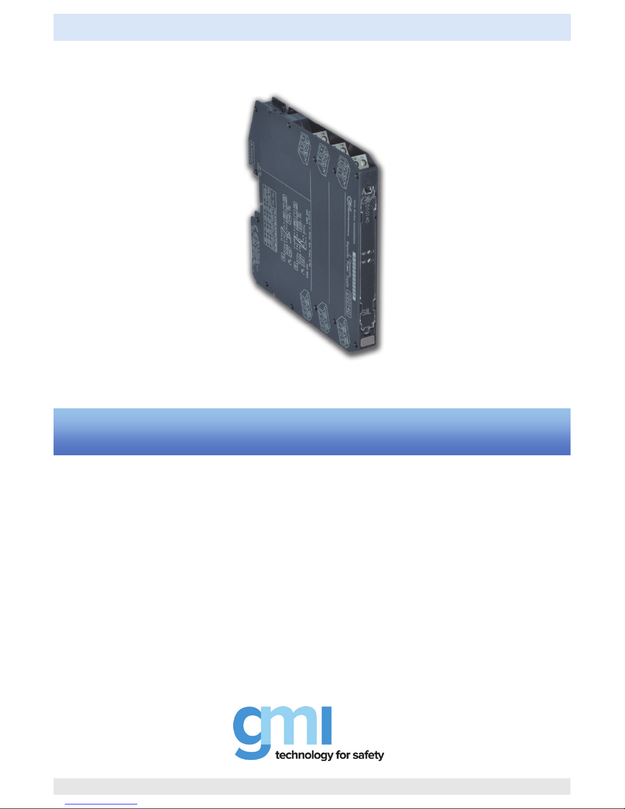
General Description: The single and dual channel Repeater Power Supply, D6014S and D6014D module is a high integrity analog input interface suitable for applications
requiring SIL 3 level (according to IEC 61508:2010 Ed.2) in safety related systems for high risk industries. Provides a fully floating dc supply for energizing conventional
2 wires 4-20 mA, active or passive, transmitters and repeats the current in floating circuit to drive a load.
The circuit allows bi-directional communication signals, for Hart transmitters.
Mounting on standard DIN-Rail, with or without Power Bus, or on customized Termination Boards.
Functional Safety Management Certification:
G.M. International is certified by TÜV to conform to IEC61508:2010 part 1 clauses 5-6 for safety related systems up to and included SIL3.
Technical Data
Characteristics
Supply: 24 Vdc nom (18 to 30 Vdc) reverse polarity protected, ripple within voltage limits 5 Vpp, 2 A time lag fuse internally protected.
Current consumption @ 24 V: 90 mA for 2 channels D6014D, 45 mA for 1 channel D6014S with 20 mA output typical.
Power dissipation: 1.35 W for 2 channels D6014D, 0.675 W for 1 channel D6014S with 24 V supply voltage and 20 mA output typical.
Isolation (Test Voltage): In/Out 2.5 KV; In/Supply 2.5 KV; In/In 500 V; Out/Supply 500 V; Out/Out 500 V.
Input: 4 to 20 mA (separately powered input, voltage drop 0.5 V) or 4 to 20 mA (2 wires Tx current limited at 25 mA), reading range 0 to 24 mA.
Transmitter line voltage: 15.0 V typical at 20 mA with max. 20 mVrms ripple on 0.5 to 2.5 KHz frequency band, 14.5 V minimum.
Output: 4 to 20 mA, on max. 550 load in source mode (typical 12 V compliance);
V min. 8 V at 0 load V max. 30 V in sink mode, current limited at 25 mA or
1 to 5 V on internal 250 shunt (or 2 to 10 V on internal 500 shunt on request).
Response time: 5 ms (0 to 100 % step change).
Output ripple: 20 mVrms on 250 communication load on 0.5 to 2.5 KHz band.
Frequency response: 0.5 to 2.5 KHz bidirectional within 3 dB (Hart protocol).
Performance: Ref. Conditions 24 V supply, 250 load, 23 ± 1 °C ambient temperature.
Calibration accuracy: ± 0.1 % of full scale.
Linearity error: ± 0.05 % of full scale.
Supply voltage influence: ± 0.02 % of full scale for a min to max supply change.
Load influence: ± 0.02 % of full scale for a 0 to 100 % load resistance change.
Temperature influence: ± 0.01 % of full scale on zero and span for a 1 °C change.
Compatibility:
CE mark compliant, conforms to Directive: 2014/30/EU EMC, 2014/35/EU LVD, 2011/65/EU RoHS.
Environmental conditions:
Operating: temperature limits – 40 to + 70 °C, relative humidity 95 %, up to 55 °C.
Storage: temperature limits – 45 to + 80 °C.
Approvals:
TÜV Certificate No. C-IS-722134640-01, SIL 2 / SIL 3 conforms to IEC61508:2010 Ed.2.
TÜV Certificate No. C-IS-236198-09, SIL 3 Functional Safety Certificate conforms to IEC61508:2010 Ed.2, for Management of Functional Safety.
Mounting:
T35 DIN-Rail according to EN50022, with or without Power Bus or on customized Termination Board.
Weight: about 155 g D6014D, 130 g D6014S.
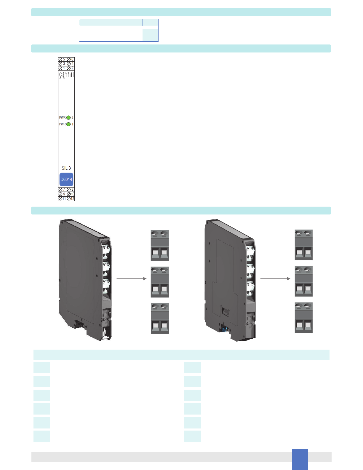
Connection: by polarized plug-in disconnect screw terminal blocks to accomodate terminations up to 2.5 mm2.
Protection class: IP 20.
Dimensions: Width 12.5 mm, Depth 123 mm, Height 120 mm.
FSM
SIL 3

3
D6014 - SIL 3 Repeater Power SupplyG.M. International ISM0210-2
Ordering Information
Front Panel and Features
SIL 3 according to IEC 61508:2010 Ed.2 for Tproof = 1 / 10 yrs (10% / >10 % of total SIF).
SIL 2 according to IEC 61508:2010 Ed.2 for Tproof = 14 / 20 yrs (10% / >10 % of total SIF).
PFDavg (1 year) 6.69 E-05, SFF 90.47 %.
Systematic capability SIL 3
2 fully independent channels.
4-20 mA Input / Output Signal Active-Passive / Source-Sink
Hart compatible.
Input and Output short circuit proof.
High Accuracy.
Three port isolation, Input/Output/Supply.
EMC Compatibility to EN61000-6-2, EN61000-6-4, EN61326-1, EN61326-3-1 for safety system.
In-field programmability by DIP Switch.
TÜV Certification.
TÜV Functional Safety Certification.
High Density, two channels per unit.
Simplified installation using standard DIN-Rail and plug-in terminal blocks, with or without Power Bus, or customized Termination Boards.
Terminal block connections
2 1
4 3
6 5
Model: D6014
1 channel S
2 channels D
Power Bus and DIN-Rail accessories:
Connector JDFT049 Cover and fix MCHP196
Terminal block male MOR017 Terminal block female MOR022
7 8
9 10
11 12
+ Input Ch 1 for 2 wires Transmitters
- Input Ch 1 for 2 wires Transmitters or
+ Input Ch 1 for External Powered Transmitters
+ Input Ch 2 for 2 wires Transmitters
- Input Ch 2 for 2 wires Transmitters or
+ Input Ch 2 for External Powered Transmitters
- Input Ch 1 for External Powered Transmitters
- Input Ch 2 for External Powered Transmitters
7
8
9
10
11
12
+ Output Ch 1
1
- Output Ch 1
2
+ Output Ch 2
3
- Output Ch 2
4
+ Power Supply 24 Vdc
5
- Power Supply 24 Vdc
6

4 D6014 - SIL 3 Repeater Power Supply G.M. International ISM0210-2
Function Diagram
==
=
5 +
6 -
1
2RLmA
+
-
HHT Source I
Out 1 (SIL 3)
3
4RLmA
+
-
Source I
Out 2 (SIL 3)
HHT
7
11
+
-
HHT
2 Wire Tx
I
?
+
-
External
Powered Tx
In 1
10
12
+
-
2 Wire Tx
+
-
External
Powered Tx
In 2
HHT
I
?
8
9
MODEL D5014D
+
-Termination
board
connector
Power Bus
==
=
=
=
=
=
Supply 24 Vdc
mA +
V
Source V Sink I
+
-
+
-
RL
mA +
V
Source V Sink I
+
-
+
-
RL
==
=
5 +
6 -
1
2RLmA
+
-
HHT Source I
Out (SIL 3)
Supply 24 Vdc
7
11
+
-
HHT
2 Wire Tx
I
?
+
-
External
Powered Tx
In
8
MODEL D5014S
=
=
+
-Termination
board
connector
Power Bus
mA +
V
Source V Sink I
+
-
+
-
RL
MODEL D6014S
MODEL D6014D

5
D6014 - SIL 3 Repeater Power SupplyG.M. International ISM0210-2
Function Diagram
Connections for Duplication of 2 wires Transmitter Input
Restriction on specifications for 2 wires Transmitter Input:
Bidirectional communication for Smart Transmitter is provided only on channel 1
The minimum supply voltage available for Transmitter (Vtx) is 14 V at 20 mA input
==
=
5 +
6 -
1
2RLmA
+
-
HHT Source I
Out 1 (SIL 3)
3
4RLmA
+
-
Source I
Out 2 (SIL 3)
7
11
10
12
8
9
MODEL D5014D Duplicator
+
-Termination
board
connector
Power Bus
==
=
=
=
=
=
Supply 24 Vdc
+
-
HHT
2 Wire Tx
I
?
In 1
mA +
V
Source V Sink I
+
-
+
-
RL
mA +
V
Source V Sink I
+
-
+
-
RL
MODEL D6014D Duplicator

6 D6014 - SIL 3 Repeater Power Supply G.M. International ISM0210-2
Function Diagram
Connections for Duplication of Active Input Signal
Restriction on specifications for external powered Transmitter:
==
=
5 +
6 -
1
2RLmA
+
-
Source I
3
4RLmA
+
-
Source I
7
11
10
12
8
9
MODEL D5014D Duplicator
+
-Termination
board
connector
Power Bus
==
=
=
=
=
=
Supply 24 Vdc
+
-
External
Powered Tx
In 1
Out 2 (SIL 3)
mA +
V
Source V Sink I
+
-
+
-
RL
mA +
V
Source V Sink I
+
-
+
-
RL
Out 1 (SIL 3)
Voltage drop 1.0 V
MODEL D6014D Duplicator

7
D6014 - SIL 3 Repeater Power SupplyG.M. International ISM0210-2
D6014 series must be installed, operated and maintained only by qualified personnel, in accordance to the relevant national/international installation standards.
Failure to properly installation or use of the equipment may risk to damage the unit or severe personal injury.
The unit cannot be repaired by the end user and must be returned to the manufacturer or his authorized representative. Any unauthorized modification must be avoided.
Warning
Operation
D6014 provides fully floating DC supply for energizing 2 wires 4-20 mA transmitters, or separately powered 4 wires, 4-20 mA transmitters and repeats and converts the current to
a 4-20 mA or 1-5 V floating output signal to drive a load.
The circuit allows bi-directional communication signal for smart transmitters, a “POWER ON” green led for each channel lits when input power is present.
Installation
D6014 series are repeater power supply hart compatible housed in a plastic enclosure suitable for installation on T35 DIN-Rail according to EN50022, with or without Power Bus or
on customized Termination Board.
D6014 unit can be mounted with any orientation over the entire ambient temperature range.
Electrical connection of conductors up to 2.5 mm² are accommodated by polarized plug-in removable screw terminal blocks which can be plugged in/out into a powered unit without
suffering or causing any damage.
The wiring cables have to be proportionate in base to the current and the length of the cable.
On the section “Function Diagram” and enclosure side a block diagram identifies all connections.
Identify the number of channels of the specific card (e.g. D6014S is a single channel model and D6014D is a dual channel model), the function and location of each connection terminal
using the wiring diagram on the corresponding section, as an example:
Connect 24 Vdc power supply positive at terminal “5” and negative at terminal “6”.
For Model D6014S connect positive output of channel 1 at terminal “1” and negative output at “2”.
For Model D6014D in addition to channel 1 connections above, connect positive output of channel 2 at terminal “3” and negative output at “4”.
For Model D6014S, in case of a 2 wires Transmitter, connect the wires at terminal “7” for positive and “8” for negative.
For separately powered Transmitters connect input signal at terminal “8” for positive and “11” for negative.
For Model D6014D in addition to channel 1 connections above, connect terminal “9” for positive and “10” for negative on channel 2.
Connect input signal from separately powered Transmitters at terminals “10” for positive and “12” for negative on channel 2.
Units must be protected against dirt, dust, extreme mechanical (e.g. vibration, impact and shock) and thermal stress, and casual contacts.
If enclosure needs to be cleaned use only a cloth lightly moistened by a mixture of detergent in water.
Any penetration of cleaning liquid must be avoided to prevent damage to the unit. Any unauthorized card modification must be avoided.
According to EN61010, D6014 series must be connected to SELV or SELV-E supplies.
Start-up
Before powering the unit check that all wires are properly connected, particularly supply conductors and their polarity, input and output wires.
Check conductors for exposed wires that could touch each other causing dangerous unwanted shorts. Turn on power, the “power on” green leds must be lit, for 2 wires transmitter
connection the supply voltage on each channel must be 14.5 V, output signal should be corresponding to the input from the transmitter. If possible change the field transmitter output
and check the corresponding module output.

8 D6014 - SIL 3 Repeater Power Supply G.M. International ISM0210-2
ON
D6014D
ON
D6014S
Configuration
Dip switch configuration
1234
ON
Ch1 4-20 mA
Source Mode
678
5
1234 678
5
1234 678
5
1234 678
5
Ch1 4-20 mA
Sink Mode
Ch2 4-20 mA
Source Mode
Ch2 4-20 mA
Sink Mode
Ch2 1-5 V
(on 250 ---
internal shunt)
Ch1 1-5 V
(on 250 ---
internal shunt)
ON ON OFF OFF
ON
ON ONON
OFF OFF OFF
OFF
ON ON OFF OFF
ON
ON ON
ON
OFF OFF OFF
OFF
Dip switch configuration
An output configuration DIP Switch is located on component side of pcb. This switch allows the mA (sink or source mode) or Volt operating mode configuration.
1234
ON
4-20 mA
Source Mode
1234
1234
1234
4-20 mA
Sink Mode
1-5 V (on 250 ---
internal shunt)
ON ON
ON
ONONON
OFF OFF
OFFOFFOFF
OFF
Source mode is factory settings
Only Source/Sink mode can be
used for SIL applications.
Source mode is factory settings
Only Source/Sink mode can be
used for SIL applications.
This manual suits for next models
1
Table of contents
Other GMI Power Supply manuals
Popular Power Supply manuals by other brands

Monster Power
Monster Power HDP 2400 owner's manual

cytiva
cytiva EPS 3501 XL operating instructions

Rigol
Rigol DP831A Performance Verification Manual

Vertiv
Vertiv NetSure 5100 installation manual

Delta Electronics
Delta Electronics DPS-180KB-4 Series Specifications

Beckhoff
Beckhoff PS2031-2410-0000 installation manual