EspañolEnglish
INSTALLATION INSTRUCTIONS INSTRUCCIONES DE INSTALACIÓN
En caso de presiones de funcionamiento superiores
a 5 BARES (~75 PSI), se aconseja el uso de un
reductor de presión.
Antes de efectuar el montaje, se aconseja purgar
las tuberías del agua caliente y fría para evitar
que suciedad y pequeñas impurezas afecten el
funcionamiento del grifo.
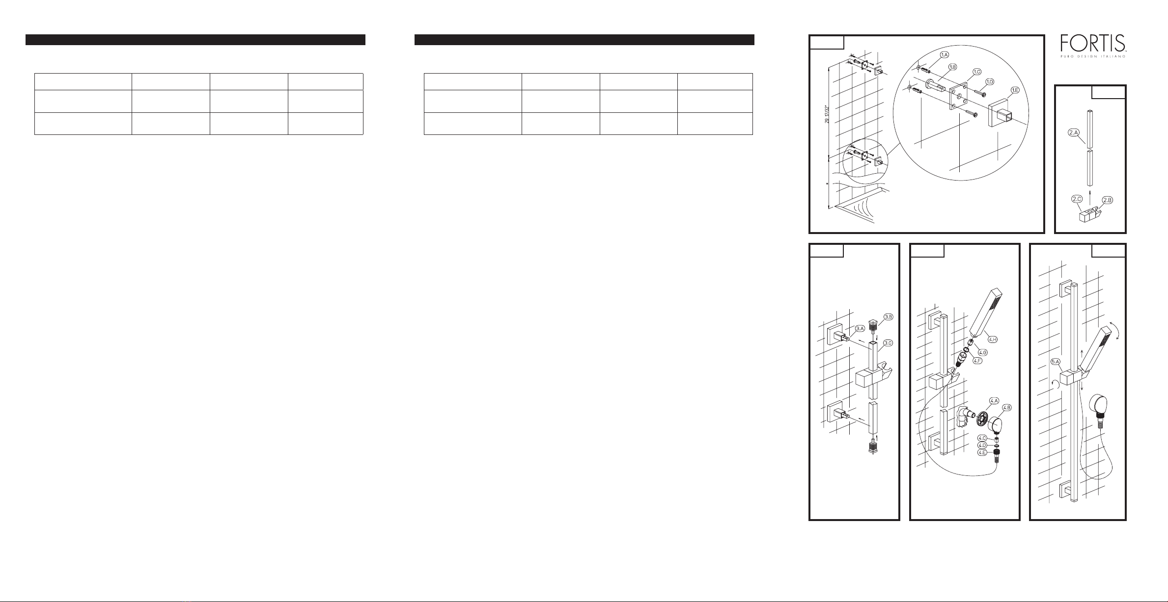
FIG. 01 - PREPARACIÓN DE LA PARED
Para preparar la instalación en la pared, posicionar
la barra deslizante a la altura deseada, para obtener
la referencia del orificio inferior ( * ), y marcar con
un lápiz. Medir en la parte superior, empezando
de la marca que se acaba de hacer, la posición
del segundo orificio a la distancia de 29-17/32” y
marcar con un lápiz.
Apoyar la placa (1.C) en la pared, haciendo
coincidir una de las dos marcas de lápiz con el
orificio central de la misma; marcar, siempre con
un lápiz, la posición de dos de los cuatro orificios
de la placa (es recomendable marcar dos orificios
diagonalmente opuestos). Repetir la operación
también para la otra referencia colocada a 29-
17/32”. Realizar un orificio en las últimas cuatro
referencias e introducir los tarugos en dotación (1.A)
Con los tornillos (1.D) fijar a pared la placa (1.C)
interponiendo entre esta y la pared el perno (1.B).
Aplicar el florón (1.E) en la placa, haciéndolo entrar
en contacto con la pared.
FIG. 02 - INSTALACIÓN BARRA DESLIZANTE
Introducir el soporte de ducha deslizante (2.B) en la
barra deslizante (2.A) y fijarlo en la misma girando
la maneta (2.C) en 90°.
FIG. 03 - INSTALACIÓN TOMA AGUA Y
DUCHA DE TELÉFONO
Aplicar la barra deslizante (3.C) en los pernos
(3.A), luego introducir los tapones (3.B) en la misma
fijando todo el conjunto.
FIG. 04 - INSTALACIÓN TOMA AGUA Y DUCHA
DE TELÉFONO
Para la instalación de la toma de agua a pared
(4.B), montar previamente la junta (4.A) y atornillar a
pared utilizando teflón o sellante de roscas.
In case of pressures over 5 BAR (~75 PSI), we
recommend to use a pressure reducer.
Before proceeding with the assembly, purge
the hot and cold water pipes so as to avoid the
accumulation of dirt and impurities that could
affect the function of the faucet.
FIG. 01 - PREPARATION OF THE
INSTALLATION WALL
To prepare the wall for installation, position
the sliding bar at the desired height and mark
with a pencil the position of the lower hole ( *
). Measure and mark the position of the second
hole at a distance of 29-17/32” starting from the
previously made reference point.
Fit the plate (1.C) on the wall aligning one of the
two marks with the central hole of the plate; mark
the position of two of the four plate holes with a
pencil (we recommend marking two diagonally
opposite holes). Repeat the operation for the other
reference at 29-17/32”. Drill a hole on the four
remaining marks and insert the screw anchors
(1.A)
Fasten the plate (1.C) to the wall using the screws
(1.D) and placing the peg (1.B) between the
plate and the wall. Install the square rosette (1.E)
on the plate till it is flush to the wall.
FIG. 02 - INSTALLATON OF THE SLIDING BAR
Fit the sliding shower bracket (2.B) on the sliding
bar (2.A) and lock it by rotating the handle (2.C)
by 90°.
FIG. 03 - WATER INLET AND HAND
SHOWER INSTALLATION
Install the sliding bar (3.C) on the pegs (3.A), then
fit and fasten the plugs (3.B) on the bar.
FIG. 04 - INSTALLATION OF THE WATER
SUPPLY AND HAND SHOWER
To install the wall-mount water supply (4.B),
pre-assemble the gasket (4.A) and screw the
Based on its policy of steady development Fortis reserves the right to change the characteristics
of the products without notice and therefore the images and data contained in this catalogue may vary.
Por su política de continuo desarrollo, Fortis se reserva el derecho de modificar las características de los productos sin ningún aviso
previo; por tanto, las imágenes y los datos contenidos en el presente catálogo deben considerarse a título indicativo.
Antes de montar el flexible de la ducha asegurarse
de que la válvula antirretroceso (4.C) esté montada
en el interior de la toma de agua.
Atornillar el flexible de la ducha (4.E) interponiendo
entre éste y la toma de agua (4.B) la junta de
G1/2” (4.D).
Efectuar la misma operación para la ducha teléfono
(4.H), asegurarse de que esté presente la válvula
limitadora 2.2 GPM (4.G), atornillar el flexible (4.E)
a la ducha teléfono (4.H) interponiendo la junta de
G1/2” (4.F).
FIG. 05 - REGULACIÓN SOPORTE DESLIZANTE
Regular la posición de la ducha teléfono según las
propias exigencias, como se indica en la figura.
Para regular la altura del soporte de la ducha es
necesario girar 90° la maneta (5.A) en el sentido
indicado por la flecha; efectuar la operación inversa
para fijar todo el conjunto.
MANTENIMIENTO Y CONSEJOS TÉCNICOS Y
PRÁCTICOS
SUSTITUCIÓN DE FLEXIBLE, DUCHA TELÉFONO
O VÁLVULAS
Para efectuar la sustitución de la ducha teléfono
por mal funcionamiento, el flexible de la ducha
porque se ha dañado, o las válvulas antirretroceso
y limitadora, proceder en sentido inverso respecto a
las instrucciones descritas en la FIG.04.
MANTENIMIENTO DE LAS SUPERFICIES
Durante la limpieza, la superficie del grifo debe
estar fría (el calor acelera el desgaste de la
superficie misma). Asegurarse de que los productos
para la limpieza no contengan ácidos o sustancias
corrosivas. El grifo debe ser secado diariamente
con un paño suave. Evitar absolutamente esponjas
de acero, esponjas abrasivas u otros productos
similares. Inmediatamente después de la limpieza,
enjuagar bien los residuos de detergente con agua
fría. Los daños a los grifos debidos a un tratamiento
no adecuado no están cubiertos por la garantía.
assembly on the wall using some Teflon or thread
sealing paste.
Before assembling the shower flex pipe make
sure the check valve (4.C) has been installed
inside the water supply.
Fasten the shower flex pipe (4.E) placing the
G1/2” gasket (4.D) between the pipe and the
water supply (4.B).
Repeat this operation to assemble the hand
shower (4.H) making sure the 2.2 GPM limiting
valve (4.G) is fitted, screw the flex pipe (4.E) on
the hand shower (4.H) placing the G1/2” gasket
(4.F) in between.
FIG. 05 - SLIDING BAR ADJUSTMENT
Adjust the position of the hand shower based on
the user’s needs, as shown.
To adjust the height of the shower bracket rotate
the handle (5.A) by 90° in the direction shown by
the arrow; rotate in opposite direction to fasten
the assembly.
MAINTENANCE AND TECHNICAL HINTS
FLEX PIPE, HAND SHOWER AND VALVE
REPLACEMENT
In case of malfunctions or damage to the hand
shower, check valves and limitation valves,
replace the item following the instructions
described in FIG. 04 in reverse order.
MAINTENANCE OF THE SURFACES
Before cleaning, make sure the faucet is cold (heat
wears the surface of the faucet down). Do not use
products containing acids or corrosive substances.
Wipe the faucet daily with a soft cloth. Do not use
steel wool or metal pads, abrasive sponges or
similar products. Right after cleaning rinse off the
detergent residues with cold water. Damages to
the faucets caused by incorrect treatment are not
covered by the warranty.
FIG. 01
FIG. 02
FIG. 05
Water Supply Recommended Maximum Minimum
Hot Water Temperature 65 C° (~150F) 80 C° (~175F) 15 C° (~60F)
Working Pressure 3 BAR (~45PSI) 5 BAR (~75PSI) 0.5 BAR (~7PSI)
Alimentación Recomendada Máxima Mínima
Temperatura agua
caliente
65 C° (~150F) 80 C° (~175F) 15 C° (~60F)
Presión de
funcionamiento
3 BARES (~45PSI) 5 BARES (~75PSI) 0.5 BARES (~7PSI)
FIG. 03 FIG. 04
Istruz. art. 8412900.indd 4-6 28/04/10 11:49


