Fortress Technologies LI675 User manual

FTS 610
January 3, 1996
1
FTS 610
January 3, 1996
Replacing the Batteries in the Fortress
LI675, LI750, LI 950 and LI 1020 Models
This FTS describes how to replace the batteries in Fortress®LI675, LI750, LI 950 and LI 1020 models. Battery replacement
will take about 30 minutes.
Batteries should be replaced by a qualified service person. If you have any questions or problems, please call Powerware’s
Worldwide Service at 1-800-356-5737. (Outside of the U.S. and Canada, call 1-608-565-2100).
To replace the batteries, you will need the following (use insulated tools):
•Needlenose Pliers
•Black Electrical Tape
•Phillips Screwdriver
•1/4-inch Hex Nutdriver
•Torx Screwdriver
•True RMS Digital Multimeter
•Safety Equipment Required by Local Codes
•Optional Items:
•
¾Inspection Mirror
¾Small Flashlight
¾Wood Dowel (about 7 inches long) or Wood Pencil
Before you go on to Section 1, read the important safety warnings.
Contents Index
Section 1: Removing the Fortress’ Cover.......................................................................................................................3
Section 2: Removing the Batteries .................................................................................................................................3
Section 3: Replacing the Batteries in the Fortress..........................................................................................................5
Section 4: Putting the Cover on the Fortress ..................................................................................................................6
IMPORTANT SAFETY INSTRUCTIONS – SAVE THESE INSTRUCTIONS
This publication contains important instructions that should be followed during battery replacement.

FTS 610
January 3, 1996
2
CAUTION
Read the following cautions before you go on to step 1:
The batteries used in this system are capable of producing dangerous voltages and high currents. They may
cause severe injury if terminals are shorted together or to ground (earth). Extreme care must be taken to avoid
electrical shock and burns caused by contacting battery terminals or shorting terminals during battery
replacement.
Powerware’s batteries come with a one-year warranty. Using batteries not supplied Powerware invalidates any
BEST/Powerware service agreement.
A qualified service person who is familiar with the Fortress should replace the batteries; replacing the batteries requires
the service person to remove the batteries and put them back in place. The service person must take these precautions:
1. Before you remove the UPS cover, always remove or shut off all sources of AC power and shut off the UPS. You
must turn the UPS On/Off (1/0) switch to Off (0) and remove the input power cord to make sure AC voltage will
not be present in the Fortress.
2. Whenever the UPS On/Off switch is on, there will be AC voltage inside the UPS and at the UPS receptacles; this
is true because the UPS can supply power from AC line or from its batteries. To avoid equipment damage or
personal injury, always assume that there may be voltage inside the UPS
3. All UPS units contain hazardous AC and DC voltages. Because of these voltages, a qualified service person must
replace the circuit board.
4. Protective clothing and eye wear must be warn. Batteries contain caustic acids and toxic materials and can rupture
or leak if mistreated. Remove rings and metal wristwatches or other jewelry. Don’t carry metal objects in pockets
where they can fall into the UPS.
5. Tools must be insulated so that they will not short battery terminals. At no time can a tool be allowed to short a
battery terminal to another battery terminal or to the UPS cabinet. Do not lay tools or metal parts on top of the
batteries.
6. When connecting cables, never allow a cable to short across a battery’s terminals or the string of batteries or to the
UPS cabinet.
7. Align the cables on the battery terminals so that the connector will not contact any part of the UPS cabinet even if
the battery is moved. Keep the cable away from any sharp metal edges.
8. Install the battery cables so they cannot be pinched by the UPS cabinet.

FTS 610
January 3, 1996
3
Section 1: Removing the Fortress’ Cover
1. Before you replace the batteries, you must shut off and unplug the equipment protected by the Fortress.
2. Next, follow these three steps:
•Turn the On/Off (I/O) switch on the back of the Fortress off (to O).
•Unplug the Fortress.
•Remove the power cord from the back of the UPS.
3. Carefully turn the Fortress on its side and look at the bottom of the UPS. Remove the four screws and washers in
the corners. (See Figure 1 below.)
4. Stand the Fortress on its feet again.
5. Slide the UPS cover back until it comes off.
Section 2: Removing the Batteries
1. Remove the four screws that secure the battery access panel on the back of the
Fortress. (See Figure 2.) Remove the battery access panel.
CAUTION: Do not put your fingers between batteries or between a
battery and the UPS’ cabinet. When you slide the batteries,
use the wood dowel to hold the battery cables so they won’t
catch on the UPS’ cabinet or other parts.
2. See Figure 3 on the next page. Slide the batteries toward the back of the UPS until
the negative (black) cable is about two inches away from the cabinet.
3. Taking care not to tear the insulation on the connector, disconnect the negative
(black) cable using the needlenose pliers. (See Figure 3 on the next page for cable
location.)
CAUTION: Put a piece of electrical tape over the metal end of the negative (black) cable so it cannot
accidentally touch another metal part.
Note: The gray cable attached to the negative cable is not connected.
FTS 610
January 3, 1996
4
4. Now, turn the On/Off switch on the back of the Fortress on (to 1) for about four seconds to discharge the capacitor.
(The capacitor is discharged when the display and lights are no longer lit.)
Then, turn the switch off again.
CAUTION!
Make sure you turn the switch off before you continue. When you connect the new batteries, there will
be dangerous voltage inside the UPS if the On/Off switch is on (I). This is true because the UPS battery
supplies power even if the UPS is not connected to its AC input source.
5. Disconnect the jumper cable using the needlenose pliers (see Figure 3 for cable location).
CAUTION: Put a piece of electrical tape over the metal end of the jumper cable so it cannot accidentally
touch another metal part.
Make sure that the terminals do not touch the cabinet or any metal part. Assume that the
batteries are fully charged, and use the same precautions you would use when handling
new batteries.
6. Slide the first battery out of the cabinet.

FTS 610
January 3, 1996
5
7. Remove and save the separator (thin cardboard or foam) that is between the two batteries. Slide the second battery
towards the back of the UPS until the positive (red) cable is about two inches away from the cabinet.
8. Using the needlenose pliers, disconnect the positive (red) cable and the jumper cable from the battery (see Figure
3 on page 4 for cable location).
Read the caution below; then, lift out the batteries.
CAUTION: Make sure that the terminals do not touch the cabinet or any metal part. Assume that the
batteries are fully charged, and use the same precautions you would use when handling
new batteries.
Batteries contain lead. Dispose of old batteries properly. Do not dispose of batteries in a
fire; the battery may explode. Do not open or mutilate batteries. Released electrolyte is
harmful to the skin and eyes. It may be toxic.
Section 3: Replacing the Batteries in the Fortress
1. Check to see if your Fortress has “battery bumpers” installed on the cabinet where the batteries sit. If there are no
cabinet battery bumpers, go to step 2.
If your UPS has cabinet bumpers installed, check to see if the new batteries have bumpers installed on the top.
Remove the bumpers from the batteries since the batteries will not fit in the cabinet if there are bumpers in both
places.
2. Route the positive (red) and negative (black) battery cables from the printed circuit board through the grommet and
into the bottom of the cabinet.
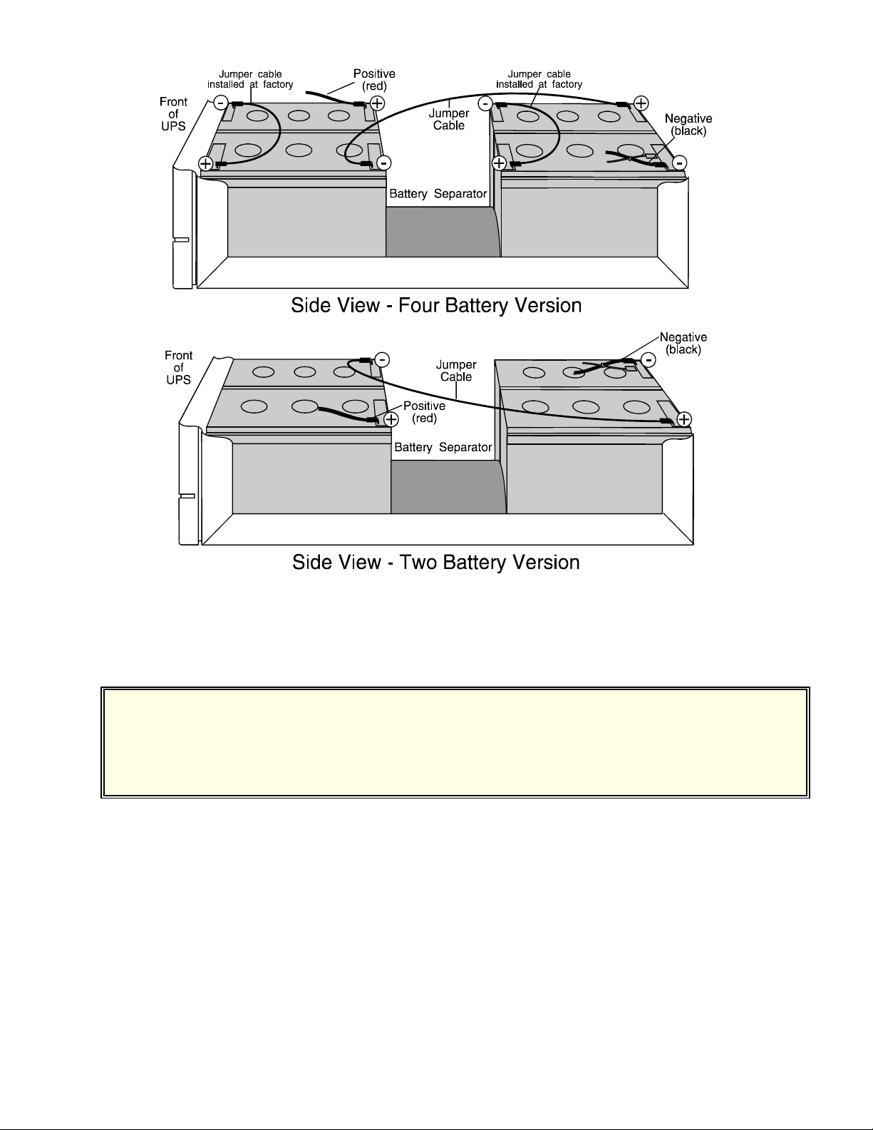
3. If you are installing batteries in the “Four Battery Version,” make sure that the factory-installed jumper wires on
the batteries rest flat against the top of each battery. (See Figure 3 on page 4.) If necessary, use tape to hold the
factory jumper down so that it does not catch on cabinet parts as you slide the batteries in. If you are installing
batteries in the “Two Battery Version,” there are no factory-installed jumpers because there are only two batteries.
CAUTION: Do not put your fingers between two batteries or between a battery and the UPS’ cabinet.
When you slide the batteries, use the wood dowel to hold the battery cables so they won't
catch on the UPS’ cabinet or other parts.
4. Connect the negative end of the jumper cable and the positive (red) battery cable to the first battery and slide it
halfway into the UPS cabinet. Figure 3 shows how the batteries should be arranged and where the battery terminals
should be. Be sure to refer to the “Four Battery Version” if your four batteries have external factory-installed
jumpers. If you have two batteries without external jumpers, use the “Two Battery Version.”
CAUTION: Make sure the positive (red) cable goes to the red terminal and the black jumper cable goes
to the black terminal as shown on the selected diagram.
5. Put the separator between the two batteries.
6. Slide the second battery part of the way into the UPS cabinet. Leave about two inches of room to make the final

FTS 610
January 3, 1996
6
connections.
7. Remove the tape and connect the end of the jumper cable with the positive (+) label to the positive (+) terminal of
the battery.
8. Make sure the On/Off switch is still in the Off (0) position. Find the gray cable attached to the negative (black)
cable. Hold the gray cable’s connector to the remaining battery terminal for five seconds. (Do not leave the gray
cable permanently connected.) This recharges the capacitor so there will not be an arc when you connect the
negative battery cable.
9. Now, remove the tape from the negative (black) cable and connect the negative cable to the second battery.
10. Put a piece of tape over the metal end of the gray cable. The gray cable can then rest on top of the second battery.
11. Check the UPS from either side to make sure there are no wires in or blocking the air fan inlet. The air fan inlet is
in the metal cabinet above the spacer between the batteries.
12. Turn the On/Off switch on (to 1). The yellow Battery light on the front panel should be on, showing that the unit
is running on inverter. Measure the output voltage at the Fortress’ output receptacles to make sure the Fortress
provides the proper output voltage.
13. Turn the On/Off switch off (to 0). Plug the power cord back into the Fortress.
14. Plug in the Fortress and turn the On/Off switch on (to 1). Make sure the unit switches to AC Line power. (The green
Line light should light and the yellow Battery light should go out.)
15. Turn the Fortress off, remove the power cord, and go on to the next section.
Section 4: Putting the Cover on the Fortress
1. Put the battery access panel on the back of the Fortress and install the four screws that secure the panel. (See Figure
2 on page 3.)
2. As you put the cover back on the UPS, make sure the vent holes are on the side opposite the circuit boards. To secure
the cover, carefully turn the Fortress on its side and put the four cover screws back in the bottom of the UPS.
3. Stand the Fortress on its feet again.
4. Plug the Fortress’ power cord back into the UPS and the input receptacle.
5. To finish the procedure, follow these steps:
a. Turn off the loads (the equipment the Fortress protects) and plug them into the UPS’ receptacles.
b. Turn the Fortress’ On/Off switch on (to 1), and switch on the equipment plugged into the UPS.
This manual suits for next models
3
Table of contents
Other Fortress Technologies Batteries Pack manuals


