Fortress Technologies LI 660 User manual

FTS 609
November 17, 1993
Replacing the Batteries in the Fortress LI 660
This FTS describes how to replace the batteries in Fortress LI 660 units.
Batteries should be replaced by a qualified technician. If you have any questions or problems,
please call Powerware Global Services at 800-356-5737. (Outside of the U.S. and Canada, call
your local Powerware office.)
To replace the batteries, you will need the following:
•Needle Nose Pliers
•Black Electrical Tape
•Phillips Screwdriver — 6” long below handle*
*Note: The screwdriver should be six inches long below the handle so you can
replace the inside screws easily. Using a magnetic screwdriver makes removing and
replacing the screws easier.
Before you go on to Section 1, read the important safety warnings on the next page.
Contents Index
1. Removing the Fortress’ Cover......... ............ ............ ........................ ............ ............ ............2
2. Removing the Batteries....... ............ ............ ............ ........................ ............ ............ ............3
3. Replacing the Batteries ....... ............ ............ ............ ........................ ............ ............ ............5
4. Replacing the Fortress’ Cover ......... ............ ............ ........................ ............ ............ ............6
IMPORTANT SAFETY INSTRUCTIONS - SAVE THESE INSTRUCTIONS
This publication contains important instructions that should be followed during battery
replacement.
WARNING
The batteries used in this system are capable of producing dangerous voltages and high
currents. They may cause severe injury if terminals are shorted together or to ground
(earth). Extreme care must be taken to avoid electrical shock and burns from contacting
battery terminals or shorting terminals during battery replacement.
Powerware’s batteries come with a one-year warranty. Using batteries not supplied by
Powerware invalidates any BEST/Powerware service agreement.

FTS 609
November 17, 1993
2
A qualified technician who is familiar with the Fortress should replace the batteries. The
technician must take these precautions:
1. Protective clothing and eye wear must be worn. Batteries contain caustic acids and toxic
materials and can rupture or leak if mistreated. Remove rings and metal wristwatches or
other jewelry. Don’t carry metal objects in pockets where they can fall into the UPS.
2. Tools must be insulated so that they will not short battery terminals. At no time can a tool
be allowed to short a battery terminal to another battery terminal or to the UPS cabinet.
Do not lay tools or metal parts on top of batteries.
3. When connecting cables, never allow a cable to short across a battery’s terminals or the
string of batteries or to the UPS cabinet.
4. Align the cables on the battery terminals so that the connector will not contact any part of
the UPS cabinet even if the battery is moved. Keep the cable away from any sharp metal
edges.
5. Install the battery cables so they cannot be pinched by the UPS cabinet.
Section 1: Removing the Fortress’ Cover
1. Before you replace the batteries, shut off the equipment plugged into the Fortress and unplug the
equipment.
2. Next, follow these three steps:
•Turn the On/Off (1/0) switch on the back of the Fortress off (to 0).
•Unplug the Fortress.
•Remove the power cord from the back of the UPS.
3. Carefully turn the Fortress on its side, and look at the bottom of the UPS. Remove the four screws and
washers in the corners (shown in Figure 1 below). Note: Some models do not have washers.
Figure 1
FTS 609
November 17, 1993
3
4. Stand the Fortress on its feet again.
5. Slide the UPS cover back until it comes off.
Section 2: Removing the Batteries
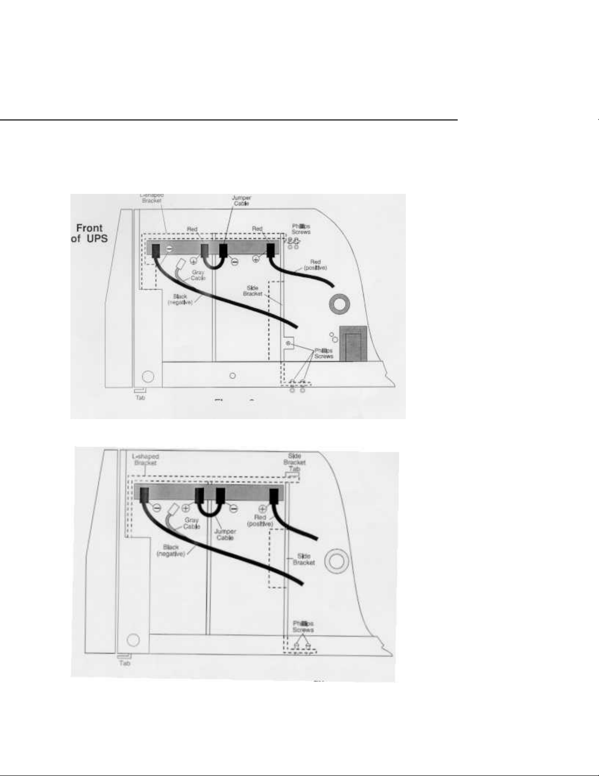
The figures on the next page show the batteries and battery connections. If the two battery
brackets in your Fortress are fastened together with two Phillips screws, use Figure 2. If the
two battery brackets in your Fortress are attached together with a tab and slot, use Figure 3.
Figure 2

FTS 609
November 17, 1993
4
Figure 3
Check the figure for your UPS and continue with step 6.
6. Using the needle nose pliers, disconnect the negative (black) cable from the battery by
gently pulling the connector down, away from the battery terminal. (See the figure that
shows your UPS for terminal locations.) Note: The gray cable attached to the negative
cable is not connected.
Put a piece of black electrical tape over the end of the black cable so it cannot
accidentally touch another metal part.
7. Now, turn the On/Off switch on the back of the Fortress on (to 1) for about four seconds
to discharge the capacitor. (The capacitor is discharged when the display and lights are
no longer lit.) Then, turn the switch off again.
WARNING!
Make sure you turn the switch off before you continue. When you connect the new
batteries, there will be dangerous voltage inside the UPS if the On/Off switch is on.
This is true because the UPS battery supplies power even if the UPS is not connected
to its AC input source.
8. Use the needle nose pliers to remove the short jumper cable connecting the batteries
together (see the figure that shows your UPS).
9. Disconnect the positive (red) cable using the needle nose pliers (see your figure for the
cable’s location).
Put a piece of black electrical tape over the end of the red cable so it cannot
accidentally touch another metal part.
10. If your UPS looks like Figure 2, follow the steps in the first column below.
If your UPS looks like Figure 3, follow the steps in the second column below.
Read the caution below before you remove the batteries from the UPS.
Caution: Make sure that the battery terminals do not touch the cabinet or any metal
part. Assume that the old batteries are fully charged, and use the same precautions you would
use when handling new batteries. Batteries contain lead. Dispose of the old batteries properly.
Do not dispose of a battery or batteries in a fire; the battery may explode. Do not open or
mutilate batteries. Released electrolyte is harmful to the skin and eyes. It may be toxic.

FTS 609
November 17, 1993
5
If your UPS looks like Figure 2: If your UPS looks like Figure 3:
a. To reduce the chance of shorting across the battery
terminals, put a piece of electrical tape over one terminal on
each battery
b. Refer to Figure 2 to find the Phillips screws holding
the battery brackets in place. Remove all five screws
and washers.
c. Remove the side bracket first. To remove the
bracket, slide it carefully away from the batteries and
lift it out.
Now, remove the top (L-shaped) bracket. (Note:
Some units do not have an L-shaped bracket; instead,
these units have a bracket that fits on top of the
batteries. Remove this bracket.)
d. Before you remove the old batteries, note the
arrangement of the batteries and their terminals. When
you put the new batteries in (in step 11), use the same
arrangement.
e. Lift the old batteries out of the unit.
a. To reduce the chance of shorting across the battery
put a piece of electrical tape over one terminal on each
battery
b. Refer to Figure 3 to find the Phillips screws holding the
battery brackets in place. Remove both screws.
c. Before you remove the old batteries, note the
the batteries and their terminals. When you put the new
batteries in (in step 11), use the same arrangement.
d. Remove both brackets and both batteries at one
time.
First, slide the batteries and brackets to the right until
you can lift the bottom tabs of the L-shaped bracket
through the slots in the bottom of the unit.
Next, grasp both batteries firmly. Lift the batteries and
brackets up about one inch. Then, carefully pull the
and brackets toward yourself (not upward) to remove
from the unit. (There is just enough space between the
cabinet frame and the heatsink to pull the batteries
Section 3: Replacing the Batteries
11. If your UPS looks like Figure 2, follow the steps in the first column below.
If your UPS looks like Figure 3, follow the steps in the second column below.
If your UPS looks like Figure 2: If your UPS looks like Figure 3:
a. To reduce the chance of a short across the battery
terminals, put a small piece of electrical tape
over each of the terminals.
b. Put the new batteries in place. Figure 2 shows how the
batteries should be arranged and where the
battery terminals should be.
c. Put in the L-shaped bracket that goes over the top and
one side of the batteries. Make sure that the L-
shaped bracket fits into the two slots in the
bottom of the UPS; then, put the side bracket
back in place.
a. To reduce the chance of a short across the battery
terminals, put a small piece of electrical tape over each
of the terminals.
Place both batteries and both brackets into the unit at
one time.
b. Assemble the brackets and batteries before placing
them into the unit.
Place the side bracket’s tab through the slot nearest the edge
of the L-shaped bracket. Slide the brackets over the
batteries. Figure 3 shows how the batteries and brackets

FTS 609
November 17, 1993
6
NOTE: If you do not have an L-shaped bracket, put the
top bracket back in. To do this, put the tab in the
top bracket in the slot in the front of the UPS.
d. Now, use the five Phillips screws to attach the side
bracket to the L-shaped bracket, the bottom of the UPS,
and the side of the UPS.
Put the top two screws in first.
Use the two shortest screws to attach the side bracket to
the bottom of the UPS.
e. Remove the electrical tape from the battery terminals.
should be arranged and where the battery terminals should
be.
c. Grasp both batteries firmly. Carefully place the
batteries and brackets back into the unit. Then, fit the
tabs on the L-shaped bracket into the two slots in the
bottom of the UPS.
d. Press the side bracket snugly against the batteries; then,
use the two Phillips screws to attach the side bracket to
the bottom of the UPS.
e. Remove the electrical tape from the battery terminals.
12. Before you connect any battery cables, make sure the On/Off switch on the back of the unit
is still off.
13. Remove the tape from the red cable and use the needle nose pliers to reconnect the red
cable to the terminal marked “Red (positive)” on the figure for your UPS.
14. Reconnect the short jumper cable as shown in the figure for your UPS.
15. Find the black (negative) cable attached to a gray cable.
16. Next, hold the gray cable’s connector to the remaining battery terminal for five seconds.
(Do not connect the gray cable.) This recharges the capacitor so there will not be an arc
when you connect the negative battery cable.
17. Now, remove the tape from the black cable and use the needle nose pliers to connect the
black cable to the negative (black) terminal.
Section 4: Replacing the Fortress’ Cover
As you put the cover back on the UPS, make sure the vent holes are on the side opposite the
circuit boards. To secure the cover, carefully turn the Fortress on its side and put the four
cover screws back in the bottom of the UPS.
19. Stand the Fortress on its feet again.
20. Plug the Fortress’ power cord back into the UPS and the input receptacle.

FTS 609
November 17, 1993
7
21. Turn the Fortress On/Off switch on (to 1). To make sure the UPS’ battery is fully
charged, let the UPS charge the battery for at least 6.5 hours. (The battery charges
automatically whenever the “Line” light is on.)
22. To finish the procedure, follow these three steps:
•Turn the Fortress On/Off switch off (to 0).
•Turn off the loads (the equipment the Fortress protects) and plug them into the UPS’
receptacles.
•Turn the Fortress On/Off switch on (to 1), and switch on the equipment plugged into
the UPS.
Table of contents
Other Fortress Technologies UPS manuals


