Smart power SBP Plus Series User manual

USER'S GUIDE
Uninterruptible
Power Supply
SBP Plus Series
(Venus Plus)
Models:
SBP PLUS UPS Series
SBP450U Plus-T,SBP650U Plus-T,
SBP800U Plus-T,SBP1000U Plus-T,
SBP1500U Plus-T
450-1500

1
This manual contains important instructions for models SBP450UPlus-T,
SBP650UPlus-T, SBP800UPlus-T, SBP1000UPlus-T, SBP1500UPlus-T that should be
followed during installation and maintenance of the UPS and batteries.
Read this manual thoroughly before attempting to unpack, install, or operate your UPS.
CAUTION! To prevent the risk of fire or electric shock, install in a temperature and
humidity controlled indoor area free of conductive contaminants. (See the
specifications for the acceptable temperature and humidity range.)
CAUTION! To reduce the risk of overheating the UPS, do not cover the UPS' cooling
vents and avoid exposing the unit to direct sunlight or installing the unit near heat
emitting appliances such as space heaters or furnaces.
CAUTION! Do not attach non-computer-related items,such as medical
equipment,life-support equipment, microwave ovens, or vacuum cleaners to UPS.
CAUTION! Do not plug the UPS input into its own output.
CAUTION! Do not allow liquids or any foreign object to enter the UPS. Do not place
beverages or any other liquid-containing vessels on or near the unit.
CAUTION! In the event of an emergency, press the OFF button and disconnect the
power cord from the AC power supply to properly disable the UPS.
CAUTION! Do not attach apower strip or surge suppressor to the UPS.
CAUTION! Internal battery voltage is 12Vdc.Sealed,lead-acid,6-cell battery.
CAUTION! Servicing of batteries should be performed or supervised by personnel
knowledgeable of batteries and the required precautions. Keep unauthorized
personnel away from batteries.
CAUTION! When replacing the batteries, use the same number and type of batteries.
CAUTION! Do not dispose of batteries in afire.The battery may explode.Do
not open or mutilate the battery or batteries. Released electrolyte is harmful to the skin
and eyes.
CAUTION! Unplug the UPS prior to cleaning and do not use liquid or spray detergent.
CAUTION! A battery can present a risk of electric shock and high short circuit current.
The following precaution should be observed before replacing batteries: (1) Remove
watches, rings, or other metal objects.(2) Use tools with insulated handles.(3) Wear
rubber gloves and boots.(4) Do not lay tools or metal parts on top of batteries. (5)
Disconnect charging source prior to connecting or disconnecting batteries terminal.
• When replacing batteries, replace with the same number of the sealed lead-acid
batteries.
Safety Cautions!

2
Ce manuel contient des instructions importantes pour les modèles
à suivre lors de
l'installation et de la maintenance de l'onduleur et des batteries. Lisez attentivement ce
manuel avant de déballer, d’installer ou d’utiliser votre système UPS.
Précautions de sécurité!
MISE EN GARDE! Pour éviter tout risque d’incendie ou de choc électrique, installez-le
dans une zone intérieure à température et humidité contrôlées, exempte de contaminants
conducteurs. (Voir les spécifications pour la plage de température et d'humidité
acceptable.)
MISE EN GARDE! Pour réduire le risque de surchauffe de l'onduleur, ne couvrez pas les
bouches d'aération de l'onduleur et évitez d'exposer l'unité à la lumière directe du soleil ou
de son installation à proximité d'appareils dégageant de la chaleur, tels que des radiateurs
indépendants ou des générateurs d'air chaud.
MISE EN GARDE! N'attachez pas d'objets non liés à l'ordinateur, tels que des
équipements médicaux, des équipements de survie, des fours à micro-ondes ou des
aspirateurs.
MISE EN GARDE! Ne branchez pas l'entrée de l'onduleur dans sa propre sortie.
MISE EN GARDE!Ne laissez pas de liquides ou d’objets étrangers pénétrer dans
l’onduleur. Ne placez pas de boissons ou tout autre récipient contenant des liquides sur ou
à proximité de l'appareil.
MISE EN GARDE! En cas d'urgence, appuyez sur le bouton OFF et débranchez le cordon
d'alimentation du secteur pour désactiver correctement l'onduleur.
MISE EN GARDE! Ne connectez pas de multiprise ni de suppresseur de surtension à
l’onduleur.
MISE EN GARDE!La tension interne de la batterie est de 12Vdc. Batterie scellée au
plomb, à 6 cellules.
MISE EN GARDE! L'entretien des batteries doit être effectué ou supervisé par du
personnel connaissant les batteries et les précautions requises. Tenir le personnel non
autorisé à l'écart des batteries.
MISE EN GARDE!Lors du remplacement des piles, utilisez le même nombre et le même
type de piles.
MISE EN GARDE! Ne jetez pas les piles au feu. La batterie peut exploser. Ne pas ouvrir ni
mutiler la batterie ou les batteries. L'électrolyte libéré est nocif pour la peau et les yeux.
MISE EN GARDE! Débranchez l’onduleur avant le nettoyage et n’utilisez pas de détergent
liquide ou en aérosol.
MISE EN GARDE! Une batterie peut présenter un risque de choc électrique et de courant
de court-circuit élevé. Les précautions suivantes doivent être observées avant de
remplacer les piles: (1) Enlevez les montres, bagues ou autres objets métalliques. (2)
Utilisez des outils avec des poignées isolées. (3) Portez des gants et des bottes en
caoutchouc. (4) Ne posez pas d'outils ou de métal parties sur les batteries. (5)
Déconnectez la source de charge avant de connecter ou de déconnecter la borne de
batterie.
• Lors du remplacement des piles, remplacez-les par le même nombre de piles plomb-
acide scellées.
SBP450UPlus-T,
SBP650UPlus-T, SBP800UPlus-T, SBP1000UPlus-T, SBP1500UPlus-T
CONSIGNES DE SÉCURITÉ IMPORTANTES
CONSERVER CES INSTRUCTIONS

5
4
2
1
3
3
System Description
FRONT PANEL
BACK PANEL
1.USB Port
This port allows connection and communication from the USB port on the computer to the UPS.
The UPS communicates its status to the Power Master software.
2.Communication Protection Ports
Communication protection ports will protect any standard modem, fax, telephone line, or network cable.
3.Input Circuit Breaker
The circuit breaker provides overload protection.
4.Input Power Cord
Connect to utility power.
5. Battery Backup & Power Conditioning-Protected Outlets
Provides battery backup and surge protection. They ensure power is provided to connected equipment
over a period of time during a power failure.
1.LCD Display
The LCD will display the UPS status including input voltage, output voltage, runtime, percentage
of load and battery etc.
2.Power On/Off Switch
Press the power switch to turn the UPS ON or OFF.
Press the power switch 2 times to disable and enable the alarm beeping sound.
3.Led Indicators
This LED is illuminated when the UPS is ON.
1
3
2

Installation and Operation
UNPACKING
Inspect the UPS upon receipt. The box should contain the following:
(1) UPS (2) User Manual
OVERVIEW
The SBP Plus provides automatic voltage regulation for inconsistent utility
power,and battery backup during power outages.The SBP Plus ensures
consistent power to your computer system and its included software will
automatically save your open files and shutdown your computer system during a
utility power loss.
HOW TO DETERMINE THE POWER REQUIREMENTS OF YOUR EQUIPMENT
1. Insure that the equipment plugged into the battery power-supplied outlets does
not exceed the UPS unit's rated capacity. If rated unit capacities are exceeded,
an overload condition may occur and cause the UPS unit to shut down or the
circuit breaker to trip.
2. There are many factors that can affect the amount of power that your computer
system will require. For optimal system performance keep the attached load
below 80% of the UPS'srated capacity.
HARDWARE INSTALLATION GUIDE
1. Your new UPS may be used immediately upon receipt. However, recharging
the battery for at least 8 hours is recommended to ensure that the battery's
maximum charge capacity is achieved. Charge loss may occur during shipping
and storage. To recharge the battery, plug the UPS into an AC outlet. The unit
will charge in both the on and off position.
4
8 Hours

5
2. With the UPS turned off and unplugged, connect the computer, monitor, and
any equipment into the battery power supplied outlets. DO NOT plug a laser
printer, copier, space heater, vacuum, paper shredder or other large
electrical device into the battery power supplied outlets. The power
demands of these devices will overload and possibly damage the unit.
3. Plug the UPS into a 2 pole, 3 wire grounded receptacle (wall outlet). Make
sure the wall branch outlet is protected by a fuse or circuit breaker and does
not service equipment with large electrical demands (e.g. air conditioner,
refrigerator, copier, etc.) Avoid using extension cords.
4. Depress the power switch to turn the UPS on. The power on indicator light will
illuminate and the UPS will "beep".
5. If an overload is detected, an audible alarm will sound and the UPS will emit
one long beep. To correct this, turn the UPS off and unplug at least one piece of
equipment from the battery power supplied outlets. Wait 10 seconds. Make sure
the circuit breaker is depressed and then turn the UPS on.
6. To maintain optimal battery charge, leave the UPS plugged into an AC outlet at
all times.
7. To store your UPS for an extended period, cover it and store with the battery
fully charged. Recharge the battery every three months to ensure battery life.

6
Computer Connection
Connect one computer-related device into each of the power receptacles
supplied on the back of the UPS (maximum of three devices).
Modem/Phone line Connection
Plug incoming internet line into the “In” socket at the back of the UPS.
Use one more Internet line cable and plug one end of the Internet line
cable to the “Out” socket at the back of the UPS. Plug the other end to
the modem input socket as shown.
COMPUTER
UPS TBF™ Models
Uninterruptible
Power Supply
1.Turn off and un-plug all devices.
2.Plug UPS unit into grounded wall outlet.
3.Place the UTBF where monitoring lights can be observed.
UTBF INDICATORS:
Green light only - It confirms properly connected equipment is fully protected.
Green and Red light - Reverse polarity or loss of ground at the wall outlet.
Call your electrician to correct the problem.
Green light off - Power failure or UTBF fault. Contact customer service.
UTBF
Incoming
Internet line
Uninterruptible
Power Supply
UTBF
~
~
Uninterruptible
Power Supply
~

7
REPLACING THE BATTERY (1000VA/1500VA only)
Replacement of batteries located in an OPERATOR ACCESS AREA.
1. When replacing batteries, replace with the same number of the battery.
2. CAUTION! Risk of Energy Hazard! Before replacing batteries, remove
conductive jewelry such as chains, wrist watches, and rings. High energy
conducted through these materials could cause severe burns.
3. CAUTION! Do not dispose of batteries in afire. The batteries may explode.
4. CAUTION! Do not open or mutilate batteries. Released material is harmful to
the skin and eyes.It may be toxic.
5. CAUTION! A battery can present arisk of electrical shock and high short
circuit current.The following precautions should be observed when working on
batteries:
1) Remove watches rings, or other metal objects.
2) Use tools with insulated handles.
CAUTION - RISK OF EXPLOSION IF BATTERY IS REPLACED BY AN
INCORRECT TYPE. DISPOSE OF USED BATTERIES ACCORDING
TO LOCAL REGULATIONS.
BATTERY REPLACEMENT PROCEDURE
1.Turn off and unplug all connected equipment.
2.Turn the UPS off and unplug it from the AC power source.
3.Turn the UPS on its side.
4.Remove the screws on the bottom of the front panel and lay aside.
5.Remove the front panel of the UPS: pull and lift it.
6.Take out the battery compartment covert.
7.Disconnect the battery wires from the battery.
8.Remove the battery from the compartment.
9.Put the battery back into the compartment.
10.Install the replacement battery by connecting the red wire (+) and black wire
(-) to the same color connectors from the battery pack.
11.Take in the battery compartment cover.
12.Fit the front panel on and tighten the retaining screws.
13.Recharge the UPS for 8-16 hours to fully charge the battery.
REMINDER: Batteries are considered HAZARDOUS WASTE and must be
disposed of properly. Most retailers that sell lead-acid batteries collect used
batteries for recycling, as required by local regulations.
For battery replacement instructions for models 450 to 800 refer to our
support page at http://smartpowersystems.com/support-2/battery-replacement/

8
Free Software Download
Smart Power Master management
software provides a user-friendly
interface for your power systems.
The graphic user-interface is
intuitive and displays essential
power information at a glance.
Please follow procedure below to
install the software.
Installation procedure:
1.Download Smart Power Master
from the website:
2.Double-click the file and follow the installation steps.
http://www.smartpowersystems.com/downloads/Smartpowermaster/pm106-setup.exe
Smart Power Master
P O W E R M A N A G E M E N T S O F T WA R E
Agent
• Unattended shutdown in response to various power conditions.
• User notification of power conditions.
• Flexible configuration of actions for each event and notifications via E-mail, Instant
Message, and SMS.
• Run command files for custom applications.
• Historical log of events and power conditions.
• Detailed load management for all powered equipment.
• Scheduled shutdown and restart.
• Status monitoring of the UPS and utility power.
• UPS configuration.
• Quick view system summary.
Client
The Client provides unattended shutdown for the hosted computer following a
notification from the UPS/PDU/ATS. The Client also provides the following functions:
• Unattended shutdown in response to various power conditions.
• User notification of power conditions.
• Flexible configuration of actions for each specific event and notifications via E-mail,
Instant Message, and SMS.
• Historical logs of power events.
• Quick view system summary.
Smart Power Master software consists of two different modules Agent and Client. Agent
monitors and configures the UPS through the USB or serial connection, logs UPS status
and power events, and generates actions in response to events. Client establishes
communication with the Agent, UPS RMCARD, PDU or ATS and generates actions
according to notifications from the UPS/PDU/ATS when a power event occurs.

9
Troubleshooting
Symptom Possible Cause Solution
If abnormal situations occur that are not listed above, please call customer
service immediately.
The UPS does not
perform expected
runtime.
Batteries are not fully
charged
battery is slightly worn out
Recharge the battery by
leaving the UPS plugged in.
Contact technical support
The UPS will
not turn on.
The on/off switch is designed
to prevent damage by rapidly
turning it off and on.
Turn the UPS off. Wait 10
seconds and then turn the
UPS on.
The UPS is not connected
to an AC outlet.
The battery is worn out
Mechanical problem.
The unit must be connected
to a 120VAC 50/60Hz outlet.
Contact technical support
Contact technical support
Outlets do not provide
power to equipment
Circuit breaker is tripped
due to overload.
Batteries are discharged
Turn the UPS off and unplug
at least one piece of connected
equipment. Unplug the power
cord of the UPS then press the
circuit breaker knob.
Allow the unit to recharge for
at least 4 hours.
The serial/USB cable is not
connected
Connect the serial/USB cable
to the UPS unit and open serial
port on the back of the
computer. You must use the
cable that came with the unit.
Shutdown your computer and
turn the UPS off. Wait 10
seconds and turn the UPS back
on. this should reset the unit.
Smart Power Master
is inactive
The unit is not providing
battery power
Unit has been damaged
by a surge or spike
Contact technical support
2. Power cord is loose. 2. Reconnect the power cord

10
Specifications
All trade names are registered trademarks of respective manufacturers listed.
Specifications and features subject to change without notice.
MODEL SBP450UPLUS-T SBP650UPLUS-T SBP800UPLUS-T SBP1000UPLUS-T SBP1500UPLUS-T
Rated capacity (VA/W) 450 / 270
9.1 / 4.15
650 / 390
10.35 / 4.69
12V
800 / 450
11.20 / 5.08
0.6
100-120VAC
82-150VAC
50/60Hz± 3Hz
1000 / 600
21.78 / 9.8819.22 / 8.72
1440 / 900
24V
Rated power factor
INPUT
Voltage
Input voltage range
Input frequency range
Plug type
Plug style
OUTPUT
On battery waveform
On battery voltage
Automatic voltage regulation
(AVR)
Automatic voltage regulation
(Line mode)
On battery frequency
Outlets - Total
(Bat. & Surge Protected)
Outlet type
Transfer time
Protection
Overload-Line mode
Overload-Batt mode
BATTERY
PROTECTION
Battery voltage
Battery type
Runtime at half load (min)
Charger current
Typical recharge time
INTERFACE
Display
Alarm
COMMUNICATION
HID compliant USB port
TVSS
PHYSICAL
Form factor
Dimensions (WxHxD) (in/mm)
Weight (lbs/kg)
ENVIRONMENT
Temperature & humidity
Noise level
REGULATION
Energy saving
Safety
Conduction
Radiation
Surge protection
Transportation
External protection
NEMA 5-15P
Straight
Simulated sine wave
100-120VAC ±10%
Double boost / Single buck
Boost:1.06, Boost 2: 1.24, Buck: 0.85
50/60Hz ±1Hz
NEMA 5-15R
4ms TYP
Overload, short circuit, over discharge and over charge
>(110%±10%) fault after alarm 1 min, >(120%±10%) fault immediately
>(110%±10%) fault after alarm 1 min, >(120%±10%) fault immediately
6 8
(1) SP011.5 (1) SP012 (2) SP012
10813
1A
4 hours to 90% capacity
LCD
Yes
Yes
Tower
0°C to +40°F, 0 to 90% relative humidity (non-condensing)
Green Energy function
Drop: ISTA 1A, Vibration: Internal standard
IP20 (static)
cTUV-us
Battery mode: sounding every 30 seconds
Low battery: sounding every 2 seconds
Overload: sounding every 0.5 seconds
Fault: Continuous sounding
11
(2) SP013(1) SP013
9
Less than 40dB
FCC part-15 Class B
FCC part-15 Class B
5.82 x 7 x 11.73 / 148 x 178 x 298
Less than 45dB
FCC part-15 Class A
FCC part-15 Class A
1710 Joules
Lowest Pass through Voltage
<10V Normal Mode <0.5V Common Mode
3.77 x 5.43 x 11.25 / 96 x 138 x 286

11
Definitions for illuminated LCD indicators
Line mode
UPS is running from an input line
power source.
Fault
UPS detected a fault
Batt mode: battery capacity
Line mode:
1. Battery charging: cycle lighting
2. Battery fully charged: lighting
3. Line mode without charger:
battery capacity
Load Capacity
Reports load-level of the UPS
supported outlets.
Line mode & BATT. Mode
LCD Indication
Initial AC INPUT(Voltage)
V
OUTPUT(Voltage)
V
Battery Mode
UPS is running on battery
mode due to power failure or
severe input voltage fluctuation.
Mute/Silent
Press the power switch 2 times
to disable and enable the alarm
beeping sound.
Mute function only for Sounding
every 30 seconds on battery
mode.

12
LIMITED PRODUCT WARRANTY
We warrant this product to be free from defects in material and workmanship for
2 years. The battery has a 2 year warranty. If a product proves to be defective in
material or workmanship during the warranty period, we will at our sole option
repair or replace the product with a like product. Visit our website for details -
www.smartpowersystems.com
CONNECTED EQUIPMENT PROTECTION POLICY
If the Smart Power Systems equipment fails and this failure causes the surges to
pass through and damage the connected equipment, Smart Power Systems will
pay for the repair or replacement of the connected equipment up to $25,000 in
accordance to the Connected Equipment Protection Policy. Visit our website for
details - www.smartpowersystems.com/downloads/archives/030714-SPS-
CEPP.pdf
IMPORTANT
If for any reason you need to return the unit to the manufacturer, you
should obtain an RMA (Return Material Authorization) number before
returning the unit. To request an RMA number please call 1-800-772-7633
or visit the website at www.smartpowersystems.com/rma.htm

This device complies with part 15 of the FCC rules. Operation is subject to the
following two conditions:(1) this device may not cause harmful interference, and (2)
this device must accept any interference received, including interference that may
cause undesired operation.
Note:This equipment has been tested and found to comply with part 15 of the FCC
Rules. These limits are designed to provide reasonable protection against harmful
interference in a residential installation. This equipment generates, uses, and can
radiate radio frequency energy and,if not installed and used in accordance with the
instructions,may cause harmful interference to radio communications.However,
there is no guarantee that interference will not occur in a particular installation. If this
equipment does cause harmful interference to radio or television reception,which
can be determined by turning the equipment off and on,the user is encouraged to try
to correct the interference by one or more of the following measures:
•Reorient or relocate the receiving antenna.
•Increase the separation between the equipment and receiver.
•Connect the equipment to an outlet on acircuit different from that to which the
receiver is connected.
•Consult the dealer or an experienced radio/TV technician for help.
Important:Changes or modifications not expressly approved by the party
responsible for compliance could void the user'sauthority to operate the equipment.
Canadian Compliance
CAN ICES-3 (B)/NMB-3(B)
FCC Compliance Statement

P.N.16002111
Rev.06/19
1760 Stebbins Dr. • Houston, TX 77043
1-800-882-8285 • URL:www.smartpowersystems.com
Email:[email protected]
This manual suits for next models
6
Table of contents
Other Smart power UPS manuals
Smart power
Smart power SPV0400U-TBF User manual
Smart power
Smart power DSS1500RT-TBF User manual
Smart power
Smart power SBP-TBF Series User manual
Smart power
Smart power OF400USB-TBF User manual
Smart power
Smart power 2L User manual
Smart power
Smart power OFFICE Plus Series User manual
Smart power
Smart power SBP0400TBF-6U User manual
Smart power
Smart power SBP1000TBF User manual
Smart power
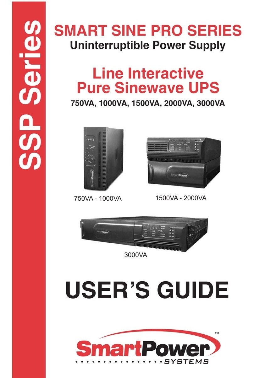
Smart power Smart Sine Pro Series User manual
Smart power
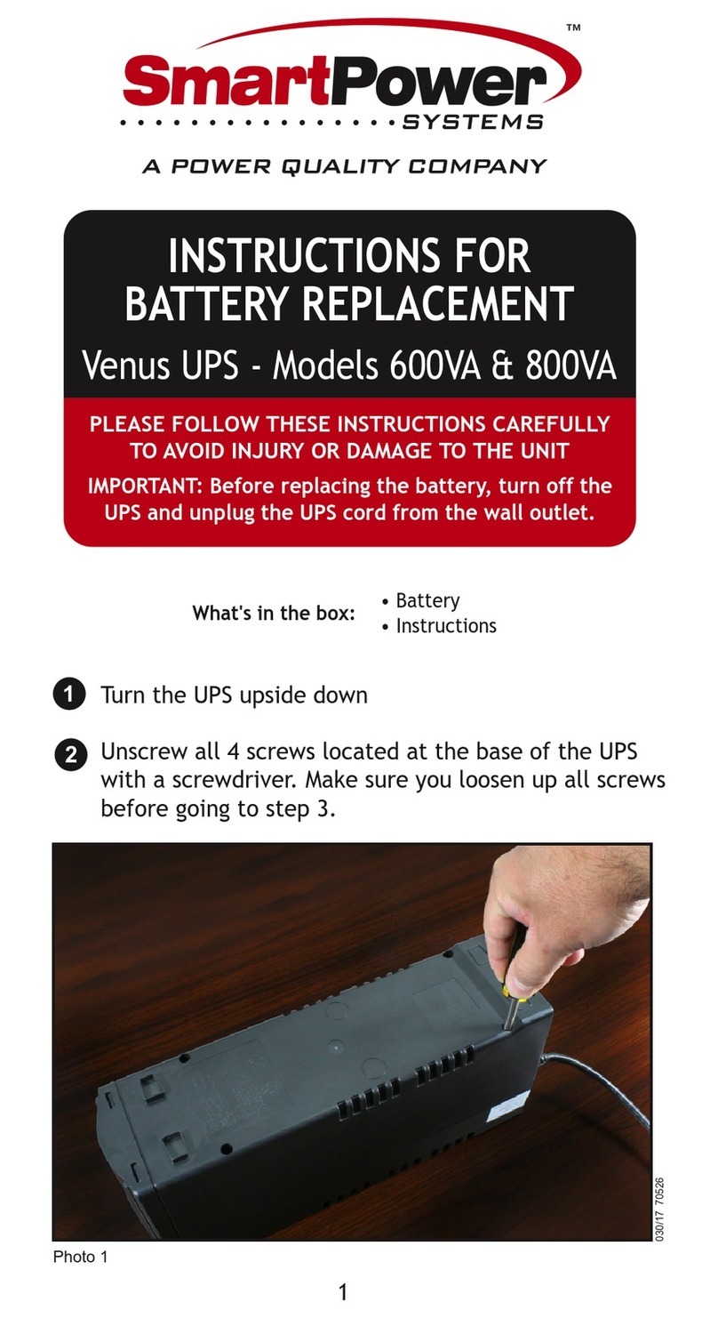
Smart power Venus Series User manual
