Forward FN455 User manual
Forward FN455
Manual

Content
Description
Package Contents
Specifications
Features
Components and Controls
Button Operation
Using the Battery Pack
Battery Charging
Battery Installation
Safety Measures
External Power Supply
Operation
Operating Features
Installing Digital Module on the Optical Device
Installing Pulsar 5x30 Monocular on to the Digital Module
Powering on and Image Setting
IR Illuminator
Installing the IR Illuminator
Removing the IR Illuminator
Status Bar
Quick Menu Functions
Main Menu Functions
Enter the Main Menu
Icon Brightness
Microphone
Wi-Fi Settings
General Settings
Auto Shutdown
Device Information
Bluetooth
Video Recording and Photography
Wi-Fi Function
Display Off Function
SumLight™ Function
Wireless Remote Control
Descriptions of Controls
Remote Control Activation
Using the Weaver Rail
Stream Vision 2
Firmware Update
USB Connection


Description
The Forward FN455 digital night vision device is designed for various areas of application,
including hunting surveillance, security activities, night photography and video recording.
The digital module included in the Forward FN455 package can be mounted on lenses of
various daytime optical instruments using special adapters, enabling them to be used for night-
time observation.

Package Contents
Digital module
Pulsar 5x30 Monocular
Carrying Case
IPS7 Battery Pack
Battery Pack Charger
Power Adapter
USB Cable
Quick Start Guide
Lens-Cleaning Cloth
Warranty Card

Specifications
FN455
Model FN455
SKU 78196
Optical Characteristics
Lens focus, mm 50
Relative aperture, D/f 1:1
Field-of-view (Horizontal), ° 6.3
Field-of-view (Horizontal), m per 100 m 11
Detection Range (animal height 1.7 m),
m/y 500/546.8
Minimum Focusing Distance, m/y 5
Recommended daylight optics
magnification, x 2-8
Electronic Specifications
Sensor type / resolution CMOS HD 1280X720
Display type / resolution AMOLED 1746x1000
Detachable IR Illuminator
Type / wavelength, nm LED 940
Operational Characteristics
Power Supply, V 3.1-4.2
Battery type / Capacity / Rated Output
Voltage Li-Ion Battery Pack IPS7 / 6400 mAh /
DC 3.7 V
External Power Supply Micro USB type B (5V)
Max. Battery Pack Life at t = 22 °C (Wi-
Fi off, IR off), Hour 9
Degree of protection IP code
(IEC60529) IPX7
Operating temperature, °C -25 - +50
Overall Dimensions (with battery and
monocular),
mm/inch 273?136?77 / 10.75x5.35x3.03

Weight (with battery and monocular),
kg/oz 1.03 / 35.27
Video Recorder
Video/Photo Format .mp4 / .jpg
Built-in Memory 16 GB
Wi-Fi Channel*
Frequency 2.4 GHz
Standard 802.11 b/g
*Reception range may vary depending on various factors: the presence of obstacles, other Wi-
Fi networks.


Features
1280X720 HD sensor
Enhanced night-time sensitivity
Simple transformation of a daytime optical device into night device.
Preserves the benefits of daytime optics in night-time conditions
Comfortable use in a wide range of daytime optical magnifications
Invisible long-range IR Illuminator
SumLight™ enhanced sensitivity firmware
Detection distance of up to 500m
Instant power up
Built-in video
Power from quick-release, high-capacity B-pack rechargeable batteries
Four-point mounting system with automatic clamp
Wireless remote control
Wi-Fi integration with iOS and Android devices
Stream Vision. Remote control surveillance and live YouTube streaming via smartphone
Remote firmware updates
Fully waterproof (IPX7)
Extreme operating temperature range (-25 °C – +50 °C / -13 °F – +122 °F)
MicroUSB Power Bank charging
Storing photos and videos in Cloud when using the Stream Vision 2 App
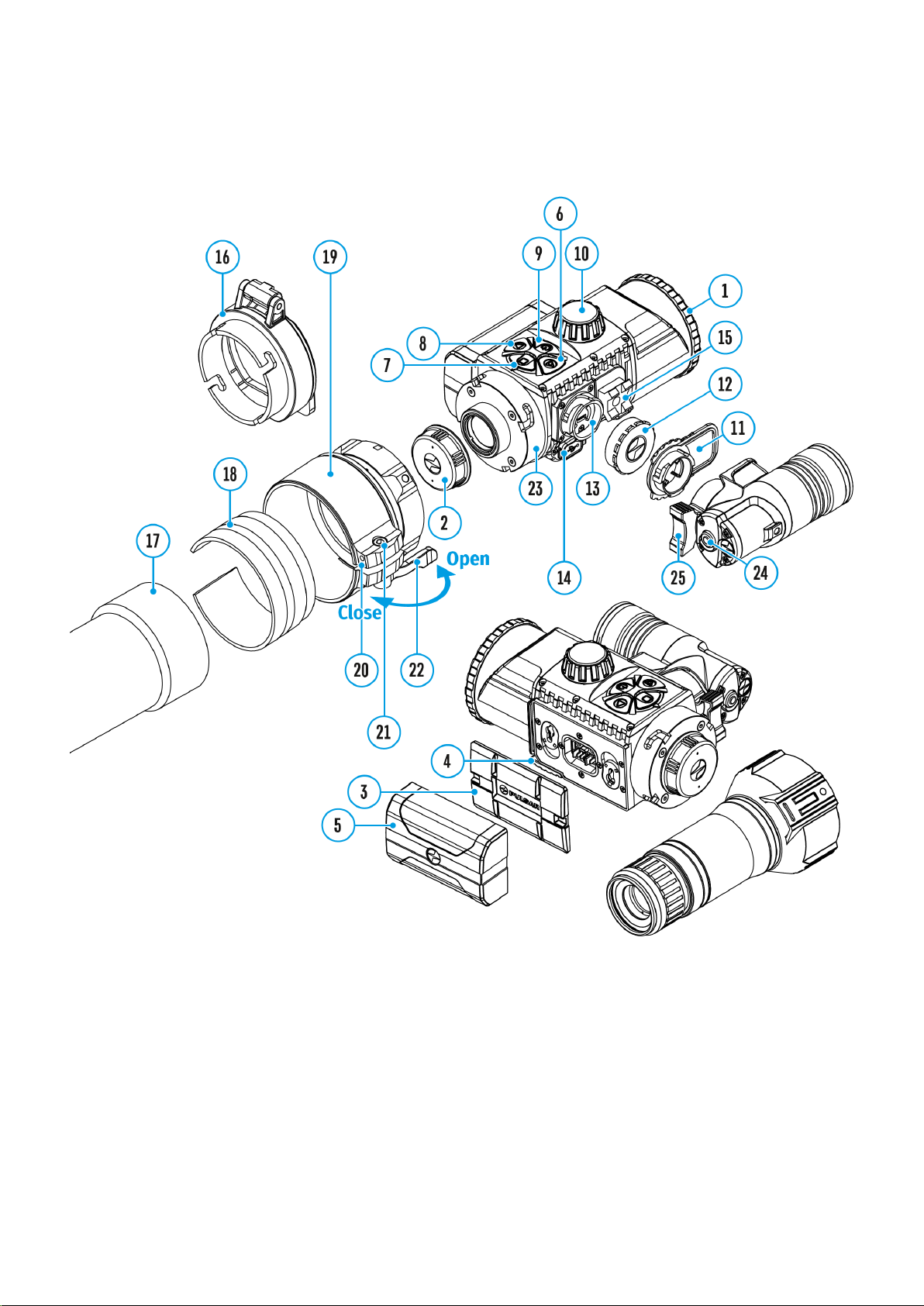
Components and Controls
1. Lens cover
2. Eyepiece cover
3. Battery compartment cover
4. Battery locking lever
5. Battery pack
6. RIGHT button
7. M (MENU) button
8. LEFT button
9. ON/OFF button
10. Lens focus knob

11. IR illuminator cover
12. IR illuminator connector cap
13. Connector for installing IR illuminator
14. MicroUSB port
15. Weaver rail
16. Adapter cover*
17. Optical device lens
18. Insert*
19. Adapter*
20. Tightening screw*
21. Screw*
22. Adapter lever*
23. Mounting area
24. IR button
25. IR illuminator arm
*Items of Cover Ring Adapter FN (available separately)
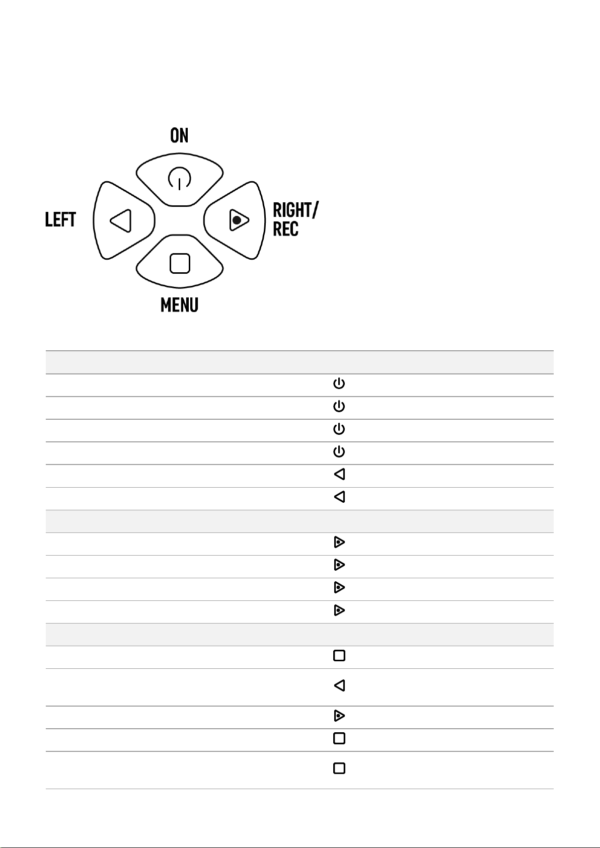
Button Operation
Operation Button
Power device on short press
Power device o? long press for 3 secs
Turn display o? long press for less than 3 secs
Turn display on short press
Turn on/off SumLight™ short press
Turn on/off Wi-Fi long press
VideoRecorder Button
Start/pause/resume video recording short press
Stop video recording long press
Switch to video/photo mode long press
Capture Photo short press
Main Menu Button
Enter main menu long press
Navigation
downwards/counterclockwise short press
Navigation upwards/clockwise short press
Confirm value short press
Exit submenu without confirming
selection long press

Exit main menu long press
Quick Menu Button
Enter quick menu short press
Switch between quick menu options short press
Increase value short press
Reduce value short press
Exit quick menu long press
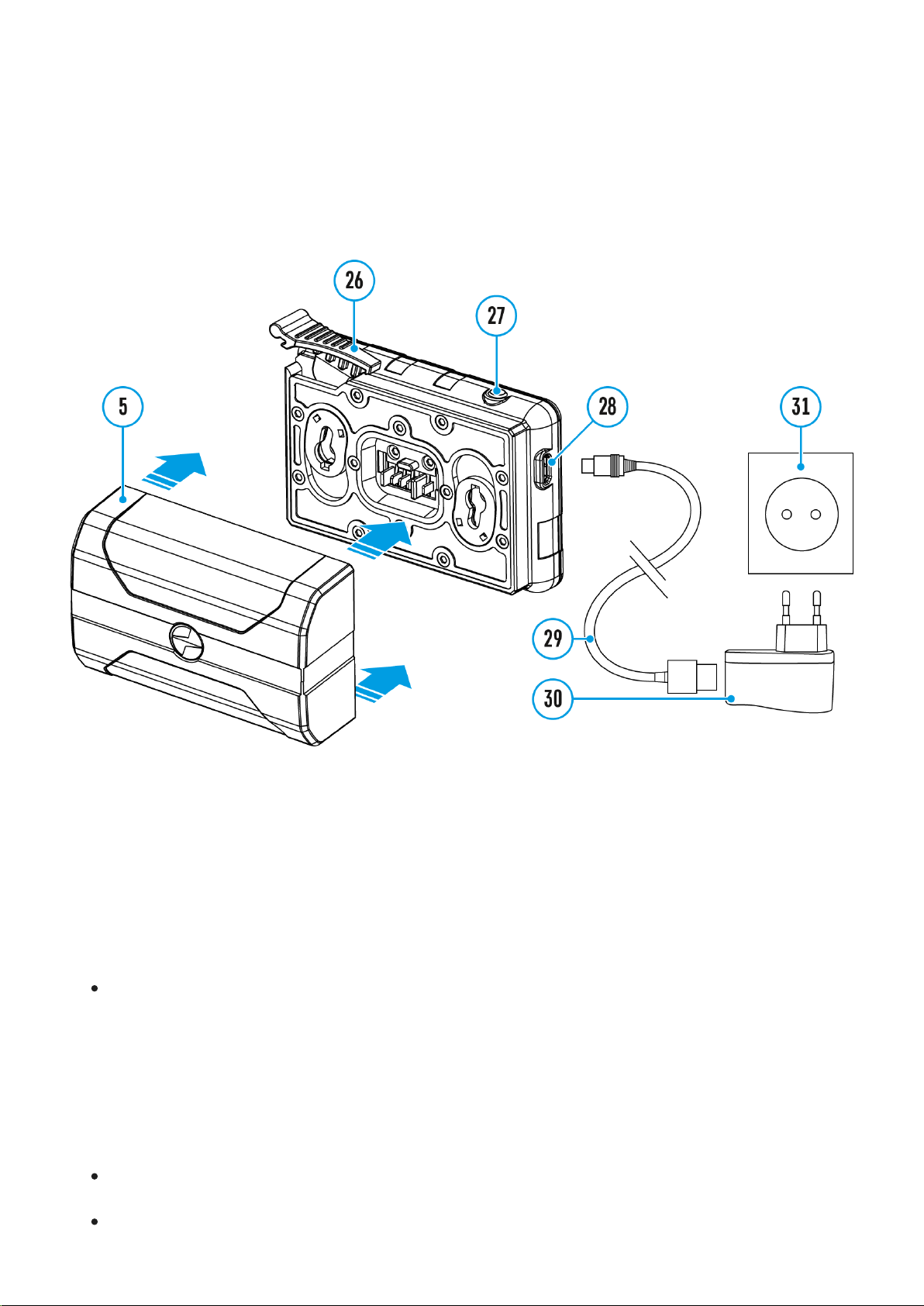
Battery Charging
The device is supplied with a rechargeable IPS7 Lithium-ion Battery Pack which allows the
attachment to be used for up to 9 hours. Charge the battery before first use.
Charging
Step 1. Install the battery into the charger
1. Raise the lever(26) of the charger.
2. Install the Battery Pack (5) into the charger.
3. Click the lever (26).
Step 2. ?heck the current battery level
Upon installation, a green LED indicator (27) on the charger will start to glow and begin
flashing:
- once if the battery charge ranges from 0% to 50%.
- twice if the battery charge ranges from 51% to 75%.
- three times if the battery charge ranges from 76% to 100%.
When the indicator is continuously green, the battery is fully charged. Disconnect the
charger from the mains and disconnect the battery from the charger.
If the battery charger indicator is constantly red when the battery is inserted, the charge

level is probably below the permissible level (the battery has been in a discharged state
for a long period of time). Leave the battery in the charger for a long period of time (up to
several hours), then remove and reinsert.
If the indicator begins to flash green, the battery is good.
If it continues to show red, the battery is defective. Do not use this battery!
The LED indicator (27) will display the battery charge status:
LED Indicator (27) Battery Charge Status
Battery is empty
Image not found or type unknown Battery is full
Step 3. ?onnect the charger to the mains supply
1. Attach the microUSB plug of the USB cable (29) to the microUSB connector (28) on the
charger.
2. Connect the USB plug on the cable(29) to the power adapter (30).
3. Plug the power adapter(30) into a 100-240V (31) socket.
4. When the indicator (27) is continuously green, the battery is fully charged. Disconnect
the charger from the mains.
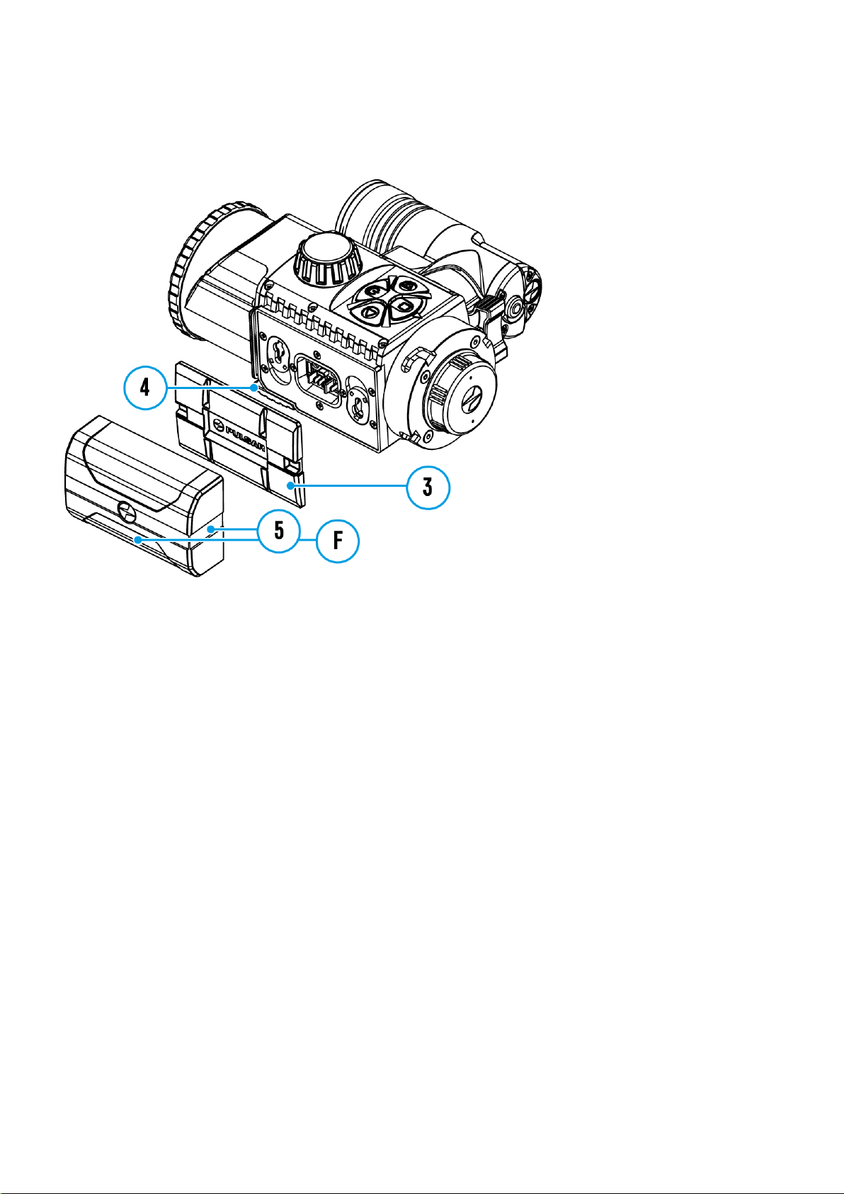
Battery Installation
1. Lower the lever (4).
2. Remove the protective cover of the battery compartment (3).
3. Insert the battery(5) into the slot designed for it on the device body so that the element
(F) is pointing downwards.
4. Lock the battery in place by raising the lever (4).

Safety Measures
Do not use the charger if it has been modified or damaged.
Do not leave a battery unattended during charging.
Do not leave the battery in a charger connected to the mains after charging is complete.
The battery should be charged at a temperature between 0° C and +45° C, otherwise the
battery life will be significantly reduced.
Do not charge the battery immediately after bringing it from the cold into a warm
atmosphere. Wait 30–40 minutes for the battery to warm up.
Do not expose the battery to high temperatures or naked flame.
Do not submerge the battery in water.
The connecting of third-party devices with an energy consumption greater than
permissible is not recommended.
The battery is equipped with a short circuit protection system. However, situations that
may lead to short circuiting should be avoided.
Do not dismantle or deform the Battery Pack.
Do not subject the Battery Pack to shocks or falls.
When using the battery at negative temperatures, battery's capacity decreases, this is
normal and is not a defect.
The batteries should be partially charged (50 to 80 %) for long-term storage.
Store the battery out of the reach of children.

External Power Supply
External power is supplied from an external source, such as a 5V Power Bank.
1. Attach the external power source to the USB connector(14) on the device.
2. The device will switch to operation from the external power supply, while the IPS7
battery will be gradually recharged.
3. A battery icon will appear on the display showing charge level as a percentage.
4. If the device is connected to a computer, network adapter or power bank that does not
conform to the BC1.0 battery charger standard, an IPS7 battery will not begin charging:
the external power icon only will be displayed .
5. If the device is operated from an external power source and the IPS7 battery is not
connected, an icon is displayed .
6. Once the external power source is disconnected, the adapter will begin functioning on
battery power.
Attention! Charging Power Bank IPS7 batteries at air temperatures below 0 °C can result in
reduced battery life. When using external power, connect Power Bank to the switched-on
device, which have worked for several minutes.
To see the Components and Controls scheme click here.

Operating Features
The Forward FN455 device is designed for long-term use. Please follow these guidelines to
ensure long life and maximum performance:
Before using the attachment make sure you mount it according to the instructions in the
Installing Digital Module on the Optical Device and Installing Pulsar 5x30 Monocular
on to the Digital Module sections.
Power off the device after use.
Do not repair or dismantle an attachment under guarantee by yourself!
The device can be used over a wide range of temperatures. If the device has been
operated in the cold and brought into a warm room, do not remove it from its carrying
case for at least 2-3 hours; this will prevent condensation forming on the external optical
elements.
Inspect and maintain the device regularly to ensure trouble-free operation and to avert
and eliminate the cases of premature wear and tear and failure of components.

Installing Digital Module on the
Optical Device
1. Select the adapter (available separately) with the required diameter of insert depending on
the outer diameter of the lens of your optical device (see the Table).
2. The designation 42mm / 50mm / 56mm in the title of the adapter refers to the optical
diameter of the lens in the optical device.
3. Remove the cap(16) from the 42mm adapter (19) (SKU 79171) by turning it clockwise. To
remove the cap from the 50mm (SKU 79172) or 56mm (SKU 79173) adapters, turn it
anticlockwise.
4. Degreasing of the body of the optical device before mounting is recommended.
5. Mount the insert (18) onto the adapter(19) as far as it will go.
This manual suits for next models
1
Table of contents
Other Forward Monocular manuals


