Forza Fusion Series User manual

1KW/2KW/3KW
User Manual
2-year
warranty*
Off-grid hybrid solar inverter and charger
FIO-F11K12P / FIO-F12K24P / FIO-F13K48P

Table of content
IMPORTANT SAFETY INSTRUCTIONS
1. Introduction
2. Product overview
3. Preliminary steps
4. HARDWARE CONNECTIONS
4.1 AC connections
4.2 PV
4.3 Other communications
5. Operation
5.1 Power on/off
5.2 Display panel
6. Advanced operation
6.1 Main LCD configuration screen
6.2 Display information
6.3. Battery charging
6.3.1 Battery equalization
7. Parallel operation
7.1 Parallel board installation
7.2 Wiring considerations
7.3 Parallel connections on a single-phase system
7.4 Parallel connections on a three-phase system
8. Advanced LCD configuration screen
9. Commissioning and maintenance
10. Fault codes and warning indicators
11. Troubleshooting
12. Approximate runtime chart
13. Technical specifications

1
IMPORTANT SAFETY INSTRUCTIONS
This manual contains important information regarding the operation and warranty of the Forza Inverter Series. As with
any electrical equipment, certain precautions must be observed when installing the unit. To reduce the risk of personal
injury and to ensure safe installation and operation, carefully read and follow all instructions, cautions and warnings
included in this manual. Keep it in a safe place for future reference.
1. Before using the unit, read all instructions and cautionary markings on the unit, the batteries and all appropriate
sections of this manual.
2. CAUTION --Charge only deep-cycle lead acid rechargeable batteries. Other types of batteries may burst, causing
personal injury and damage.
3. Do not disassemble this product. If service or repair are required, consult a qualified service center.
4. Incorrect re-assembly may cause electric shock or fire.
5. To reduce the risk of electric shock, disconnect all wiring before attempting any maintenance or cleaning. Turning
off the unit will not reduce this risk.
6. CAUTION – Installation of the batteries should be performed only by qualified personnel.
7. NEVER charge a frozen battery.
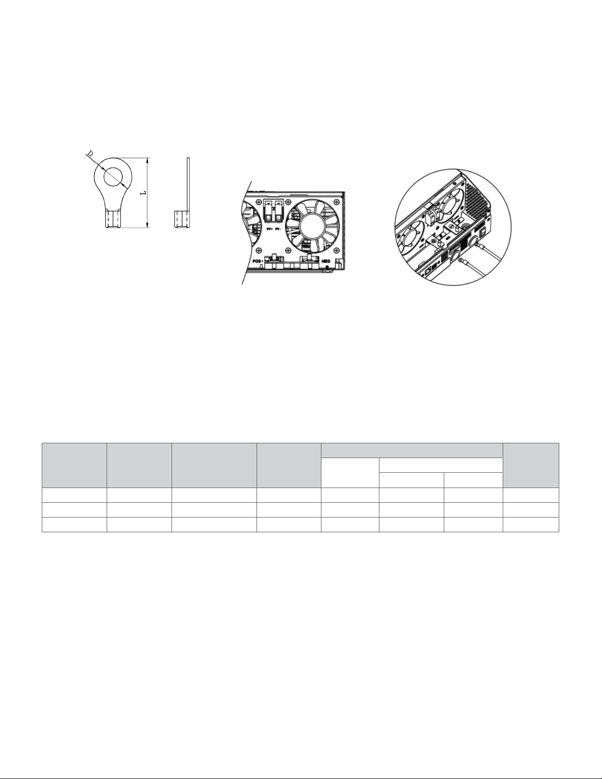
8. For optimum performance of this inverter/charger, follow all wire and cable sizing specifications included in the
manual.
9. Avoid dropping tools onto batteries or other electrical parts.
10. Always use insulated tools.
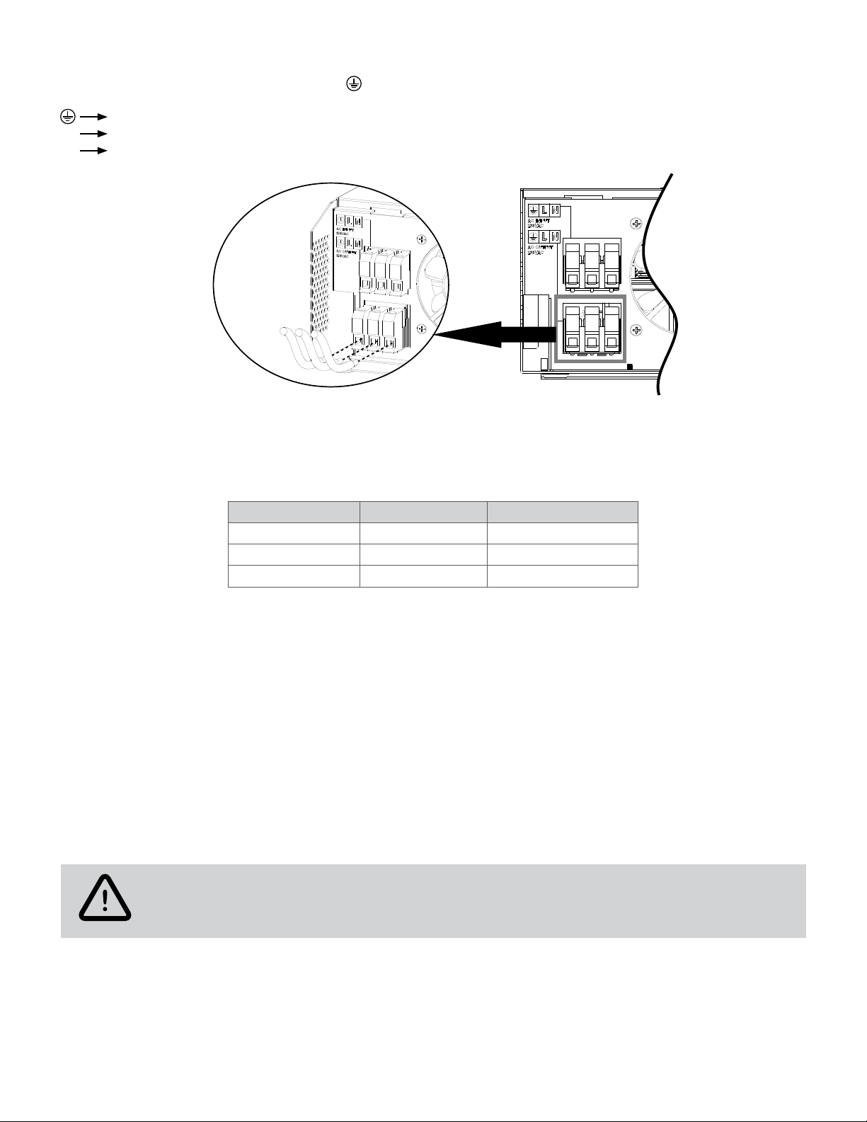
11. This product must be connected to a permanent grounded wiring system.
12. All wiring and installation methods must comply with local codes and regulations.
13. Do not reverse the polarity of the battery cables. This will destroy the product.
14. Ensure that neither the AC nor the DC circuit is allowed to be short-circuited. Do not connect the system to any AC
source if a short circuit occurs.
1. Introduction
Thank you for purchasing the FUSION Off-grid solar inverter from Forza.
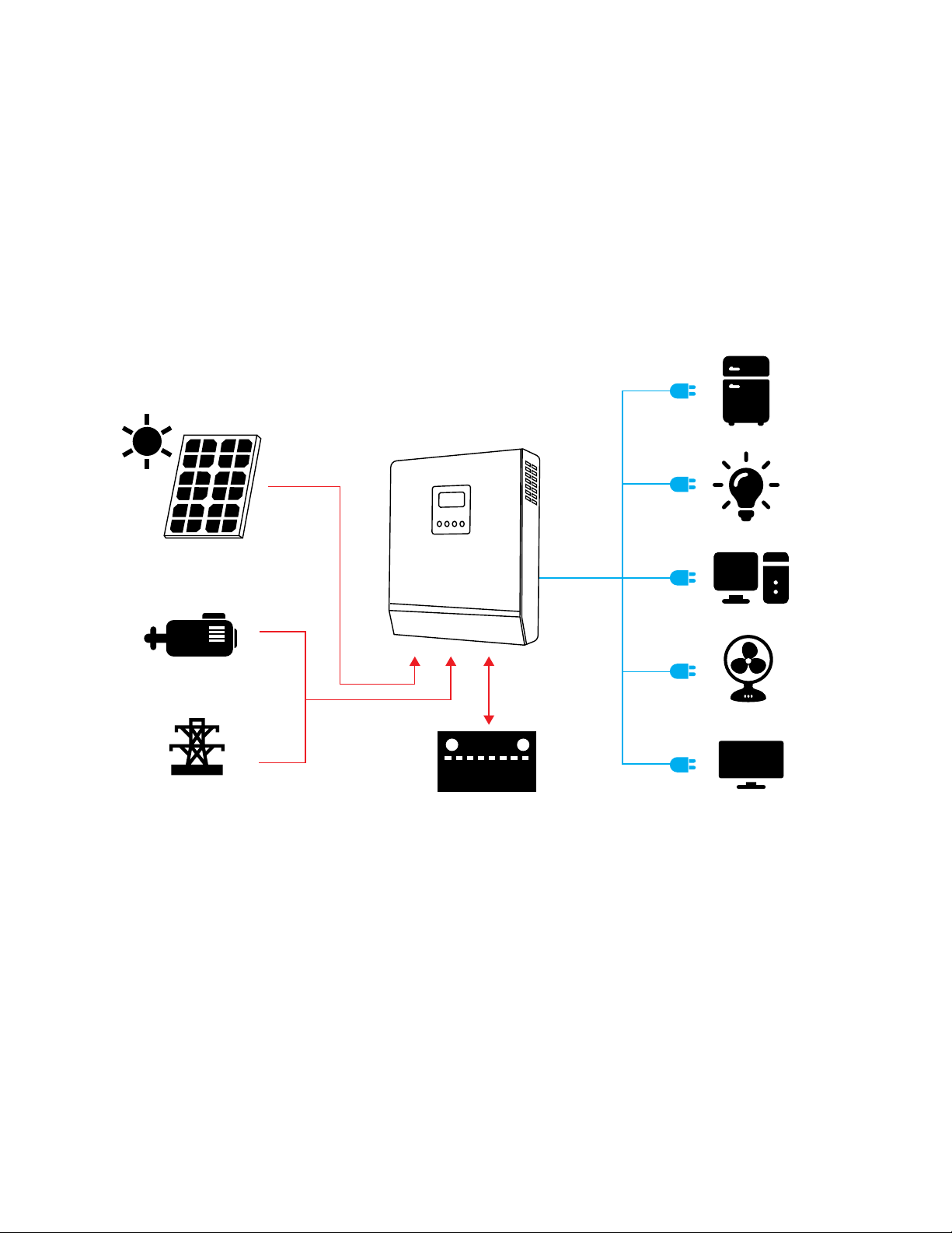
Our FUSION line is made up of inverters designed for off-grid, single-phase photovoltaic applications. Equipped with
an MPPT charger, the FUSION optimizes energy harvesting while reducing system maintenance and operational costs.
As the inverter has been conceived to easily integrate with the Forza battery and the embedded application, it provides
seamless status monitoring along with remote management, all in real-time. It also features parallel operation with up
to 9 identical units when used in conjunction with the optional parallel kit.
Available in the 120-volt version, and with capacities of 1000W, 2000W and 3000W respectively, the FUSION is
characterized for its sturdy construction, outstanding performance and industry-grade design life.
Features
• Zero (0ms) transfer time to protect mission-critical loads
• Pure sinewave solar inverter
• Highly efficient MPPT (Maximum Power Point Tracking) charge controller
• Output power factor of 1
• Features restart functionality, including the “cold start” option from battery
• Wide DC input range
• Selectable input voltage range for home appliances and personal computers
• Configurable AC/Solar input priority via LCD
• Marine/offshore and generator applications
• Smart battery charger design for optimized battery performance
• Rugged design with overload, overtemperature, and short-circuit protection
• Parallel operation with up to 9 units (requires parallel kit)
• Three-phase compatible in parallel operation (requires parallel kit)

2
Basic system architecture
The following diagram illustrates a basic application for this inverter/charger. A complete running system should include
the following power sources:
- Generator or utility
- PV modules
Consult with your system integrator for other possible system architectures depending on your requirements.
This inverter can power a wide assortment of appliances in home or office environments, including motor-type appliances
such as fans, refrigerators, air conditioners and even tube lights.
Off-Grid Hybrid Power System
Solar Power
(option)
External
battery packs Home appliances
Generator
OR
Utility
BATTERY

3
1. LCD display panel
2. Status LED indicator
3. Charging LED indicator
4. Fault LED indicator
5. Configuration buttons
6. Power on/off switch
7. Grid connection (input)
8. AC output (load connection)
9. PV connector
10. Battery input
11. Circuit breaker
12. Parallel communication ports
13. Current sharing ports
14. Dry contact terminals/Auxiliary dry contacts
15. RS-232 communication port
16. USB communication port
3. Preliminary steps
Unpacking and inspection
Upon opening the box, make sure the following items are included:
• Inverter unit (1)
• USB communication cable (1)
• RS232 communication cable (1)
• Software CD (1)
• Mounting screw kit (1)
• User manual (1)
Carefully inspect the unit before installation. Make sure that nothing inside the package is damaged or loose. Keep the
original package in a safe place for future use.
2. Product overview

4
Preparation
1. On the underside of the unit, unfasten the screws holding the cover in place.
2. Remove the bottom cover to expose the wired connections and ports.
Leave the screws in a safe place for replacing the cover once the hardware connections are completed.
Mounting the unit
Important
• Mount the unit on concrete or another non-combustible surface only.
• Install the unit at eye level for easy reading of the display panel.
• This product will function most effectively if installed upright.
• For optimal operation, ambient temperature should be between 0°C and 55°C.
• Observe all marked clearance requirements when a single or multiple units are installed.
Mounting and clearances

5
For proper ventilation and heat dissipation, allow clearances of approximately 8in (20cm) to either side
and 20in (50cm) above and below the unit. When more than one unit is installed, make sure to position
them at the same level.
WARNING: Shock hazard
All wiring must be performed by qualified personnel. High voltages can be harmful to human life.
4. HARDWARE CONNECTIONS
Battery:
1. First assemble the batteries in series or parallel as needed for the system nominal voltage.
2. Install all cables and interconnections.
NOTES:
• Cables and ring terminals should be sized according to the table below.
• For safety and compliance purposes, install a DC overcurrent protection between this unit and the battery. This is
required for both safety reasons and regulatory compliance. A manual disconnect device may also be required.
These devices should be sized according to the cable size (see table).
• The minimum recommended battery capacity for this model is 100Ah.
• To secure the unit(s) in place, insert the supplied M5x12mm hex screws at points A, Band C. M4 screws can be used
as well.
A
B
C

6
Ring terminal:
3. Insert the positive (+) and negative (–) ring terminals on the studs of the inverter observing the correct polarity at both
ends.
4. Tighten all connections according to the torque values listed in the table. It also contains the amperage values, plus
the recommended size of cables and terminals.
Battery conductors
CAUTION: Hazard to equipment
- Do not reverse the polarity of the positive (+) and negative (–) battery cables. Otherwise, the product will be damaged.
Check the polarity of all connections before applying power to the battery.
- Do not place any other object or hardware between the inverter terminal surface and the ring terminal. Overheating
may result.
- Apply antioxidant compound to protect the terminals.
Model Maximum
current
Recommended
battery capacity Cable size
Ring terminal Terminal
torque
Cable
mm²
Dimension
Diameter Length
1KW 140A 200Ah 1x4AWG 28 6.4mm 49.7mm 2~ 3 Nm
2KW 140A 200Ah 1x4AWG 28 6.4mm 49.7mm 2~ 3 Nm
3KW 140A 200Ah 1x4AWG 28 6.4mm 49.7mm 2~ 3 Nm

7
4.1 AC connections
Before any connections are made, open all disconnect devices on both AC and DC sources.
To install AC input and output connections for the inverter:
1. Remove 0.4in (10mm) of the insulation sleeve from each of the six conductor wires. Trim an additional 0.11in (3mm)
of conductor wire from phase L (line) and N (neutral).
2. Insert AC input wires observing the polarity marked on the terminal block, then proceed to tighten the screws. The
protective earth (PE) conductor ( ) must be connected first.
Ground (yellow-green)
L LINE (brown or black)
N Neutral (blue)
CAUTION!! Before connecting to AC input power, install a separate circuit breaker between the inverter
and AC source. It is needed for AC input overcurrent protection and also as a manual disconnect
device during maintenance. The recommended specification for the AC breaker is 16A for 1KVA, 32A
for 2KVA and 48A for 3KVA.
CAUTION!! Two terminal blocks with IN and OUT markings are provided. Be careful not to reverse the
connections to the input and output terminals. Check all connections before applying power.
WARNING: Shock hazard
All wiring must be performed only by a qualified electrician. High voltages can be harmful to human life.
WARNING! For system safety and efficient operation, use the appropriate cable to make AC input
connections. To reduce the risk of injury, the recommended wire size shown in the table below should
be followed.
WARNING:
Be sure that AC power source is disconnected before attempting to hardwire it to the unit.

8
3. After inserting the AC output wires observing the polarity marked on the terminal block, proceed to tighten the
screws. The protective earth (PE) conductor ( ) must be connected first.
Ground (yellow-green)
L LINE (brown or black)
N Neutral (blue)
4. Verify that that all wire connections are properly secured.
Recommended AC conductor size
When selecting PV modules, observe the following parameters:
• Never exceed the maximum permitted open-circuit voltage (VOC), specified for the PV array.
•The open-circuit voltage (VOC) of PV modules should be higher than the minimum specified for the battery.
CAUTION:
Follow the correct polarity when connecting AC wires. If Land Nwires are reversed, it may cause a utility short-circuit
when the inverters are in parallel operation.
NOTE: Appliances such as air conditioners often require at least 3 minutes to restart after a short-term power outage
(time is required to balance the refrigerant gas in inside circuits). In order to protect your air conditioner, consult the
manufacturer whether they have already provided a time delay function before the installation. Otherwise, the inverter
will trigger an overload fault and shut off its output to protect your appliance. Even so there is some risk of damage to
the air conditioner.
Model Gauge Terminal torque
1KW 16 AWG 1.4~ 1.6Nm
2KW 12 AWG 1.4~ 1.6Nm
3KW 10 AWG 1.4~ 1.6Nm
4.2 PV
Selection of the modules
CAUTION: Hazard to equipment
Never exceed the maximum Voc. under any circumstances. This can cause permanent
damage to the unit.

9
To connect the PV modules to the unit:
1. Remove approximately 0.4in (10mm) of the insulation from the PV wires.
2. Identify the cable coming from the PV modules and the PV input connectors located on the inverter.
3. Following the correct polarity, insert the positive (+) wire into the positive terminal of the PV input, and the negative
(–) wire into the negative terminal of the PV input. Refer to the image below.
4. Tighten all connections to the torque values, as shown on the table above in this section.
Table– Module voltages
Model Gauge Torque
1KW 10 AWG 1.2~1.6 Nm
2KW 8 AWG 1.2~1.6 Nm
3KW 6 AWG 1.2~1.6 Nm
Solar charging mode
INVERTER MODEL 1KW 2KW 3KW
Max. PV array open-circuit voltage 145VDC
PV array MPPT voltage range 15~115VDC 30~115VDC 60~115VDC
Min. battery voltage for PV charge 8.5VDC 17VDC 34VDC
Connection of the modules
NOTES:
• PV wires should be sized according to the table below.
• A separate DC circuit breaker should be installed for overcurrent protection. It must be placed between the inverter
and the PV modules.

10
Final assembly
1. Place the bottom cover near the inverter housing.
2. Install the supplied communication cables in the corresponding ports.
3. Set the bottom cover in place. Then, secure it using the same screws that were removed in the previous steps.
4.3 Other communications
The inverter supports several forms of communication.
A. USB
Port used for connection with a PC.
Insert the supplied CD into the computer and follow the on-screen instructions to install the monitoring software. For the
detailed software operation, refer to the digital user manual from the download section of the product website.
B. Serial (RS-232)
Port used to allow communication between the inverter and a PC. Insert the supplied CD into the computer and follow
the on-screen instructions to install the monitoring software. For the detailed software operation, please check the
digital user manual from the download section of the product website.
C. Auxiliary contacts
There is a set of dry contacts (3 amperes, 250 VAC) on the rear panel, which are controlled by battery and charging
voltage. These terminals can serve as a switch for auxiliary devices to indicate low voltage and other situations.

11
5. OPERATION
5.1. Power on/off
Once the inverter/charger has been properly installed and the batteries set as its power source, simply press the on/off
switch (located at the bottom) to turn on the unit.
Unit status Condition
Dry contact terminals:
Normally closed (NC) Common (C)
Normally open (NO)
State
NC and C NO and C
Power off The inverter is off, and no power is supplied to the output Close Open
Power on
The output is being powered from an AC source Close Open
The output
is powered
from either
battery or PV
energy
Item 01 set
as Utility
Battery voltage < low DC warning
voltage Open Close
Battery voltage > Setting value in
item 13 or battery charging has
reached float stage
Open Close
Item 01 is set
as SBU (solar
priority)
Battery voltage < Setting value in
item 12 Open Close
Battery voltage > Setting value in
item 13 or battery charging has
reached float stage
Open Close

12
5.2. Display panel
Located on the front of the unit, this panel features a LCD screen, LED indicators and configuration buttons.
LED indicators
The display panel features three LED indicators.
Configuration buttons
The display panel features four buttons for setting up the inverter parameters.
LCD display
LED indicators
Configuration buttons
Description Status
Green Solid Loads are powered by an AC source in Line mode
Intermittent Loads are powered by battery or in PV mode
Green Solid Battery is fully charged
Intermittent Battery is charging
Red Solid Inverter error (fault)
Intermittent Inverter warning
Description Command
ESC To exit the current setting
UP To move up to the previous selection
DOWN To move down to next selection
ENTER To confirm or select a parameter. It is also used to access the configuration mode

13
LCD display icons
The display contains a variety of icons showing the status and operation mode of the inverter.
Icon Function description
Input source information
Indicates that an AC input is connected
Indicates that PV input is connected
Indicates AC input voltage and frequency, PV voltage, charging current and battery
voltage
Settings, warning and fault indications
Displays the setting screen mode
Shows any warning or fault codes.
A warning code appears intermittently, followed by an .
A fault code lights up showing the detected event or condition
Output data
Indicates AC output voltage and frequency, load percentage, load in volt-amps and
watts, and discharge current
kW
VA
%
Hz
OUTPUTBATTLOAD

14
Battery data
Battery level indicator at 0-24%, 25-49%, 50-74%, and 75-100% of its capacity
In battery mode, the number of bars shows the remaining charge
In line mode, the number of bars indicates how much charge it will need to reach its full
capacity
In AC mode, the battery state of charge is displayed
Status Battery voltage LCD Display
Constant Current
mode / Constant
Voltage mode
<2V/cell 4 bars will flash alternatively
Bottom bar will be on and the other
three bars will flash alternatively
2.083 ~ 2.167V/cell Bottom two bars will be on and the other
two bars will flash alternatively
> 2.167 V/cell Bottom three bars will be on and the top
bar will flash
Float stage: maintains batteries in a fully
charged state 4 bars will be on
In battery mode, the remaining capacity is displayed
Load percentage Battery voltage LCD Display
Load >50%
< 1.717V/cell
1.717V/cell ~ 1.8V/cell
1.8 ~ 1.883V/cell
> 1.883 V/cell
50%> Load >
20%
< 1.817V/cell
1.817V/cell ~ 1.9V/cell
1.9 ~ 1.983V/cell
> 1.983
Load < 20%
< 1.867V/cell
1.867V/cell ~ 1.95V/cell
1.95 ~ 2.033V/cell
> 2.033
Load information
Displays the inverter shutdown due to an overload
Indicates the load level compared to the inverter’s maximum load capacity in
increments of 0-24%, 25-49%, 50-74% and 75-100%
0%~24% 25%~49% 50%~74% 75%~100%

15
Mode of operation
Indicates that the unit is connected to an AC source
Indicates that the unit is connected to a PV panel
Indicates that the inverter is operating in bypass mode
Indicates that the inverter is operating in ECO mode
Indicates that the AC source is charging the battery
Indicates that the DC-AC conversion is enabled
Mute control
Indicates that the audible alarm is disabled
Item Description Selectable parameters
00 Exit the setting screen
mode
Escape
01
Output source priority
setting:
If multiple power sources
are available, this controls
which source is used first
to power the loads
USB: Utility first (default) Utility will provide power to the loads
as first priority.
Solar and battery energy will provide
power to the loads only when AC
source is not available
SUB: Solar first Solar energy provides power to the
loads as first priority.
If solar energy is not enough to power
all the connected loads, the AC
source will assist PV.
Batteries will be used if neither PV nor
AC is available or insufficient.
SBU priority Solar energy provides power to the
loads as first priority.
If solar energy is not enough to power
all the connected loads, battery
power will assist PV.
AC source is only used if the battery
drops to the low battery warning level
or when it reaches the AC transfer
voltage setting in item 12.
6. Advanced operation
6.1. Main LCD configuration screen
To enable the configuration screen mode, press and hold the ENTER button for 3 seconds. Use the UP or DOWN
buttons to go through the available parameters within each menu item. Pressing the ENTER button again allows the
selected item to be set. To exit, simply press the ESC button.

16
02
The total input generated
by solar and AC sources
combined
(Max. charging current =
utility charging current +
solar charging current)
60A (default) This setting ranges from 10A to 140A
with increments of 10A per click 60A
is the default value
05 Battery type
AGM (default)
Flood
User-defined If user defined is selected, then
battery charging and low DC cutoff
voltages can be programmed in items
26, 27 and 29
06 Auto-restart when an
overload shutdown occurs
Restart disable (default) Restart enable
07
Auto-restart when an over-
temperature shutdown
occurs
Restart disable (default) Restart enable
09 Output frequency
50Hz 60Hz (default)
10 Mode selection
Automatic (default) If selected having utility power
available, the inverter will operate
in line mode. If the AC frequency
becomes unstable, the inverter will
transfer to bypass mode provided this
function is not forbidden in item 23
Online mode If selected, the inverter will operate in
line mode when AC input is available
ECO mode If selected and bypass is not
forbidden in item 23, then the inverter
will operate in ECO mode when utility
is available
11 Maximum charge current
(from the AC source)
2A 10A
20A 30A (default)
40A 50A

17
60A
12
Defines the AC transfer
voltage when the priority
source in item 01 is set to
SBU or SUB
Available options in the 1KW model
11.0V 11.3V
11.5V (default) 11.3V
12.0V 12.3V
12.5V 12.8V
13.0V 13.3V
13.5V 13.8V
14.0V 14.3V
For the 2KW model, the setting ranges from 22.0V to 28.50V in
increments of 0.5V per click. The default setting is 23.0V.
For the 3KW model, the setting ranges from 44.0V to 57.0V in
increments of 1.0V per click. The default setting is 46.0V

18
13
Defines the battery transfer
voltage when the priority
source has been set to
SBU or SOL in item 01
Available options in the 1KW model
Fully-charged battery 12.0V
12.3V 12.5V
12.8V 13.0V
13.3V 13.5V (default)
13.8V 14.0V
14.3V 14.5V
14.8V 15.0V
15.3V 15.5V
15.8V 16.0V
For the 2KW model, the setting ranges from 24.0V to 32.0V in
increments of 0.5V per click. The default setting is 27.0V.
Battery fully charged Default setting: 27.0V
For the 3KW model, the setting ranges from 48.0V to 64.0V in
increments of 1.0V per click. The default setting is 54.0V.
Battery fully charged Default setting: 54.0V
This manual suits for next models
3
Table of contents