FORZATEK X3 Series User manual

BATTERY CHARGERS - Series X3(3N) and X5 (5N)
Use and maintenance manual
anuel d'utilisation et d'entretien
rev. 10/18

1
Serie 3
N
/5
N
– Use and maintenance manual rev 10/18
1 WARNINGS - SAFETY ................................................................................................................................. 2
1.1 S
AFETY AND
R
EFERENCE
R
ULES
........................................................................................................................ 3
1.2 T
HERMAL SECURITY DEVICES AND SYSTEM
............................................................................................................ 3
1.3 E
LECTRICAL INFORMATION
.............................................................................................................................. 3
2 SERIES AND ODEL RANGES ..................................................................................................................... 4
2.1 S
ERIE
–
3N
AND
5N ..................................................................................................................................... 4
2.2 M
ODELS
-
A
DVANCED AND
P
ULSE
...................................................................................................................... 4
3 INSTALLATION AND POWERING ................................................................................................................ 4
3.1 C
HOOSING THE PLACE
................................................................................................................................... 4
3.2 C
HECKING THE
E
LECTRICAL SYSTEM LINE
............................................................................................................. 5
3.3 C
HECKING THE CHARGER AND THE BATTERY
.......................................................................................................... 5
3.4 C
ONNECTION OF THE BATTERY CHARGER TO THE
VA
C
M
AINS
..................................................................................... 5
3.5 V
AC ADJUSTMENT ON PO ER TRANSFORMER TAPPINGS
............................................................................................ 6
4 VISUALISATION......................................................................................................................................... 6
4.1 L
EDS
:
CHARGING STATUS
-
S
ERIE
3N
AND
5N ...................................................................................................... 7
4.2 S
INGLE PARAMETER OR GUIDE
.......................................................................................................................... 7
4.3 D
ISPLAY INFO
-
S
ERIE
5N
OR EXTERNAL KEYPAD
.................................................................................................. 8
5 OPERATION ................................................................................................................................................ 8
5.1 C
HARGER PO ERING AND BATTERY RECHARGE
....................................................................................................... 8
5.2 C
HARGING STOP AND BATTERY DISCONNECTION
..................................................................................................... 8
5.3 C
HARGING PROFILE A AND AP
-
FEATURES
....................................................................................................... 9
5.4 A
UTOMATIC TERMINATION OF THE CHARGE
-
DETAILS
.............................................................................................. 9
6 TROUBLE SHOOTING ................................................................................................................................ 10
7 AINTENANCE ......................................................................................................................................... 11
7.1 P
RELIMINARY RECOMMENDATIONS
................................................................................................................... 11
7.2 P
UT THE EQUIPMENT OUT OF SERVICE
............................................................................................................... 11
7.3 R
OUTINE MAINTENANCE
............................................................................................................................... 11
7.4 E
XTRAORDINARY MAINTENANCE
...................................................................................................................... 11
8 WARRANTY .............................................................................................................................................. 11
9 DRAWINGS AND TABLES .......................................................................................................................... 23
10 CURRENT TABLE, FUSES AND CABLES SECTION ...................................................................................... 31

2
1. WARNINGS - SAFETY
•Use the charger for charging a lead-acid battery only (PzS). It is not intended to supply power to an extra-low-
voltage electrical system or to charge dry-cell batteries. Charging dry-cell batteries may cause them to burst and
cause injury to persons and damage to property
•In order to reduce risks of explosion of the battery, please follow these instructions and those reported on the
battery:
•Never charge a frozen battery
•If it is necessary to remove battery from vehicle to charge it, always remove grounded terminal from battery
first. Make sure all accessories in the vehicle are off in order to prevent an arc and sparks
•Study all battery manufacturer’s specific precautions such as removing or not removing cell caps while charging
and recommended rates of charge
•Never place the charger directly above or below the battery being charged; gases or fluids from the battery will
corrode and damage the charger. locate the charger as far away from the battery as dc cables permit
•Connect and disconnect dc output clips only after setting any charger switches to the off position and removing
ac cord from the electric outlet. never allow clips to touch each other
•Follow these steps when battery is installed in vehicle. a spark near battery may cause a battery explosion. to
reduce risk of a spark near battery:
i) position ac and dc cords to reduce risk of damage by hood, door, or moving engine part.
ii) stay clear of fan blades, belts, pulleys, and other parts that can cause injury to persons.
iii) check polarity of battery posts. a positive (pos, p, +) battery post usually has a
larger diameter than a negative (neg, n, –) post.
iv) determine which post of battery is grounded (connected) to the chassis. if
negative post is grounded to chassis (as in most vehicles), see item (v). if positive post is grounded to the
chassis, see item (vi).
v) for a negative-grounded vehicle, connect the positive (red) clip from battery
charger to positive (pos, p, +) ungrounded post of battery. connect the negative
(black) clip to vehicle chassis or engine block away from battery. do not connect
clip to carburetor, fuel lines, or sheet-metal body parts. connect to a heavy gauge
metal part of the frame or engine block.
(vi) for a positive-grounded vehicle, connect the negative (black) clip from battery
charger to negative (neg, n, –) ungrounded post of battery. connect the positive
(red) clip to vehicle chassis or engine block away from battery. do not connect clip
to carburetor, fuel lines, or sheet-metal body parts. connect to a heavy gauge metal part of the frame or engine
block.
(vii) connect charger ac supply cord to electric outlet; and
(viii)when disconnecting charger, turn switches to off, disconnect ac cord, remove clip from vehicle chassis, and
then remove clip from battery terminal
•Follow these steps when battery is outside vehicle. a spark near the battery may cause a battery explosion. to
reduce risk of a spark near battery:
(i) check polarity of battery posts. a positive (pos, p, +) battery post usually has a
larger diameter than a negative (neg, n, –) post.
(ii) attach at least a 60 cm 6-gauge (awg) insulated battery cable to a negative
(neg, n, –) battery post.
(iii) connect the positive (red) charger clip to the positive (pos, p, +) post of battery.
(iv) position yourself and the free end of cable as far away from battery as possible, then connect the negative
(black) charger clip to free end of cable.
(v) do not face battery when making final connection.
(vi) connect charger ac supply cord to electrical outlet; and
(vii) when disconnecting charger, always do so in reverse sequence of connecting
procedure and break first connection while standing as far away from battery as
practical
•Use of an adapter is not allowed in Canada. if a grounding type receptacle is not available, do not use this
appliance until the proper outlet is installed by a qualified electrician
•For indoor use. provide adequate ventilation. do not expose to rain.
•Place the cabinet on a surface not flammable made of stone concrete or metal
•Before charging the battery read carefully the instruction
•Keep the documents in a clean and dry place for future consultations.
•Perform periodic routine maintenance and repairs.
•In case of failure: identify the reason, act accordingly and use only original spare parts.
•The battery charger is designed for an intermittent working, this means that it has to rest for the same amount
of hours it has worked
•orking in proximity of a lead acid battery is dangerous. batteries generate explosive gases during normal
operation. it is therefore of utmost importance that each time, before using the charger, you read and follow the
instructions provided.
•Explosive gases! avoid flames and sparks and provide proper ventilation of rooms.
•The battery charger is a device that can cause electric shock. it must be used only by personnel trained on
electrical hazards.
•Disconnect the supply before making or breaking the connection to the battery.

3
1.1 Safety and Reference Rules
The Battery Charger is made in accordance with the following rules:
CSA 22.2 No. 107.2 (2011) Battery Chargers and UL 1564 Industrial Battery Chargers
1.2 Thermal security devices and systems
Chargers are power supply devices. Their goal is to transfer energy from the electric grid to the battery. Therefore they
are devices that tend to create heat.
This must be considered as totally normal especially during the first hours of the charging cycle.
Charger is provided with two thermal protections. One to be considered in an absolute way the other one in a
preventive way.
1) The first thermal protection refers to one or more thermal probe on the power transformer able to stop the
charger cycle if the temperature reaches 150°C. Charger resume the cycle automatically just after the cooling
down of the power transformer.
2) The second type uses an algorithm in the electronic board able to predict the overheating of the power
transformer.
hen the system detects a possible overheating the charger turns off and on at intervals allowing partial cooling
of the transformer and thus avoiding the intervention of the thermal probes .
1.3 Electrical information
Read the electric data on the charger identification plate and check they are in conformity with your electric system
and the battery it should recharge:
1. Mains voltage. Input voltages that can be requested are: 600V-60Hz (Code 0) / 208-240-480V-60Hz (Code 1) for
three phase systems and 208-240V-60Hz (Code 2) and 120V-60Hz (code 4) for single-phase systems.
2. Electric grid Frequency set is 60Hz. Charger is not suitable for 50Hz grid frequency.
3. Battery voltage. Its voltage rating must correspond to the voltage of the battery charger
4. The maximum charging current. For the correct value, please refer the special capacity/current table, available
at our office. Such value is about the 14-16% of the nominal capacity C
5
of the battery considering the a
charging curve profile (11-13h), while is about the 20-22% for the Pulse profile (Ex: 600 Ah battery, initial
current using the a curve: 600x0,16=96 A, initial current using the ap charging curve in 7h: 600x0,22=132
A)
On the left we show the label of a typical charger
where are reported the above described parts.
For more details see the following sections
Model: Series 5NPS1 = 60Hz type Pulse (charge in 8h) Single phase 120V range with display
SERIAL NUMBER: Number for the unique
identification of BC followed by the model. The
latest numbers indicate the month and year of
production. In this specific example 315 means
March 2015
AC input: Show the voltage factory setting
(120V) Single phase (1ph) at 60 Hz.
5NPS1 model allows to adjust the AC with
following range options. (115-120-125-130V)
DC output: Shows the nominal voltage of the
battery and the output current at the rated
voltage
All other parameters mentioned refer to values
of maximum absorption, which is reached only
when the battery is fully discharged. Arrange
the electrical system so that it can deliver the power (2.275VA) and current (19A) reported on the label.
ARNING: The current and the power "constantly change" during the charging.
A 24V battery PzS varies its voltage during charge and can reach 32V. The current, on the contrary, continuously reduces
its value as the voltage rises. Any measurement of the values of power and current consumption during charging will be
different from the values stated on the label. Here below an example:
For example if during the charge you measure a battery voltage of 26.4V the output current must be close to 45A.
The output power will be around 1.870VA and the current absorbed 15,6A. This is normal.
Calculation refers to a nominal voltage of 120V-60Hz
If the charger electric data were not in accordance with your electric system or your battery, you must NOT connect them.
In case of malfunctions or failures, turn off the charger and do not try to arrange any repairing. Please call our technical
department or closest service center. Any reparation or replacement of parts must be authorised in writing by our
technical office.
The battery charger performs a decreasing current profile called a in conformity with DIN 41774 regulations. This profile
is determined by the technical characteristics of the power transformer. The power transformer is in fact provided with
different tappings in order to make sure the charging profile will result correct.

4
It is then essential to "adjust" the power transformer to the Vac values using related cables on tappings. Here is
procedure to follow:
Note: easure by a tester the real AC voltage during the charge and check it is the same as the
voltage set by the plug on the power transformer. Please match the voltage to the nearest value.
Please refer to section "INSTALLATION AND POWERING"
2. SERIES and ODEL RANGES
2.1 Series – 3N e 5N
These battery chargers are designed to work with 60Hz grid. They are available in two different series:
Series 3N – provided with simple LED interface. Suitable when you do not require to program the charger or to have
access to specific information. Note: PCB can be programmed in any case using an external keypad.
Series 5N – provided with LED interface, display and 4 keys. Charger display is provided with 4 digit (7 segments LED)
showing many information regarding the status of the charge: Voltage and battery current, Ah charged, duration of the
charge, type of anomaly and more. See all parameters at dedicated paragraph.
2.2 Models - dvanced and Pulse
Chargers are available in two models:
dvanced – refer to models performing a slow charge (typical. 10-13h). They are intended for daily overnight recharge
of a battery. They perform a cycle called a (DIN 41774).
Pulse – refer to models performing a fast charge (typical. 7-8h). They are intended for a double shift charge involving
one or more battery. They perform a cycle called ap.
Following table shows how to read the charger code
3 N A S 1
1 120V
2 208-240V
4 208-240-480V
6 600V
S
Single
-
phase
T
Three phase
A
Advanced
P
Pulse
N
60Hz
3
EDs
5
Display
3. INSTALLATION AND POWERING
Please, read carefully the chapter “Warnings and safety”
The installation must be made in accordance with the following instructions. The operation must be made in total absence
of power.
Terms of use:
-orking temperature and relative humidity: from 0° to 40°C (75%)
-Stocking temperature: from -20°C to 60°C
3.1 Choosing the place
•Put the Battery Charger in a suitable place, allowing an adequate air change, far from any heat source.
•Place the cabinet on a surface not inflammable as stone , concrete or metal.
•Chargers are heavy devices. They must be secured to prevent accidental falls. Place them on the ground or use
robust shelves .
•Make sure the Battery Charger command (OFF) have an easy access and that charging phase control panel (leds and
display) is well visible

5
3.2 Checking the electrical system line
•Make sure the electrical system line has been created in accordance with related current standards in force.
•The electrical connection must be made by qualified personnel.
e suggest to involve staff in a position to issue a " declaration of conformity " of the work performed .
The declaration must include the efficiency of the connection to the ground, the control of the electric plug rate and
of system to which it is connected.
•The electrical safety is guaranteed only when the power plug is correctly connected to an efficient ground system.
•Check that the electrical system can withstand the power of the battery charger ( VA ) and that the voltage and
frequency of the line comply ( Volts and Hz ) with the data of the charger.
•Make sure the charger is protected with appropriate time delay fuses. In case please refer to our tables
3.3 Checking the charger and the battery
•Check that the input Vac cables and the output battery ones are intact and perfectly insulated. Do the same with both
input and battery plugs.
ARNING : The installation or replacement of the charger plugs must be performed by qualified personnel .
•Ensure good ground insulation of the battery and the power cables .
•Make sure the " polarity " of the battery cables respects that of the battery charger.
•Check that the battery is suited to the charger in respect of both voltage (V) and capacity ( Ah )
•The battery must be ready to be charged , clean and with proper electrolyte level .
•The charger connected permanently have neither the power input cables nor the fuses. Install appropriate power
input cables and plugs and protect them with time delay fuses or circuit breaker . e recommend using
power outlets provided with switch.
3.4 Connection of the battery charger to the Vac Main
After ascertaining that all items are in conformity with the system you can proceed with the physical connection of the
charger to the AC Mains. In the final part of this manual you have available the drawings reporting this information .
1) The single-phase chargers in the P6C cabinet are provided with a plate on the front of the cabinet fixed with 4
screws 4,8x13 . Unscrewing them you have access a section where you can connect the charger to the AC Mains
and adapt the voltage. The cabinet is provided with a 20mm diameter hole expected to house a M20 or PG11
cable gland able to receive the input Ac mains cable and to lead it to the Ac Mains connection. The M20 cable
gland can get wires with diameters from 50to 13mm; PG11 from 5 to 10mm.
2) Single-phase and Three phase charger in the cabinet I2c are provided with a front door closed with a screw
4,8x13.
Unscrewing it, the door opens and you access three different sections:
a. The lower section where the connection with the AC Mains is provided.
b. The intermediate one where you can find the section dedicated to the adjustment of the Ac mains voltage
to the power transformer
c. The higher section where you can see the fuses and some other components.
The cabinet is provided with a plate screwed in the right part of the cabinet where the battery cables come out as well.
This plate has a hole of 25mm expected to house a M25 cable gland, PG 13.5 or PG 16 able to receive the input Ac mains
cable and to lead it to the Ac Mains connection. The M25 cable gland can receive cables with diameters from 8 to 17mm,
PG13.5 from 6 to 12mm and PG16 from 10 to 14mm.
The connection will take place in the following sequence :
1 ) Open the door ( I2C ) or plate ( P6C ) to access the section of Vac connection.
2 ) Pass the cable through the cable gland.
3 ) Strip the cables and provide terminals. The ground wire must have a ring terminal and be connected first to the
appropriate pin of mass .
4 ) Then connect the other power cables.
5 ) Place and block the input Vac cable by tightening the cable gland

6
3.5 Vac adjustment on power transformer tappings
•ARNING : the adjustment of the tapping on the power transformer with the corresponding Vac Mains is an
essential operation that cannot be underestimated.
•ARNING: To perform this operation you need to open the battery charger and check it energized.
The operation consists of reading, using a multimeter, the Vac voltage on the input terminals of the charger and
in choosing the correct terminal (or tapping) in conformity with Vac values measured.
Each BC has an internal label reporting the output used for each transformer terminal .
Here are the voltage ranges on related BC:
Models ___1 (i.e.: 5NPS1 - single-phase)
AC Mains from 110 to 112 from 113 to 117 from 118 to 122 from 123 to 127 from 128 to 132
Tapping 110V 115V 120V 125V 130V
Models ___2 (i.e.: 5NPS2 - singlephase)
AC Mains from 200 to 204 from 205 to 215 from 216 to 230 from 231 to 245 from 246 to 253
Tapping 200V 208V 224V 240V 250V
Models ___6 (i.e.: 5NPT6 - threephase)
AC Mains from 565 to 585 from 586 to 610
Tapping 575V 600V
•ARNING: The threephase Battery charger having code ____4 (i.e. 5NPT4) are multi-voltage: 208-240-480V
In this case you will have to pay attention also to the star-delta (DY) connection and to the voltage set on the
auxiliary transformer. Explanatory drawings are available at the end of this manual.
These chargers can adapt the voltage from 200V up to 260V and from 450V up to 510V
•The operation must be carried out by qualified personnel.
o Connect the power plug and switch on the charger. DO NOT connect the battery.
o Open the front door (I2C) or front plate (P6C) in order to access the adjusting voltage section.
o Measure the Vac input of the charger.
o Switch off the charger.
o Adjust the tapping of the power transformer to the nearest correct value measured following tables given.
Example: A battery charger 5NPS2 suitable for 240V is connected to an electricity grid. The reading of voltage
measured on the input terminals is 217V. Move the setting cable into terminal 224V.
• ARNING: After the adjusting operations we recommend to connect the battery and start the charge process.
Repeat the voltage measurement "during" the charge. If the mains voltage have an important fall (5V or more) you
have probably a section of the input cable which is too small or the same input cable is too long and far from the
primary energy source. Or you do not have the necessary input power.
Never use extension cords, especially rolled ones.
In case of doubts please double-check the connection to the network and all its elements.
If everything is under conformity values simply adapt the transformer terminal to the new voltage detected.
4. VISUALISATION
LED Colour Signal
L1 Green Battery ON The battery is present or the charge has started. Bulk phase
L2 Yellow Final charge Charger is in the final charge (V>2,4 V/cell)
L3 Green Battery Charged The battery is charged.
L4 Yellow ON The charger is in function and supplying current
L5 Red Alarm There is a fault or an anomaly
Switch Colour
ON/OFF Black Switch stop the Battery Charger
L1 L2 L3 L4 L5
L1 L2 L3 L4 L5

7
4.1 LEDs: charging status - Series 3N and 5N
Both 3N and 5N series are provided with 5 LEDs.
The leds can provide essential information on charging status of the battery and on possible alarms/error.
Legend: -- = LED off on = LED fixed light F = LED flashing
Visualisation of the charging phases
(For Alarms signals see section Troubleshooting)
Charger
Series
3N – 5N
Only
5N
L1 L2 L3 L4 L5
Display
Starting up -- on on on on on --
Company reference -- on on on on on Atib
Software release -- on on on on on r.5.2A(§)
Battery is not connected (typ <85%) -- F -- -- -- -- bAt
Leds conditions during the first 5 sec. after the start -- on -- -- -- -- Stop
Bulk phase (battery < 2,4 Vel) Phase 1
Supplying
current
on -- -- on -- P. --
Final charge . (Battery Voltage is > 2,4 V/el) Phase 2
Supplying
current
-- on -- on -- P. --
End of charge. Battery is ready to be used
--
-- -- on -- -- .End
Equalisation or Preservation phase. Phase 3 and 4
Supplying
current for 5
min
-- -- on on -- .Equ
LEDs also provide information about alarms .
To get all details please refer to the " Troubleshooting " table.
(*) The number after the letter P indicates the % of the battery charging status. See next paragraph
(§) or higher
4.2 Single Parameter or Guide
"Single Parameter" or "Guide" has been designed to provide a "single " data that shows, depending on specific situation,
the status of the BC or an intuitive alarm code.
This parameter is available on all SERIE 5N (being equipped with display) or by connecting the optional keypad on all
SERIE 3N models.
"Single Parameter" or "Guide" then provides information that "changes" during the charge.
In particular during the charging process it shows the code P followed by a number from 10 to 99
The value indicates the percentage of power that has been given to the battery , so P 50 indicates that the battery has
reached 50 % of the charge , P 80 the 80 % and so on . This parameter gives an indication of the status of the process, it
is not a measuring instrument.
Legend : -- = LED is off on = LED is ON fixed light F = LED is flashing
During the charge display LED display LED
P0-70
Charging Phase 1
1001 0 P80-99
Charging Phase 2
0101 0 Stop
BC is Idle
1000 0
bAt1
Vbat < Vnom
1001 0
Charge is completed
Endc
End
-
Ah
intervention
0001 0 Endd
End
–
Derivative
intervention
0001 0 Endt
End
–
Time
intervention
0001 0
Endu
End
–
Voltage
intervention
0001 0 Endn
End
-
Min Charge
intervention
0001 0
Alarm codes
bAt
Battery is missing
F000 0 ti e
Time > Tmax F1
1000 1 ter
Overtemperature
1000 F
bAt9
Vbat > Vmax
1000 1 E t2
Time F2 > 9h
1000 1 terc
Over temperature
by current control
1000 F
Tout
Overall time
1000 1
cUr
Ibat < Imin
1000 F

8
4.3 Display info - Series 5N or external keypad
Series 5N is provided with a 7 segment display high brightness
Same features refer to SERIE 3N if provided with external keypad
Along with the display our Series 5N is provided with 4 keys for scrolling diagnostic parameters and programming.
Here are each key function in standard ode.
Key << >> F
Function Equalisation Scroll backwards Scroll forward Confirm
Through the << and >> keys it is possible to scroll the following parameters:
n° Parameter Function Description
1 P--- Navigator It shows the charging condition of the battery (in %) or identifies the
alarms
2 A--- Battery Current It shows the charging current (Ampere)
3 U--- Battery Voltage It shows charge voltage (Volt)
4 C--- Total Capacity Accumulated capacity (Ah)
5 c--- Capacity: phase 1 Capacity accumulated during bulk phase (Ah)
6 T--- Overall Time Time elapsed since the beginning of the charge (h)
7 n--- N. of charges Number of performed charges
7 N --- Partial charges Showing the number of charges that lasted more than 30’
8 Eq- Equalisation Shows the equalisation cycle setting:
0 = never active 1 = always active 2 = every 5 cycles 3 = every 20
cycles
9 dEly Delay start - set Delayed start function (setting)
10 00.00 Delay start - clock Delayed start function (countdown)
11 ---- code_1 Vbat (12) Inom (34) (*)
12 ---- code_2 Code (1) CF (23) CFmin (4)
13 ---- code_3 AC (1) Alarm (2) Firmware (34)
(*) The last 3 codes are "setting identity codes", necessary in case of fault or PCB replacement.
Numbers reported between brackets represents the digit of the display : 1 = digit 1, 2 = digit 2 etc
(Eq) parameter referring to equalisation is a parameter that can be modified.
If for instance equalisation setting is Eq1=always active and you would like to set it to "never active" here is how you
have to proceed:
Go to parameter Equalisation pressing the key >> and up to "Eq 1"
Press M key ( display starts flashing )
Scroll backwards until display shows "Eq 0" (never active) then press F for confirmation.
The delayed start parameter ( dEly) is a modifiable one.
You can set a delayed start up to 24 hours with steps (step) of 15 min .
The procedure for setting is the same as described above for the equalization ( set)
If the clock ( clock ) shows 0:00 the delay is not set .
5. OPERATION
5.1 Charger powering and battery recharge
Charger performs the cycle automatically just after its connection to the battery and to AC Mains.
This is the procedure to follow:
Action Effect L1 L2 L3 L4 L5 Display
Connect the battery plug PCB lights on
1 0 0 0
0
Stop
Close AC switch PCB is preparing to operate
1 0 0
0 0
Stop
After about 5 seconds Charger supplies current
1 0 0 1 0
P --
Using the keys << and >> it is possible to see charging parameters (only on Series 5N or using the external keypad)
5.2 Charging stop and battery disconnection
ATTENTION: this procedure must be followed in order to avoid electric arcs:
Action Effect L1 L2 L3 L4 L5 Display
Press OFF button Charger stops supplying current
1 0 0 0 0
Stop
Disconnect the battery plug PCB turns off
0 0 0 0 0
--

9
NOTE : If the charge is completed (green LED L3 – on) and the charger is not working (yellow LED L4 – off) battery plug
can be disconnected avoiding electric arcs.
Connecting a new battery the charger re-starts automatically
5.3 Charging profile Wa and Wap - features
Chargers perform a decreasing current profile called a regulated by the rule DIN 41774
The cycle is divided in two parts:
The bulk phase : from beginning of the charge up to the gassing point (2,4Vel)
The final charger : from gassing point (2,4Vel) up to the end of the charge.
Once the cycle is completed the charger con perform additional equalisation and preservation charges.
Equalisation and preservation can be activated on demand.
Model indentified as Advanced performs a classical cycle having an estimated recharging time of about 10-13 hours. On
the other hand model identified as Pulse once completed the bulk phase (>2,4Vel) performs a different final phase.
Pulse cycle in fact at regular step defined by time (min) is able to force a current higher than on standard a profile in
order to accelerate the normal timing of final stage. The electronic board keep under control all charging parameters in
order to optimize the duration. Pulse profile is able to reduce time of recharger to 7-8h.
Here is a table that underline the functioning of both models:
Phase Charge Duration Advance / Pulse
1 Bulk
From beginning of charge up to Vbatt=2,4Vel
(programmable)
(min. 0,5 h – max 11 h)
Starts with (*) = 100% Inom
(@2,0Vel)
Ends = 50% Inom (@2,4Vel)
2 Final
From 2,4Vel up to the end of the charge. The arrest of
the cycle is defined by derivative (dV/dt) termination or
by capacitive (accumulation of Ah) termination.
Starts with = 50% Inom (@2,4Vel)
Ends (#) = 25% Inom (@2,65Vel)
3 Equalisation 5 min every hour for the following 15h
4 Preservation Once the Equalisation cycle is completed, 5 min every
15h until the charger is turned off.
(*) For details regarding Ah and related Inom please refer to dedicated Ah chart table
(#) Current values of Pulse model varies continuously during the final charge.
5.4 utomatic termination of the charge - details
The charger stops the charge when detects that the battery is fully charged.
It analyses and considers different parameters. Some are always in function, others can be activated or disabled on
demand.
Termination
by Factors determining charge termination
Time It is defined a max duration above which the charger stops the cycle. (disabling not permitted)
Voltage It is defined a max voltage above which the charger stops the cycle. (disabling not permitted)
Derivative
(dV/dt)
Termination is defined when voltage is no longer growing.
This type of termination is based on the assumption that when a battery is fully charged it cannot grow its
output voltage. PCB elaborates an algorithm able to determine the steepness (or derivate dV/dt) of the
curve referring to the battery voltage growth.
Values of this specific steepness is programmable (disabling permitted)
Charging
factor
Termination is defined when the charger has supplied all the Ah perviously descahrged adding a
percentage factor called "charging factor".
This termination is based on the assumption that it is necessary to reintegrate more Ah in respect of those
that have been previously taken out.
PCB elaborates an algorithm able to detect the Ah taken and at same time the Ah % set necesary to be
reintegrated.
If 200Ah are taken from the battery and charging factor has been set at 1,2 ( or 20%) the charger
concludes the cycle when 240Ah are accumulated (200Ah +20%)
Charging factor value is programmable (disabling permitted)

10
6. TROUBLE SHOOTING
Here is a list of information that starting from LEDs signals or coming from the "single parameter/Guide" offers some
typical faults.
ATTENTION: chargers can provide slightly different information depending on the fact they are single or three phase.
These depends on components presents in the electrical circuit
L1 L2
L3
L4
L5
Display
DESCRIPTION OF THE PROBLE
Information valid for single-phase systems (par. 4=2)
1 -- -- -- -- -- --
DC is missing: Battery is not connected to the charge or voltage is very low (7V).
Vac mains might be present.
The fuse protecting the diode bridge is burnt.
the battery plug is damaged , a battery cable is interrupted
Electronic board not powered or faulty.
2 F -- -- -- -- bAt DC under voltage: Battery is connected to the charger but voltage is below min
threshold (1,7Vel o 85% Vnom).
3 on -- -- -- F cur
AC ains is missing: Charger has attempted to start charging but detect that Vac
Mains is missing. Please check input plug connection, the main switch of the grid and
related input AC fuses. hen AC power is back the system restarts automatically
Information valid for three phase systems (par. 4=3)
4 -- -- -- -- -- --
AC and DC are missing: Both battery and input Vac Main are missing.
If Vac is present problem is connected to the auxiliary transformer or to its
connections.
The fuse protecting the diode bridge is burnt.
the battery plug is damaged , a battery cable is interrupted
The electronic card is not powered or is faulty
5 F -- -- -- -- bAt DC under voltage: Battery voltage is present, but the battery "is not" connected to
the charger or below min threshold (1,7Vel o 85% Vnom).
6 on -- -- -- -- Stop
AC ains is missing: Battery is present but Vac is missing. Please check input plug
connection, the main switch of the grid and related input AC fuses. Problem is
connected to the auxiliary transformer or to its connections.
Information valid for both single and three phase systems
7 on -- -- -- -- Stop Stop : Charger has been stopped through the push off button placed on the front
door.
8 on -- -- on
-- bAt1
ATTENTION: Charger is supplying current but nominal voltage has not yet reached
(between 85-100% Vnom). Battery capacity is probably too big (Ah).
After some minutes the charger might stop automatically for over-current alarm
9 on -- -- -- on
bAt9 Over Voltage: A rong Battery has been connected.
Battery has a higher voltage than expected (>120% Vnom)
10 on -- -- -- F cur
Under current: The current in the battery is below the minimum threshold (2-3 A).
Charger will try to restart every minutes on.
1) There might be a possible bad contact or a connection problem .
Check AC mains plug connection, the main switch of the electric line and the input
AC fuses
2) Battery is sulphated
3) The ammeter sensor or its connection cables are damaged.
11 on -- -- -- F tEr
tErc
Thermal fault: If the power transformer is hot one or more thermal probes are
open ( tEr ) or preventive intervention of the board to reduce the temperature of the
power transformer ( TERC ) .
hen the temperature drops probes are restored and the system restarts .
If the transformer is cold check the electrical circuit of the probe and of the stop
button (see the wiring diagrams ) . One or more probes on the transformer are not
working or possible damage of related wirings
12 on -- -- -- on
TiME
Ti E : Maximum charging time Phase 1has been exceeded: 11h (<2,4Vel)
t_t2 : Maximum charging time Phase 2 has been exceeded: 9h (>2,4Vel)
tout : Maximum global charging time has been exceeded: 18h (total)
Any of these alarms can be caused by following cases:
1) AC Mains is too low
2) Vac tapping on power transformer is not in the correct position
3) Battery is not suitable: too big or damaged. Battery does not reach 2,4Vel
4) rong card setting
ithout the AC Main , the display switches to standby mode ( -___ ) after one minute .
Pressing any key it turns on for another minute .
ATTENTION: during the starting up phase (see par 4.1) the charger has all the LEDs light ON for 10 sec

11
7. AINTENANCE
The maintenance schedule depends on use and operating conditions but, generally, it should not exceed three months.
The maintenance operations have to be made by specialised personnel, in compliance with safety rules.
At our offices, you can find the “Routine and extraordinary maintenance forms”.
WARNING : If you detect a problem and you can not take immediate action to solve it, please make sure the
charger is identified as not working and " NOT to be used " .
7.1 Preliminary recommendations
• Before performing maintenance or repairs make sure the power plug and the battery are both disconnected.
• Carefully clean all parts: the charger , the battery, the cables, all the plugs etc.
• If the power cord or battery cables show signs of wear and are also partially damaged, please have them replaced
immediately by qualified personnel .
• At our offices you can find available dedicated special " modules for routine and extraordinary maintenance"
7.2 Put the equipment out of service
hen you want to do a routine or extraordinary maintenance on your Battery Charger, or you do not want to use it for a
long time or there is a fault, you must keep it out of service.
Please follow these instructions:
•If the charger is in function switch it off.
•Rotate the AC mains switch in “off” position and disconnect the plug.
•Disconnect the battery plug.
Should you wish not to use your Battery Charger for a time, please do not expose it to heat or atmospheric agents, but
keep it in a dry, safe place. The AC main plug and the battery plug must be raised from the ground and secured.
7.3 Routine Maintenance
Perform maintenance every 3 months or any time it is necessary.
•Clean carefully the AC and battery cables. Check they are not damaged or burnt. In this case, replace them
immediately.
•Check the AC mains and battery plugs. If they are crushed or burnt or damaged, replace them immediately.
•Electrical equipment must not be exposed to dust and humidity. Clean the Battery Charger. Should it be too dirty or
damp, put it in a safer place. The same is valid for the battery.
7.4 Extraordinary Maintenance
Perform maintenance every year or when a problem occurs ( i.e. burning fuse ) or you notice a fault .
•Follow the checklist of “Routine maintenance”.
•Open the Battery Charger. Clean carefully the dust on each component: the printed circuits by a clean brush, on the
other components by a blow of compressed air; stay at 20 cm (8 inch) at least.
•Check the screws and electrical connections are well tightened. The use of a thermal imaging camera is an excellent
way to understand if there are loose connections or weak points where you must intervene . The charger should be
on for at least 10 minutes before you make measurements
•Check the fuses, the fuse holders and the moving mechanical parts (contactor).
•Request in advance replacement parts that are not available at your site.

12
9. DRAWINGS and TABLES / SCHE AS TECHNIQUES et TABLEAUX
iring diagram and instructions to perform the installation and voltage adjustments / Schémas électriques et instructions
pour installer le chargeur et l’adapter au réseau
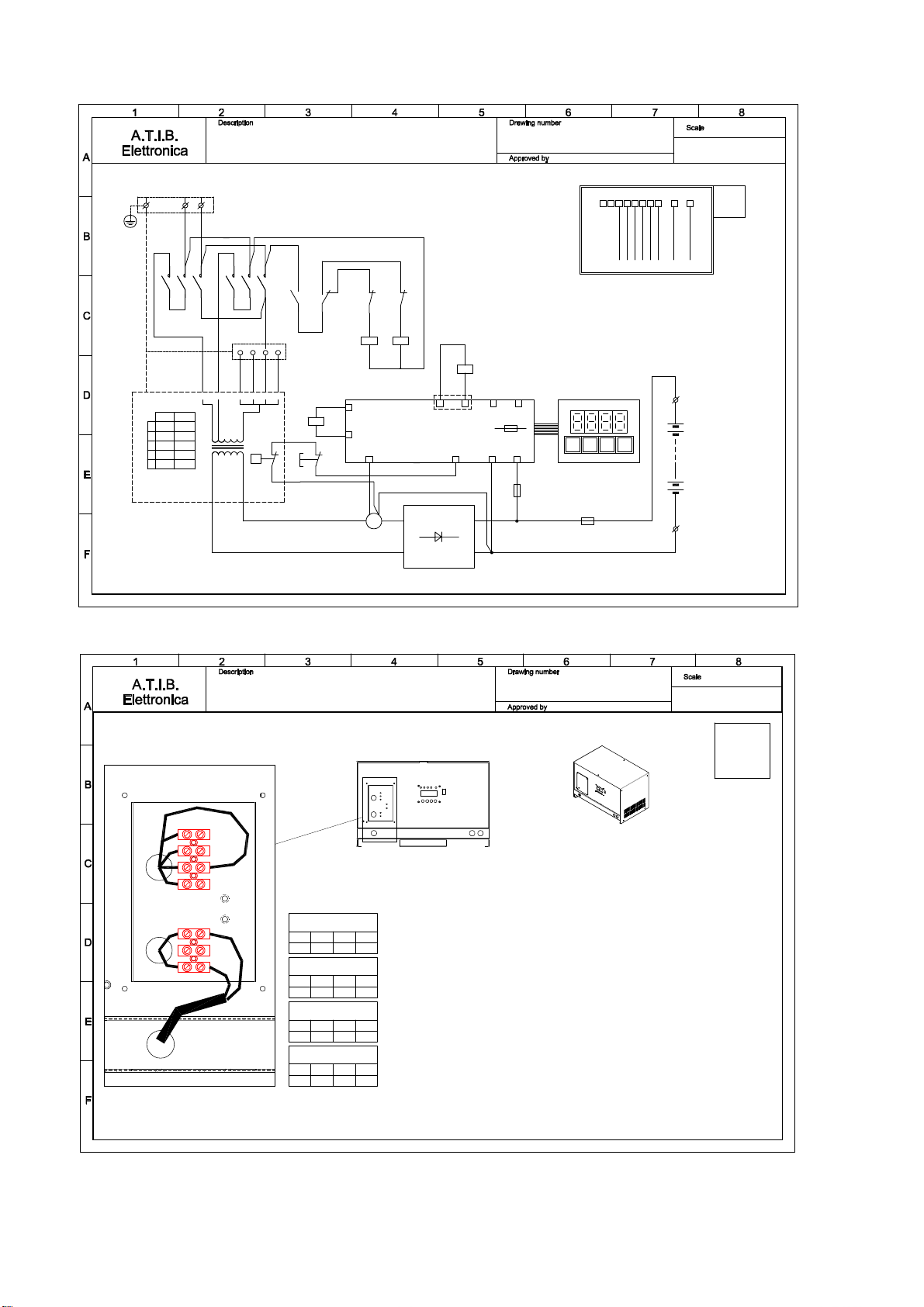
ADVANCED single-phase charger in the P6C cabinet / Chargeur type ADVANCED Monophasé dans le caisson P6c
13 mar 15
150_03_rev00
Advanced
Single phase charger
WH
OFF
t°
BK BN
7
8
RD
AT13
109
BROWN
BROWN
BN
BN
Faston
F1
FwdRew
M
VT
BK
BK
BROWN
BLACK
RED
VIOLET
BN
RD
BK
VT
TERMINAL AT12
1 2 3 4 5 6 7 8
BATTERY FUSE
DIODIES BRIDGE
BATTERY
+BGNDT°R-TA
11V-60Hz
41
6
FUSE
5x20 T500mA
FU3
5
TA
3 4
21109
+B
-B
FU1
(+)
(-)A.C.
A.C.
VD1
KA
GND
TRANSFORMER
POWER
TM1
BU
A2
A1
KM1
3
(E) 120V - 60Hz model 3NAS1 - 5NAS1
AC Main Single phase
(C) 240V - 60Hz model 3NAS2 - 5NAS2 (adaptableto 208V)
Permanently Connected
CARD
G2
AT13
CARD
G1
AT12
L3L2
T3T2
L1
T1
LN
LN
9
KM1
BN
(E)-(C) K
I J L
7
1
L
K
J
I
H(E)
110V
115V
120V
125V
130V
(C)
200V
208V
224V
240V
250V
BK
12Vdc
A1
A2
KA2
14
11
KA2
BN
BN
BU
GND
3 4 5 6
RD
FU5
5x20 F500mA
BN
Advanced
Serie 3N - no Display AT13 (G2)
Serie 5N - with Display AT13 (G2)
2
H
Cabinet P6c
1
7
110V
SETTING
-- - -7
115V
SETTING
-7 - --
120V
SETTING
7- - --
125V
SETTING
-- 7 --
-
110
115 (I)
6
N
L
2
3
4
5
130
7
125
-
115
- -
120
SETTING
130V
AC Main Cable
GND Secondary
GND AC Main M4x16
Neutro N
---
Fase L
110V (H)
120V (J)
125V (K)
130V (L)
120115 125 130110
120115 125 130110
120115 125 130110
120115 125 130110
Mains 128 - 132V
Mains 123 - 127V
Mains 118 - 122V
Mains 113 - 117V
Mains 110 - 112V
ADVANCED models
3NAS1 and 5NAS1 120V-60Hz
in Cabinet P6c
Keep the following information as guidelines. Read carefully the instructions for details
WARNING:
No Voltage into the charger when you move thewires.
Disconnect Mains and Battery plugs
1) First check the AC main Voltage on the Main Terminals and then switch off
2) Check or Move the wires 7 to the closer position (see table)
AC Main
Cable Battery
Cables
434
17 apr 15
155_01 rev00
ADVANCED 120V-60Hz in P6c Cabinet
Single phase chargers
13
PULSE single phase charger in P6C cabinet / Chargeur type PULSE Monophasé dans le caisson P6c
13 mar 15
150_04_rev00
Pulse
Single phase charger
WH
OFF
t°
BK BN
BK
BK
BLACKBK
12Vdc
7
A1
A2
KA1
8
RD
AT13
109
BROWN
BROWN
BN
BN
Faston
F1
FwdRew
M
VT
BK
BK
BROWN
BLACK
RED
VIOLET
BN
RD
BK
VT
BLACKBK
TERMINAL AT12
1 2 3 4 5 6 7 8
BATTERY FUSE
DIODIES BRIDGE
BATTERY
+BGNDT°R-TA
11V-60Hz
41
6
FUSE
5x20 T500mA
FU3
5
TA
3 4
21109
+B
-B
FU1
(+)
(-)A.C.
A.C.
VD1
KA
GND
TRANSFORMER
POWER
TM1
22
21
22
21
WH
RD
BU
KM1
A1
A2
KM2
A2
A1
11
14 12
KA1 KM2
KM1
4
CARD
G2
AT13
CARD
G1
AT12
L3L2
T3T2
L1
T1
10
LN
LN
T3T1
L3L1
9
KM1 KM2
BN
(E)-(C) KI JLG
2
7
1
L
K
J
I
G(E)
Pulse
115V
120V
125V
130V
(C)
Pulse
208V
224V
240V
250V
RD WH
BK
12Vdc
A1
A2
KA2
14
11
KA2
BN
BN
BU
GND
3 4 5 6
8
11
12
RD
FU5
5x20 F500mA
L2
T2
BN
Pulse
Advanced
(E) 120V - 60Hz model 5NPS1
AC Main Single phase
(C) 240V - 60Hz model 5NPS2 (adaptable to 208V)
Permanently Connected
Cabinet P6c
Fase L
---
Neutro N
GND AC Main M4x16
GND Secondary
AC Main Cable
130V
SETTING
-- - 7
5
4
3
2
L
N
-7- -
SETTING
125V
--- 7
SETTING
120V
--7 -
SETTING
115V
7
2
120115 125 130
SETTING
SETTING
SETTING
130V (L)
125V (K)
120V (J)
115 (I)
130125115 120
130125115 120
130125115 120
Mains 113 - 117V
Mains 118 - 122V
Mains 123 - 127V
Mains 128 - 132V
PULSE models
5NPS1 120V-60Hz
in Cabinet P6c
Keep the following information as guidelines. Read carefully theinstructionsfor details
WARNING:
No Voltage into the charger when you move the wires.
Disconnect Mains and Battery plugs
1) First check the AC main Voltage on the Main Terminals and then switch off
2) Check or Move the wires 7 to the closer position(see table)
AC Main
Cable Battery
Cables
434
17 apr 15
155_02 rev00
PULSE 120V-60Hz in P6c Cabinet
Single phase chargers

14
ADVANCED single phase charger in I2c cabinet / Chargeur type ADVANCED monophasé dans le caisson I2c
13 mar 15
150_11 rev.00
Advanced
Single phase charger
WH
OFF
t°
BK BN
7
8
RD
AT13
109
BROWN
BROWN
BN
BN
Faston
F1
FwdRew
M
VT
BK
BK
BROWN
BLACK
RED
VIOLET
BN
RD
BK
VT
TERMINAL AT12
12345678
BATTERY FUSE
DIODIES BRIDGE
BATTERY
+BGNDT°R-TA
11V-60Hz
41
6
FUSE
5x20 T500mA
FU3
5
TA
3 4
21109
+B
-B
FU1
(+)
(-)A.C.
A.C.
VD1
KA
GND
TRANSFORMER
POWER
TM1
11
CARD
G2
AT13
CARD
G1
AT12
L3L2
T3T2
L1
T1
LN
LN
9
KM1
BN
(E)-(C) KI JL
7
1
L
K
J
I
H(E)
110V
115V
120V
125V
130V
(C)
200V
208V
224V
240V
250V
BK
12Vdc
A1
A2
KA2
BN
BN
BU
GND
RD
FU5
5x20 F500mA
Advanced
BU
A2
A1
KM1
14
11
KA2
BN
H
(E) 120V - 60Hz model 3NAS1 - 5NAS1
AC Main Single phase
(C) 240V - 60Hz model 3NAS2 - 5NAS2 (adaptable to 208V)
Permanently Connected Cabinet I2c
Serie 3N - no Display AT13 (G2)
Serie 5N - with Display AT13 (G2)
H I J K L
L N
GND
MAIN
Secondary
GND
250240224208200
C
1 7
AC main Plate
Power Transformer Plate
-
SETTING
240V
-7- -1
C
C
1224
--
208 -
240 7
250
250V
SETTING
200
-
-
SETTING
224V
--- 71
C
C
1 -7 - -
208V
SETTING
-
7
SETTING
200V
--- -1
C
Components Plate
AC Main
Cable
200 250240208 224
200 250240208 224
200 250240208 224
200 250240208 224
ADVANCED models
3NAS2 and 5NAS2 240V-60Hz in Cabinet I2c
Mains 246 - 253V
Mains 231 - 245V
Mains 216 - 230V
Mains 205 - 215V
Mains 200 - 204V
7
435 4 38 PL10
terminal can change in according with power transformer
115120125130
C H I J K L C H I
115
J
120
K
125
L
130
C H
115
I
120
J
125
Battery
Cables
125
K
130
L
Keep the following information asguidelines.
Read carefully the instructions for details
WARNING: No Voltage into the charger when you move the wires.
Disconnect Mains and Battery plugs
1) First check the AC main Voltage on the Main Terminals and then switch off
2) Check or Move the wires 7 to the closer position(see table)
Do NOT move wires 1
17 apr 15
155_07 rev00
ADVANCED 240V-60Hz in I2 Cabinet
Single phase chargers

15
PULSE single phase charger in I2C cabinet / Chargeur type PULSE Monophasé dans le caisson I2c
13 mar 15
150_12 rev.00
Pulse
Single phase charger
WH
OFF
t°
BK BN
BK
BK
BLACKBK
12Vdc
7
A1
A2
KA1
8
RD
AT13
109
BROWN
BROWN
BN
BN
Faston
F1
FwdRew
M
VT
BK
BK
BROWN
BLACK
RED
VIOLET
BN
RD
BK
VT
BLACKBK
TERMINAL AT12
1 2 3 4 5 6 7 8
BATTERY FUSE
DIODIES BRIDGE
BATTERY
+BGNDT°R-TA
11V-60Hz
41
6
FUSE
5x20 T500mA
FU3
5
TA
3 4
21109
+B
-B
FU1
(+)
(-)A.C.
A.C.
VD1
KA
GND
TRANSFORMER
POWER
TM1
22
21
21
22
WH
RD
BU
KM1
A2
A1
KM2
A1
A2
11
14 12
KA1 KM2
KM1
12
CARD
G2
AT13
CARD
G1
AT12
L3L2
T3T2
L1
T1
10
LN
LN
T3T1
L3L1
9
KM1 KM2
BN
(E)-(C) KI JLG
2
7
1
L
K
J
I
G(E)
Pulse
115V
120V
125V
130V
(C)
Pulse
208V
224V
240V
250V
RD WH
BK
12Vdc
A1
A2
KA2
14
11
KA2
BN
BN
BU
GND
8
11
12
RD
FU5
5x20 F500mA
Pulse
Advanced
BN
L2
T2
(E) 120V - 60Hz model 5NPS1
AC Main Single phase
(C) 240V - 60Hz model 5NPS2 (adaptable to 208V)
Permanently Connected Cabinet I2c
G
G
G
115120125130
Battery
Cables
AC Main
Cable
Components Plate
2
G
SETTING
250V
7-- -1
C
2
SETTING
240V
-7- -1
C
C
1 7- - -
224V
SETTING
2
2
SETTING
208V
--7 -1
C
Power Transformer Plate
AC main Plate
721
C G I J K L
GND
Secondary
MAIN
GND NL
250240208 224
224208 240 250
224208 240 250
224208 240 250
Mains 205 - 215V
Mains 216 - 230V
Mains 231 - 245V
Mains 246 - 253V
PULSE models
5NPS2 240V-60Hz in Cabinet I2c
8
L
130
K
125
J
120
I
115
GC
130
L
125
K
120
J
115
IGCLKJIGC
130125120115
435 4 38 PL10
terminal can change in according with power transformer
Keep the following information as guidelines.
Read carefully the instructions for details
WARNING: No Voltage into the charger when you move the wires.
Disconnect Mains and Battery plugs
1) First check the AC main Voltage on the Main Terminals and then switch off
2) Check or Move the wires 7 to the closer position(see table)
Do NOT move wires 1
17 apr 15
155_08 rev00
PULSE 240V-60Hz in I2 Cabinet
Single phase chargers

16
ADVANCED Three phase charger 208-240-480V in I2c cabinet / Chargeur type ADVANCED Triphasé 208-240-480V dans le caisson I2c
12 mar 15
150_23_rev00
Advanced
Three phase charger
WH
BN
BK
t°
OFF
1097 8
BN
BN
BROWN
BROWN
5421 3
RED
BN
RD
VT
BK
BU
BU BLUE
VIOLET
BLACK
GREY
BROWN
6
TERMINAL AT12
F1
Fwd
M
Rew
AT13
Faston
GND
KA
RD
BATTERY FUSE
GY
BATTERY
FUSE
RD
BK
BN
L3
BU
BN BN
GY
L1 L2
BK
VT
DIODIES BRIDGE
POWER
TRANSFORMER
GY
D-Delta
Y-Star
21 3
TM1
7
8
+BGNDT°R-TA
11V-50Hz
10A/250V
41
6
A1
A2
5x20 T500mA
FU3
5
TA
3 4
21109
+B
-B
FU1
(+)
(-)A.C.
A.C.
A.C.
VD1
T3T2T1
L3L2L1
KM1
2 31 97 8
V1 W1
U2 V2
U1
W2
L1 L2L3
J
7 - 8 - 9
K L
KM1
23
CARD
G2
AT13
CARD
G1
AT12
B
C
D
1 - 2 - 3 Y
D
220208200 250240230 500480460
KJ L KJ L KJ LCB D CB D CB D
BK
L3L1 L2
Advanced
GND
FU5
5x20 F500mA
(B) 480V - 60Hz model 3NAT4 - 5NAT4 (default)
AC Main Three phase
Charger can ber adaptable to ...
Permanently Connected
(C) 240V - 60Hz
(D) 208V - 60Hz
Cabinet I2c
Serie 3N - no Display AT13 (G2)
Serie 5N - with Display AT13 (G2)
TM2 40VA
AUXILIARY
TRANSFORMER
0V
0V11V24V
FU2
5x20 F2A
FU4
6,3x32 T500mA
WH VT BU
208V240V
480V
B
A
B
A
B
A
B
AB
A
B
A
B
A
-
C D
1-2-3
B
-
-
C D
1-2-3
B
-
-
B1-2-3
DC
-
1-2-3
CB
-
1-2-3
CB
-
-
B
D
D
DD
D
208V
AUX. CIRCUIT 200V
SETTING
-
L
-
KJ
7-8-9
7-8-9
K L
-
J
--
SETTING 208V
AUX. CIRCUIT
208V
208V
AUX. CIRCUIT 220V
SETTING
-
K L
7-8-9
480V
AUX. CIRCUIT 460V
Y
SETTING
1-2-3
B-
L
-
KJ
7-8-9
7-8-9
K L
-
J
-
B
1-2-3
SETTING
Y
480V
AUX. CIRCUIT
480V
480V
AUX. CIRCUIT 500V
Y
SETTING
1-2-3
B-
K L
7-8-9 7-8-9
LK
--
D
SETTING 250V
AUX. CIRCUIT
240V
240V
AUX. CIRCUIT 240V
SETTING
D
- -
J-
LK
7-8-9
7-8-9
J K
-L
--
DC
1-2-3
SETTING 230V
AUX. CIRCUIT
240V
D
39
28
LKJDB CLKJDB CCB D J K L
7
1
-
J
D
--
C
C
- -
D
C
- -
D J
-J
-
Components Plate
AB
AB
Keep the following information as guidelines. Read carefully the instructions for details
WARNING: No Voltage into the charger when you move the wires. Disconnect Mains and Battery plugs
1) First check the AC main Voltage on the Main Terminals and then switch off
2) Check or Move the "Auxiliary circuit" (A) to the right range (208V - 240V or 480V)
3) Check or Move the "Changer" (B) in the right position (208V and 240 DELTA while 480V STAR ).
4) Check or Move the wires 1-2-3 in the right position (B=480V C=240V D=208V).
5) Check or Move the wires 7-8-9 to the closer position in the selected range. (see table)
AC Main
Cable
Battery
Cables
Secondary
GND
GND
MAIN
STAR - Y
U1 V1 W1
V2U2W2 BA
208V
240V
480V
L1 L2 L3
ADVANCED models
3NAT4 and 5NAT4 480V-60Hz in Cabinet I2c
Mains 491 - 510V Mains 246 - 253V Mains 216 - 225V
Mains 205 - 215VMains 236 - 245VMains 471 - 490V
Mains 450 - 470V Mains 226 - 235V Mains 200 - 204V
9
LKJDCB
130125120115
435 4 34
terminal can change in according with power transformer
115120 125130
B C D J K L
17 apr 15
155_09 rev00
ADVANCED 208-240-480V-60Hz
Three phase chargers in I2 Cabinet

17
PULSE Three phase charger 208-240-480V in I2c cabinet /Chargeur type PULSE Triphasé 208-240-480V dans le caisson I2c
12 mar 15
150_24_rev00
Pulse
Three phase charger
WH
BN
BK
t° OFF
BK
208V
240V
1097 8
BN
BK
BK
BN
BLACK
BLACK
BROWN
BROWN
5421 3
RED
BN
RD
VT
BK
BU
BU BLUE
VIOLET
BLACK
GREY
BROWN
6
TERMINAL AT12
22
21
21
22
12Vdc
BK
F1
Fwd
M
Rew
AT13
Faston
GND
KA
A1
A2
KA1
RD
BATTERY FUSE
WH
RD
GY
BATTERY
FUSE
RD
BK
BN
BU
BN BN
GY
BK
VT
DIODIES BRIDGE
POWER
TRANSFORMER
GY
D-Delta
Y-Star
21 3
TM1
KM1
7
8
A1
A2
KM2
L1 L2 L3
T1 T2 T3
+BGNDT°R-TA
11V-50Hz
10A/250V
41
6
KM2
A1
A2
5x20 T500mA
FU3
5
TA
3 4
21109
+B
-B
FU1
(+)
(-)A.C.
A.C.
A.C.
VD1
0V
0V11V24V
480V
T3T2T1
L3L2L1
KM1
64 52 31 97 8
V1 W1
U2 V2
U1
W2
L1 L2L3
(H)-(J)
(4 - 5 - 6)-(7 - 8 - 9)
(I)-(K) (J)-(L)
KA1
21
24 22
KM2
KM1
24
CARD
G2
AT13
CARD
G1
AT12
B
C
D
1 - 2 - 3 Y
D
220208200 250240230 500480460
KJ L KJ L KJ LIH J IH J IH JCB D CB D CB D
RD WH
BK
L3L1 L2 L3L1 L2
Pulse Advanced
GND
FU5
5x20 F500mA
(B) 480V - 60Hz model 5NPT4 (default)
AC Main Three phase
Charger can ber adaptable to ...
Permanently Connected
(C) 240V - 60Hz
(D) 208V - 60Hz
Cabinet I2c
FU4
6,3x32 T500mA
WH VT BU
TM2 40VA
0V11V24V
FU2
5x20 F2A
AUXILIARY
TRANSFORMER
L3L2L1
480V
240V
208V
D
7-8-9
K L
-4-5-6
I J
--
D
SETTING 240V
AUX. CIRCUIT
240V
H
-
-
H
240V
AUX. CIRCUIT 250V
SETTING
D
- -
KJ
4-5-6 L
7-8-9
I
--
I7-8-9
L
4-5-6
J K
--
D
-
CB
1-2-3
SETTING
Y
500V
AUX. CIRCUIT
480V
H
-
-
H
480V
AUX. CIRCUIT 480V
Y
SETTING
1-2-3
B C
-D
- -
JI
4-5-6 -
LK
7-8-9
-
I7-8-9
L
4-5-6
J K
-
SETTING 220V
AUX. CIRCUIT
208V
H
-
-
H
208V
AUX. CIRCUIT 208V
SETTING
- -
JI
4-5-6 -
LK
7-8-9
D D
D
-
B C
1-2-3
-
B C
1-2-3
-
B1-2-3
DC
-
-
B1-2-3
DC
-
A B
AB
AB
ABABAB
9638521 4 7
CB D H I J K LCB D H I J K LLKJIHDB C
B
A
B
A
-
B1-2-3
DC
--
B
DD 208V
AUX. CIRCUIT 200V
SETTING
-
IH
4-5-6 -
L
-
KJ
7-8-9
480V
AUX. CIRCUIT 460V
Y
SETTING
1-2-3
B C
-D
- -
IH
4-5-6 -
L
-
KJ
7-8-9 7-8-9
J K
-L
-4-5-6
H I
--
DC
1-2-3
SETTING 230V
AUX. CIRCUIT
240V
Components Plate
AB
AB
C
Keep the following information as guidelines. Read carefully the instructions for details
WARNING: No Voltage into the charger when you move the wires. Disconnect Mains and Batteryplugs
1) First check the AC main Voltage on the Main Terminals and then switch off
2) Check or Move the "Auxiliary circuit" (A) to the right range (208V - 240V or 480V)
3) Check or Move the "Changer" (B) in the right position (208V and 240 DELTA while 480V STAR).
4) Check or Move the wires 1-2-3 in the right position (B=480V C=240V D=208V).
5) Check or Move the wires 4-5-6 and 7-8-9 to the closer position in the selected range. (see table)
AC Main
Cable
W2 U2 V2
W1V1U1
STAR - Y
MAIN
GND
GND
Secondary
PULSE models
5NPT4 480V-60Hz in Cabinet I2c
Mains 216 - 225VMains 246 - 253VMains 491 - 510V
Mains 471 - 490V
Mains 450 - 470V Mains 226 - 235V Mains 200 - 204V
Mains 205 - 215VMains 236 - 245V
10
435 4 34
terminal can change in according with power transformer
D H I J K L
Battery
Cables
LKJIHDCB B C
17 apr 15
155_10 rev00
PULSE 208-240-480V-60Hz
Three phase chargers in I2 Cabinet

18
ADVANCED Threphase charger 600V in I2c cabinet. / Chargeur type ADVANCED Triphasé 600V dans le caisson I2c

19
PULSE Threphase charger 600V in I2c cabinet. / Chargeur type PULSE Triphasé 600V dans le caisson I2c
This manual suits for next models
4
Table of contents


