Fostex DV-40 User manual

Service Manual
Model
DVD MASTER RECORDER
SAFETY INSTRUCTIONS
Read instructions - All the safety and operating instruc-
tions should be read before the appliance is operated.
Retain instructions - The safety and operating instructions
should be retained for future reference.
Heed warnings - All warnings on the appliance and in the
operating instructions should be adhered to.
Follow instructions - All operating and use instructions
should be followed.
Water and Moisture - The appliance should not be used
near water - for example, near a bathtub, washbowl,
kitchen sink, laundry tub, in a wet basement, or near a
swimming pool, and the like.
Carts and Stands - The appliance should be used only
with a cart or stand that is recommended by the manufac-
turer.
An appliance and cart combination should be moved with
care. Quick stops, excessive force, and uneven surfaces
may cause the appliance and cart combination to over-
turn.
Wall or Ceiling Mounting - The appliance should be
mounted to a wall or ceiling only as recommended by the
manufacturer.
Ventilation - The appliance should be situated so that its
location or position does not interfere with its proper ven-
tilation. For example, the appliance should not be situ-
ated on a bed, sofa, rug, or similar surface that may block
the ventilation openings; or, placed in a built-in installa-
tion, such as a bookcase or cabinet that may impede the
flow of air through the ventilation openings.
Heat - The appliance should be situated away from heat
sources such as radiators, heat registers, stoves, or other
appliances (including amplifiers) that produce heat.
Power Sources - The appliance should be connected to a
power supply only of the type described in the operating
instructions or as marked on the appliance.
Grounding or Polarization - The precautions that should
be taken so that the grounding or polarization means of
an appliance is not defeated.
Power Cord Protection - Power supply cords should be
routed so that they are not likely to be walked on or
pinched by items placed upon or against them, paying
particular attention to cords at plugs, convenience recep-
tacles, and the point where they exit from the appliance.
Cleaning - The appliance should be cleaned only as rec-
ommended by the manufacturer.
Nonuse Periods - The power cord of the appliance should
be unplugged from the outlet when left unused for a long
period of time.
Object and Liquid Entry - Care should be taken so that
objects do not fall and liquids are not spilled into the en-
closure through openings.
Damage requiring Service - The appliance should be ser-
viced by qualified service personnel when:
A.
B.
C.
D.
E.
Servicing - The user should not attempt to service the ap-
pliance beyond that described in the operating instruc-
tions. All other servicing should be referred to qualified
service personnel.
REFER SERVICING TO QUALIFIED SERVICE PERSONNEL.
CAUTION
RISK OF ELECTRIC SHOCK
DO NOT OPEN
CAUTION: TO REDUCE THE RISK OF ELECTRIC SHOCK,
DO NOT REMOVE COVER (OR BACK).
NO USER-SERVICEABLE PARTS INSIDE.
TO PREVENT ELECTRIC SHOCK, MATCH
WIDE BLADE OF PLUG TO WIDE SLOT,
FULLY INSERT.
POUR ÉVITER LES CHOCS ÉLECTRIQUES,
INTRODUIRE LA LAME LA PLUS LARGE DE
LA FICHE DANS LA BORNE CORRE-
SPONDANTE DE LA PRISE ET POUSSER
JUSQU' AU FOND.
CAUTION:
ATTENTION:
The exclamation point within an equilateral
triangle is intended to alert the user to the
presence of important operating and mainte-
nance (servicing) instructions in the litera-
ture accompanying the appliance.
The lightening flash with arrowhead symbol,
within an equilateral triangle, is intended to
alert the user to the presence of uninsulated
“dangerous voltage” within the product's en-
closure that may be of sufficient magnitude to
constitute a risk of electric shock to persons.
“WARNING”
“TO REDUCE THE RISK OF FIRE OR ELECTRIC SHOCK,
DO NOT EXPOSE THIS APPLIANCE TO RAIN OR MOIS-
TURE.”
1.
2.
3.
4.
5.
6.
7.
8.
The power supply cord or the plug has been damaged;
or
Objects have fallen, or liquid has been spilled into the
appliance; or
The appliance has been exposed to rain; or
The appliance does not appear to operate normally or
exhibits a marked changed in performance; or
The appliance has been dropped, or the enclosure
damaged.
9.
10.
11.
12.
13.
14.
15.
16.
17.

3
Service Manual
TABLE OF CONTENTS
NOTES
* Service mode, parts list and circuit diagrams are given in this manual to assist the service technician
in maintaining Model DV40.
* The following accessories are supplied with DV40 as the standard accessories.
Owner's manual : 8288486000 (for export model)
Owner's manual : 8288487000 (for domestic model)
* Following is the packing material for the Model DV40.
Carton, inner, DV40 : 8228751000
Carton, outer, DV40 : 8228931000
Packing, L, DV40 : 8228475001
Packing, R, DV40 : 8228475002
CAUTION
Parts marked with this sign are safety critical components. They must always be replaced with identical
components. Refer to the Fostex Parts List and ensure exact replacement.
1. SPECIFICATIONS . . . . . . . . . . . . . . . . . . . . . . . . . . . . . . . . . . . . . . .
2. CONTROLS, INDICATORS AND CONNECTORS . . . . . . . . . . . .
3. SOFTWARE UPDATE . . . . . . . . . . . . . . . . . . . . . . . . . . . . . .
4. SERVICE MODE . . . . . . . . . . . . . . . . . . . . . . . . . . . . . . . . . . .
5. EXPLODED VIEW, PCB ASSEMBLY AND PARTS LIST . . . . . .
6. CIRCUIT DIAGRAMS . . . . . . . . . . . . . . . . . . . . . . . . . . . .
7. MAC ADDRESS MANAGEMENT . . . . . . . . . . . . . . . . . . . . . . .
4
8
10
12
24
63
90

4
Service Manual
1. SPECIFICATIONS
SPECIFICATION UNIT
0 dBV = 1 Vr.m.s, 0 dBu = 0.775 Vr.m.s.
INPUT & OUTPUT
Reference Level -12 / -18 / -20 dB (Switchable by SETUP menu)
Analog Input (TR1 ~ 4)
Connector XLR-3-31 type (Pin 1: GND, Pin 2: HOT, Pin 3: COLD)
Input impedance 10 kΩor more
Reference input level +4 dBu
Maximum input level +24 dBu (Reference level setting: -20 dB)
Analog Output (TR1 ~ 4)
Connector XLR-3-32 type (balanced) (Pin 1: GND, Pin 2: HOT, Pin 3: COLD)
Load impedance 600 Ωor more
Reference input level +4 dBu
Maximum input level +24 dBu (Reference level setting: -20 dB)
Monitor Output (TR1 ~ 4)
Connector Φ6 mm phone jack (unbalanced)
Load impedance 10 kΩor more
Reference output level -10 dBV
Maximum output level +10 dBV (Reference level setting: -20 dB)
Phones Output
Connector Φ6 mm TRS phone jack (stereo)
Maximum output level 100 mW (32 Ωload)
Load impedance 8 Ωor more
Digital Input (TR1-2, TR3-4)
Connector XLR-3-31 type (balanced) (Pin 1: GND, Pin 2: HOT, Pin 3: COLD)
Format IEC 60958 PART3 (AES/EBU) or IEC 60958 PART2 (S/P DIF)
Digital Output (TR1-2, TR3-4)
Connector XLR-3-32 type (balanced) (Pin 1: GND, Pin 2: HOT, Pin 3: COLD)
Format IEC 60958 PART3 (AES/EBU) or IEC 60958 PART2 (S/P DIF)
(Selectable by SETUP menu)
GPI Input Activating/Disactivating GPI Input can be selected by SETUP menu.
Connector DIN 5 pin
Pin Assignment Refer to the drawing on page 7.
GPI Output GPI Output is activated only when GPI Input is activated.
Connector DIN 5 pin
Pin Assignment Refer to the drawing on page 7.
TC Input
Connector XLR-3-31 type (balanced) (Pin 1: GND, Pin 2: HOT, Pin 3: COLD)
Format SMPTE/EBU
Transfer rate 2.4 kbit/sec (SMPTE)
Input impedance 20 kΩor more
Reference input level 2 Vp-p
Minimum input level 0.25 Vp-p
TC Output
Connector XLR-3-32 type (balanced) (Pin 1: GND, Pin 2: HOT, Pin 3: COLD)
Format SMPTE/EBU
Output impedance 1 kΩor less
Reference output level 2 Vp-p
Load impedance 600 Ωor more

5
Service Manual
Ethernet port 44.1 / 48 kHz
Connector RJ-45
Format Comply to IEE802.3, 10BASE-T & 100BASE-TX standards
LED indication
10/100 LED is on when connecting to network via 100BASE-TX.
LED is off when connecting to network via 10BASE-T
LINK LED is on when network is recognized.
TX/RX LED is on when transmitting / receiving data.
Video Input
Connector BNC type
Reference input level TTL level (with 75 Ωtermination switch)
Video Thru Direct output of video input
Connector BNC type
9P-REMOTE (RS-422) *
Connector D-DUB 9-pin
Protocol Comply to SONY 9-pin (P2) protocol
DV40 works as a controlled device only.
Pin assignment Refer to the drawing on page 7.
15P-REMOTE (RS-422) *
Connector D-DUB 15-pin
Protocol Comply to SONY 9-pin (P2) protocol
DV40 works as a controlled device only.
Pin assignment Refer to the drawing on page 7.
Word Input**
Connector BNC type
Reference input level TTL level (with 75 Ωtermination switch)
Word Output**
Connector BNC type
Reference output level TTL level
Word Thru Direct output of word input
Connector BNC type
PS/2 Port (x 2)***
RECORD & REPRODUCE
Recording Medium DVD-RAM drive (E-IDE standard)
2.5” hard disk (optional)
Fs & Resolution 16-bit: 44.1 kHz / 48 kHz
24-bit: 44.1 kHz / 48 kHz / 88.2 kHz / 96 kHz / 176.4 kHz / 192 kHz
Crossfade Time 10 msec (default)
OPERATION
Locate Memory
Memory in machine 100 points
Memory in file (Cue Point Chunk/ Region Rec)
100 points
DISPLAY
28 dots bargraph meter x 4 with selectable reference level,
16 digits 7 x 5 character display, 13 digits 7-segment time display

6
Service Manual
DIMENSIONS
141 (H) x 482 (W) x 369 (D) mm
WEIGHT
7.4 kg
USAGE CONDITION
Horizontal, continuous operation
POWER SUPPLY
JPN 100 V AC
USA 120 V AC
UK / EUR 230 V AC
POWER CONSUMPTION
50 W
STANDARD ENVIRONMENT
Standard Temperature 20 ±2 ˚C
Standard Humidity 65 ±5 %
ENVIRONMENTAL CONDITION
Characteristics Guaranteed
Temperature + 5 ~ + 40 ˚C
Humidity 30 ~ 70 %
AC Voltage Deviation ±5 % or less
Operation Guaranteed
Temperature 0 ~ + 45 ˚C
Humidity 85 % or less
AC Voltage Deviation ±10 % or less
CHARACTERISTICS
Overall Frequency Response
Fs: 44.1 / 48 kHz 20 ~ 20,000 Hz ±1 dB
Fs: 88.2 / 96 kHz 20 ~ 40,000 Hz ±2 dB
Fs: 176.4 / 192 kHz 20 ~ 80,000 Hz ±3 dB
S /N Ratio 105 dB or more (Between ADC and DAC, 24-bit, REF: -20 dB, Fs: 48 kHz)
Dynamic Range 105 dB or more (Between ADC and DAC, 24-bit, REF: -20 dB, Fs: 48 kHz)
T.H.D. 0.006 % or less at 1 kHz, - 1 dB
Channel Separation 95 dB or more at 1 kHz, 0 dB (24-bit, REF: -20 dB, Fs: 48 kHz)
Phase Difference between
Channels 20 ˚ or less at 20 kHz
Click Noise - 30 dBV at powering on / off (PEAK)
* : 9P-REMOTE and 15P-REMOTE are connected in parallel. Only either one can be used at a time.
** : Word input / output frequency when Fs is set to 176.4 / 192 kHz is 88.2 / 96 kHz respectively.
*** : The keyboard default scan code must be set to “2”.
Specifications and appearance are subject to change without notice for product improvement.

7
Service Manual
INPUT OUTPUT
GPI
1
2
3
4
51
2
3
4
5
Pin 1 GND
Pin 2 STOP
Pin 3 PLAY
Pin 4 >>
Pin 5 <<
Pin 1 GND
Pin 2 Cue Point 2 Event Output
Pin 3 Cue Point 1 Event Output
Pin 4 Cue Point 3 Event Output
Pin 5 Cue Point 4 Event Output
GPI Input
Pin Assignment GPI Output
Pin Assignment
9P-REMOTE 15P-REMOTE
18
15 9
18
15 9
D-SUB 9P Pin Assignment D-SUB 15P Pin Assignment
Pin 1 Frame GND
Pin 2 Transmit A
Pin 3 Receive B
Pin 4 Receive Common
Pin 5 Spare
Pin 6 Transmit Common
Pin 7 Transmit B
Pin 8 Receive A
Pin 9 Frame GND
Pin 10 NC
Pin 11 NC
Pin 12 NC
Pin 13 NC
Pin 14 NC
Pin 15 DC+12V
(400mA MAX)
Pin 1 Frame GND
Pin 2 Transmit A
Pin 3 Receive B
Pin 4 Receive Common
Pin 5 Spare
Pin 6 Transmit Common
Pin 7 Transmit B
Pin 8 Receive A
Pin 9 Frame GND
GPI Port Pin Assignment
9P & 15P-REMOTE Pin Assignment
8
Service Manual
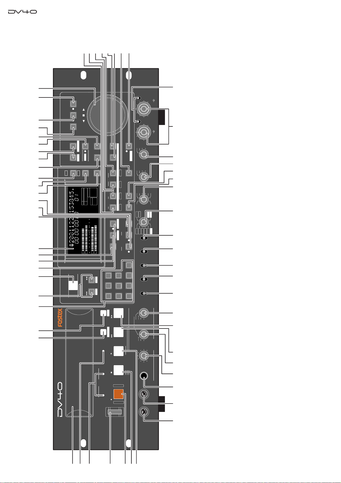
2. CONTROLS, INDICATORS & CONNECTORS
1. [POWER]switch
2. Disk tray
3. [DRIVE (DVD/HD)] indicator
4. [TAPE MODE]indicator
5. [CHASE]([TC SETUP]) key
6. [LIST PLAY]([EDIT]) key
7. [OPEN/CLOSE]key
8. Transport keys
8-a. [RECORD]key
8-b. [STOP]key
8-c. [PLAY]key
8-d. [|<< REWIND]key
8-e. [>>| F.FWD]key
9. Monitor section
9-a. PHONES jack
9-b. Headphones level control
9-c. Monitor track select switch
9-d. Mono track select switch
2-1. TOP PANEL SECTION
10. [MOUSE]connector
11. [KEYBOARD]connector
12. [SKIP/CURSOR |<<, >>|] ([-][+]) keys
13. FL display
14. [MARGIN RESET/CLR]key
15. [DISP LEVEL]key
16. [DISP TIME]key
17. [SETUP]([UTILITY]) key
18. [FILE SEL]([DIRECTORY]) key
19. [SHIFT]key
20. [VARI PITCH]key
21. [JOG]key
22. [SHUTTLE]key
23. [ENTER/YES]key
24. [EXIT/NO]key
25. Jog Dial
26. [MEMORY]([PREVIEW]) key
27. [STORE]([HOLD]) key
28. [CUE POINT]([PREVIEW]) key
29. [DEST-OUT]([PREVIEW]/[TR 4]) key
30. [LOCATE]key
31. [DEST-IN]([PREVIEW]/[TR 3]) key
32. [UNDO]key
33. [SOURCE-OUT]([PREVIEW]/[TR 2]) key
34. [AUDIO EDIT]key
35. [SOURCE-IN]([PREVIEW]/[TR 1]) key
36. [TC RDY]key
37. [SLATE TONE]([TONE REC]) key
38. [AUDIO RDY - INSERT]key
39. [MUTE]([MUTE REC]) key
40. [AUDIO RDY - NEW FILE]key
41. [INPUT MON]key
42. Alphanumeric keys
43. [CONTROL]switch
44. [AUDIO FILE]switch
45. [INPUT]switch
46. [TR MODE]switch
47. [PULL UP/DOWN]switch
48. [SAMPLING FREQ]switch
49. [FRAME RATE]switch
50. [TC GEN MODE]switch
51. [CLOCK]switch
52. Analog input signal controls
53. [BYPASS ON/OFF]switch
SHUTTLEJOGVARI PITCH
IN DSTOUT
symbol
SKIP/CURSOR
LOCATE
ENTER/YESEXIT/NO
DISP
MARGIN
FILE SEL
STORE
AUDIO EDIT UNDO
2
ABC
3
DEF
89
65
PQRS TUV WXYZ
GHI JKL MNO
TC RDY
INSLATE TONEMUTE
INSERT
OPEN/CLOSE
07
4
1
RESET
TIME
LEVEL
MEMORYCUE POINT
SETUP
NEW FILE
INPUT MON
MUTE REC TONE REC PREVIEW
HOLD
DIRECTORY
UTILITY
AUDIO RDY TR1
SOURCE OUT
space
BY-
PASS
ON
OFF
MINMAX MAX
BY-
PASS
ON
OFF
MIN
VIDEO
WORD
INT
24H RUN
REC RUN
FREE RUN
EXT RUN
TR1 INPUT LEVELTR2 TR4TR3CLOCK
30DF
29.97
29.97DF
25
24
23.97
30
RSVD
PULL
48
44.1
48
(kHz)
192
44.1
16BIT
88.2
96
176.4
-0.1%
NORM
+0.1%
MULTI(4TR)
STEREO
MONO
DIGITAL
ANALOG
SDII
BWF
REMOTE
LOCAL
TC GEN MODE
CONTROL UP/DOWN SAMPLING FREQ
TR MODE
INPUT
AUDIO FILE FRAME RATE
DVD MASTER RECORDER
MONO
MAXMIN
POWER
TR4
TR3
TR2
TR1,3+2,4
TR3+4
TR1+2 TR1
LOCATE REC END
LOCATE ABS 0
F FWD
REWIND
PLAY
STOPRECORD
SOURCE PLAY
TC SETUP
LIST PLAYCHASE
EDIT
PHONES
HDDVD
DRIVE
KEYBOARD MOUSE
DIGITAL
TR2 TR3 TR4
SHIFT
DISP
HMSF
4
3
2
1
-INT-
BWF
FORMAT
CLOCK
-0.1%
kHz 4824
FS
BIT
PGM
ABS
∞60 50 42 34 28 2018 12 86543210OL
+
-
TAPE MODE
24BIT
1
2
3
4
56 7
9-a
1011
12 13 14 15 16 17 18 20 21 22
19 23
24 25
26
28
29
31
33
35
41 36 38 403937
9-b 9-c 9-d
8-e
8-a
8-b
8-c
8-d 44 4543
30
27
32 52
515034494847
46
42
53

9
Service Manual
+4dBu
-10dBV +4dBu
-10dBV
+4dBu
-10dBV +4dBu
-10dBV
TR4 TR2
TR3 TR1 TR3 TR1BAL [+4dBu] BAL [+4dBu]
UNBAL
[-10dBV]
UNBAL
[-10dBV]
TR4 TR2
BAL [+4dBu] BAL [+4dBu]
UNBAL
[-10dBV]
UNBAL
[-10dBV]
OUTPUT
THRU
INPUT
10/100
LINK
TX/RX
TR4-3 TR2-1
TR2 TR1
TR1
TR2
1:GND
2:HOT
3:COLD
192kHz
176.4kHz
INPUT OUTPUT
INPUT
75Ω
ON OFF
INPUT
75Ω
ON OFF
TR4-3 TR2-1
TR2 TR1 THRU
THRU OUTPUT
AC IN
1: GND 2: HOT 3: COLD 1: GND 2: HOT 3: COLD
1: GND
2: HOT
3: COLD
15P-REMOTE 9P-REMOTE
GPI
DIGITAL OUTPUT WORD
TIME CODE ETHERNET
ANALOG INPUT BALANCED ANALOG OUTPUT DIGITAL INPUT VIDEO FAN
HI LO
2-A
1-A
1-B
1-C 1-D
2-B
2-C
34 5-A 5-B 6-A 6-C
6-B
78-A 8-B 8-C 8-D
9-A 9-B
10
11
12
2-2. REAR PANEL SECTION
1. Analog input/output section
1-A. ANALOG INPUT (BALANCED) connectors
(TR1 THROUGH TR4)
1-B. Input level switches
1-C. ANALOG OUTPUT (BAL) connectors
(TR1 THROUGH TR4)
1-D. ANALOG OUTPUT (UNBAL) connectors
(TR1 THROUGH TR4)
2. Time code input/output section
2-A. TIME CODE INPUT connector
2-B. TIME CODE THRU connector
2-C. TIME CODE OUTPUT connector
3. Expansion slot
4. ETHERNET port
5. Digital input/output section
5-A. DIGITAL INPUT connectors
5-B. DIGITAL OUTPUT connectors
6. Video clock section
6-A. VIDEO INPUT connector
6-B. 75ΩON/OFF switch
6-C. VIDEO THRU connector
7. AC IN connector
8. Word clock section
8-A. WORD INPUT connector
8-B. 75ΩON/OFF switch
8-C. WORD THRU connector
8-D. WORD OUT connector
9. GPI input/output connectors
9-A. GPI INPUT connector
9-B. GPI OUTPUT connector
10. 9-pin remote connector
11. 15-pin remote connector
12. FAN switch
10
Service Manual
3. SOFTWARE UPDATE
There are flash ROMs mounted on the CPU Module PCB assy (16M), Display PCB assy (8M inside the Display CPU)
and Ether Card PCB assy (8M). The DV40 software can be updated using a CD-ROM or DVD-RAM disk put into the
DV40 internal DVD-RAM drive. Please refer to the following explanation for correct software updating procedures.
3-1. Required Tools
The following tools / equipment are required to update the DV40 software.
1. IBM PC/AT compatible or Macintosh computer
2. CD-R / RW drive with CD burning application software or DVD-RAM drive with UDF formatting software
3. CD-R / CD-RW disk or DVD-RAM disk
4. A Utility software to extract WinZip compressed software update file
3-2. Software Updating Procedures
The following explanation presumes that the WinZip compressed software update file is correctly sent to you via email
and is copied into your computer.
3-2-1. When using CD-R / RW drive & disk
1. Using a utility software, extract a WinZip compressed software update file “DV40VXXX.zip”. (XXX indicates
the software version number.) There are three files extracted as follow.
1) DV40dXXX.HEX (XXX: software version number) for Display PCB
2) dv40eXXX.mot (XXX: software version number) for Ether Card PCB
3) dv40mXXX.mot (XXX: software version number) for Main PCB (CPU Module PCB)
2. Boot up a CD-R burning application software, insert a blank CD-R or CD-RW disk into a CD-R / RW drive
connected to a PC and create a CD-ROM disk in which the above software update files are included. Please
remember that the software update files must be placed in the 1st directory tree and not be included in a folder.
3. After burning, take out the CD-ROM disk with software update files from the drive.
4. Power on DV40, press the OPEN/CLOSE key to open the disk tray and put the disk into the DVD-RAM drive.
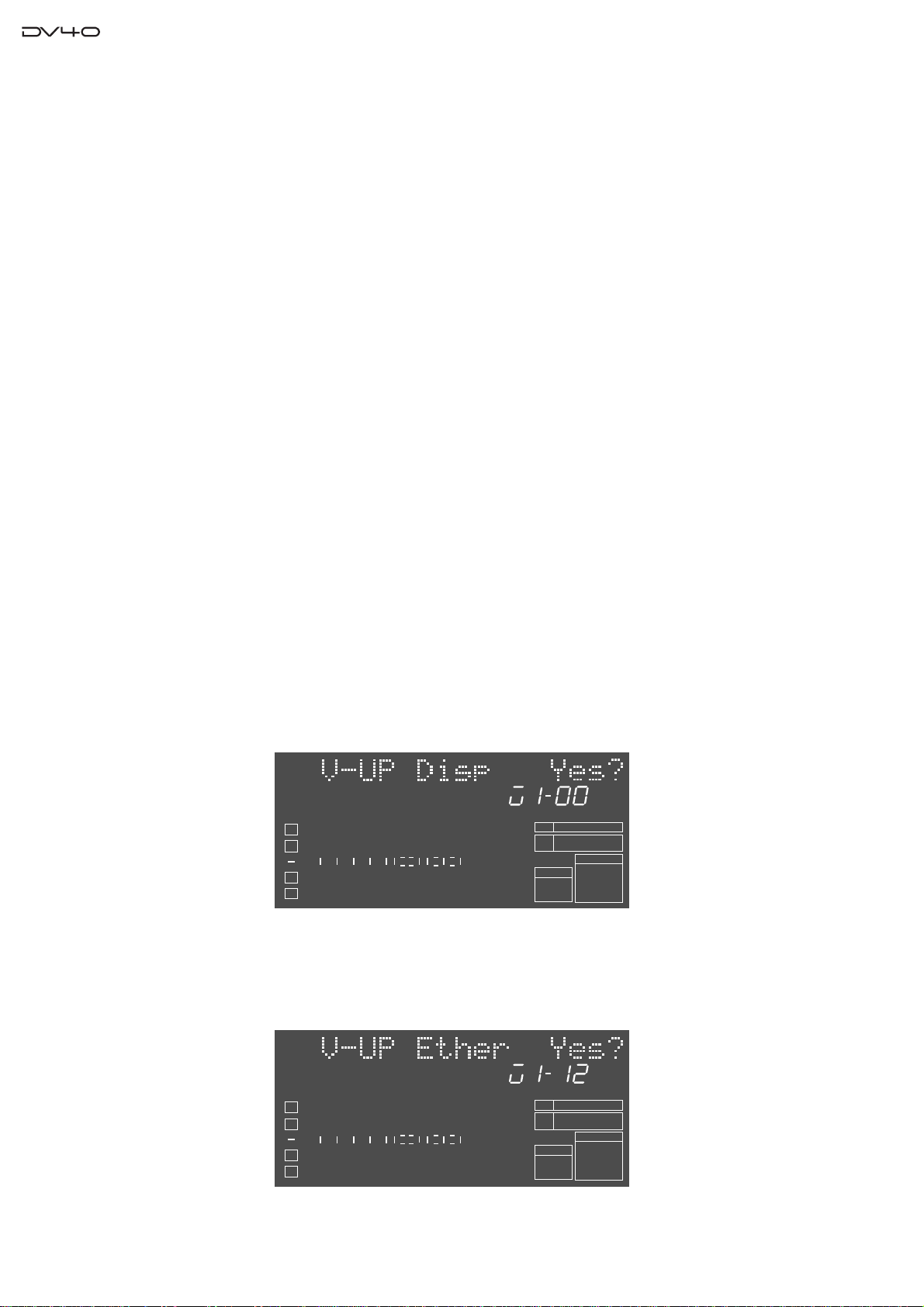
5. “Scan Disk!” and “CD” are displayed. Then, if DV40 properly finds the software update files on the CD-ROM
disk, “V-UP Disp Yes?” will appear on the DV40 FL display shown below. Also the software version number of
the update file is displayed. The example below indicates that there is a “V1.00” software file on the CD-ROM
disk.
4
3
2
1
-INT-
BWF
FORMAT
CLOCK
-0.1%
kHz 4824
FS
BIT
∞
60 50 42 34 28 2018 12 86543210OL
6. Press the ENTER/YES key to update the Display PCB software. While updating the software, the FL display is
blacked out for about 1 minutes but do not power off DV40 and leave it until the next message shows up.
7. After the completion, “V-UP Ether Yes?” and the software version number of the update file will appear on the
DV40 FL display. Press the ENTER/YES key to update the Ether Card PCB assy software. The example below
indicates that there is a “V1.12” software file on the CD-ROM disk.
8. While updating, “Transfer file”, “Erase...” and “Program...” messages are displayed. After the completion with
“Completed!” message, “V-UP Main Yes?” and the software version number of the update file will appear on the
4
3
2
1
-INT-
BWF
FORMAT
CLOCK
-0.1%
kHz 4824
FS
BIT
∞
60 50 42 34 28 2018 12 86543210OL

11
Service Manual
DV40 FL display. Press the ENTER/YES key to update the Main PCB assy (CPU Module PCB) software. The
example below indicates that there is a “V1.12” software file on the CD-ROM disk.
4
3
2
1
-INT-
BWF
FORMAT
CLOCK
-0.1%
kHz 4824
FS
BIT
∞
60 50 42 34 28 2018 12 86543210OL
9. While updating, “Erase ROM” and “Write PGM” messages are displayed. After the completion with “Completed!”
message, DV40 goes back to the normal display.
10. Power off and then back on DV40.
11. Confirm each software version by SETUP mode (Main and Ether Card PCB) and special mode (Display PCB)
explained later.
3-2-2. When using DVD-RAM drive & disk
1. Using a utility software, extract a WinZip compressed software update file “DV40VXXX.zip”. (XXX indicates
the software version number.) There are three files extracted as follow.
1) DV40dXXX.HEX (XXX: software version number) for Display PCB
2) dv40eXXX.mot (XXX: software version number) for Ether PCB
3) dv40mXXX.mot (XXX: software version number) for Main PCB (CPU Module PCB)
2. Boot up a DVD-RAM disk formatting software, insert a blank DVD-RAM disk into an ATAPI or SCSI DVD-
RAM drive connected to a PC, format the disk by UDF1.5 and copy the above software update files to the DVD-
RAM disk. Please remember that the software update files must be placed in the 1st directory tree and not be
included in a folder.
3. After copying, take out the DVD-RAM disk with software update files from the drive.
4. Power on DV40, press the OPEN/CLOSE key to open the disk tray and put the disk into the DVD-RAM drive.
5. “Scan Disk!” and “CD” are displayed. Then, if DV40 properly finds the software update file on the DVD-RAM
disk, “V-UP Disp Yes?” will appear on the DV40 FL display. Also the software version number of the update file
is displayed.
6. Press the ENTER/YES key to update the Display PCB software. While updating the software, the FL display is
blacked out for about 1 minutes but do not power off DV40 and leave it until the next message shows up.
7. After the completion, “V-UP Ether Yes?” and the software version number of the update file will appear on the
DV40 FL display. Press the ENTER/YES key to update the Ether PCB assy software.
8. While updating, “Transfer file”, “Erase...” and “Program...” are displayed. After the completion with “Completed!”
message, “V-UP Main Yes?” and the software version number of the update file will appear on the DV40 FL
display. Press the ENTER/YES key to update the Main PCB assy (CPU Module PCB) software.
9. While updating, “Erase ROM” and “Write PGM” are displayed. After the completion with “Completed!” message,
DV40 goes back to the normal display.
10. Power off and then back on DV40.
11. Confirm each software version by SETUP mode (Main and Ether Card PCB) and special mode (Display PCB)
explained later.
[NOTE]
Instead of using the DVD-RAM drive connected to a PC, the DVD-RAM disk can be formatted using the Format menu
in the DV40 Utility mode ([SHIFT] + [SETUP]). In such a case, regardless of Normal or Tape formatting mode, simply
format the disk. The important thing is to place the software files in the 1st directory tree.
[CAUTION]
1. Please make sure to power off and then back on DV40 and initialize it (See page 14.) after updating the software.
2. When using a DVD-RAM disk for updating the software, please make sure to format it by UDF1.5. If the disk is
formatted by UDF2.0, it might not be correctly recognized by a Macintosh computer.
3. Please remember that all three software files are not necessarily sent to you every time. For example, there is a
case that only the software for Main PCB (CPU Module PCB) and Ether Card PCB are sent to you.
12
Service Manual
4. SERVICE MODE
Various Optional Menus are available on the DV40 Service Mode. Please utilize them while servicing the unit.
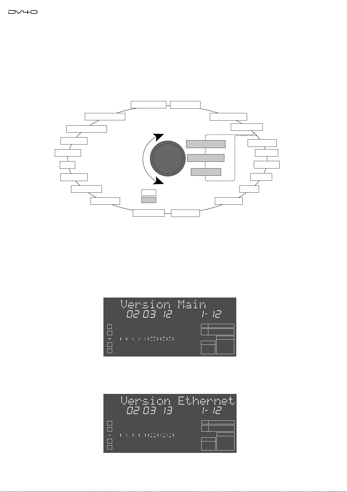
4-1. Putting DV40 into Service Mode
The way to put DV40 into Service Mode is to press the [SETUP] key while holding down the [STOP] key. With this
operation, optional menus “Self Check Sure?”, “Memory Initial?” and “Flash ROM?” will be additionally displayed
between the “Running Time” and “RTC Adjust?” normal Setup menus.
TCP/IP Setup? Version Main
Version Ethernet
Running Time
RTC Adjust?
Contast?
Ref.Level?
D.IN Tr.?
D.Out?
Skip Mode?
Diagnoses?Auto EE MD?
Panel Lock?
RS422 Setp?
Peak Hold?
GPI?
Tone Rec?
Mute Rec?
User Setup Save?
User Setup Load?
Self Check Sure?
Memory Initial ?
Flash ROM?
C.W.
C.C.W.
[STOP]
+
[SETUP]
XXX :Normal SETUP menu
XXX : OPTINAL menu
Rotate the JOG dial, select a required optional menu and press the [ENTER/YES] key to execute.
4-2. Software Version
4-2-1. Software Version of Flash ROM on CPU Module (Main PCB)
The software version can be confirmed by the normal SETUP menu. Just press the [SETUP] key and rotate the jog dial.
The example below indicates that the software version is V1.12 and the programming date is March 12, 2002.
YMD
4
3
2
1
-INT-
BWF
FORMAT
CLOCK
-0.1%
kHz 4824
FS
BIT
SETUP
∞
60 50 42 34 28 2018 12 86543210OL
4-2-2. Software Version of Flash ROM on Ether PCB
The software version can be confirmed by the normal SETUP menu. Just press the [SETUP] key and rotate the jog dial.
The example below indicates that the software version is V1.12 and the programming date is March 13, 2002.
YMD
4
3
2
1
-INT-
BWF
FORMAT
CLOCK
-0.1%
kHz 4824
FS
BIT
SETUP
∞
60 50 42 34 28 2018 12 86543210OL
13
Service Manual
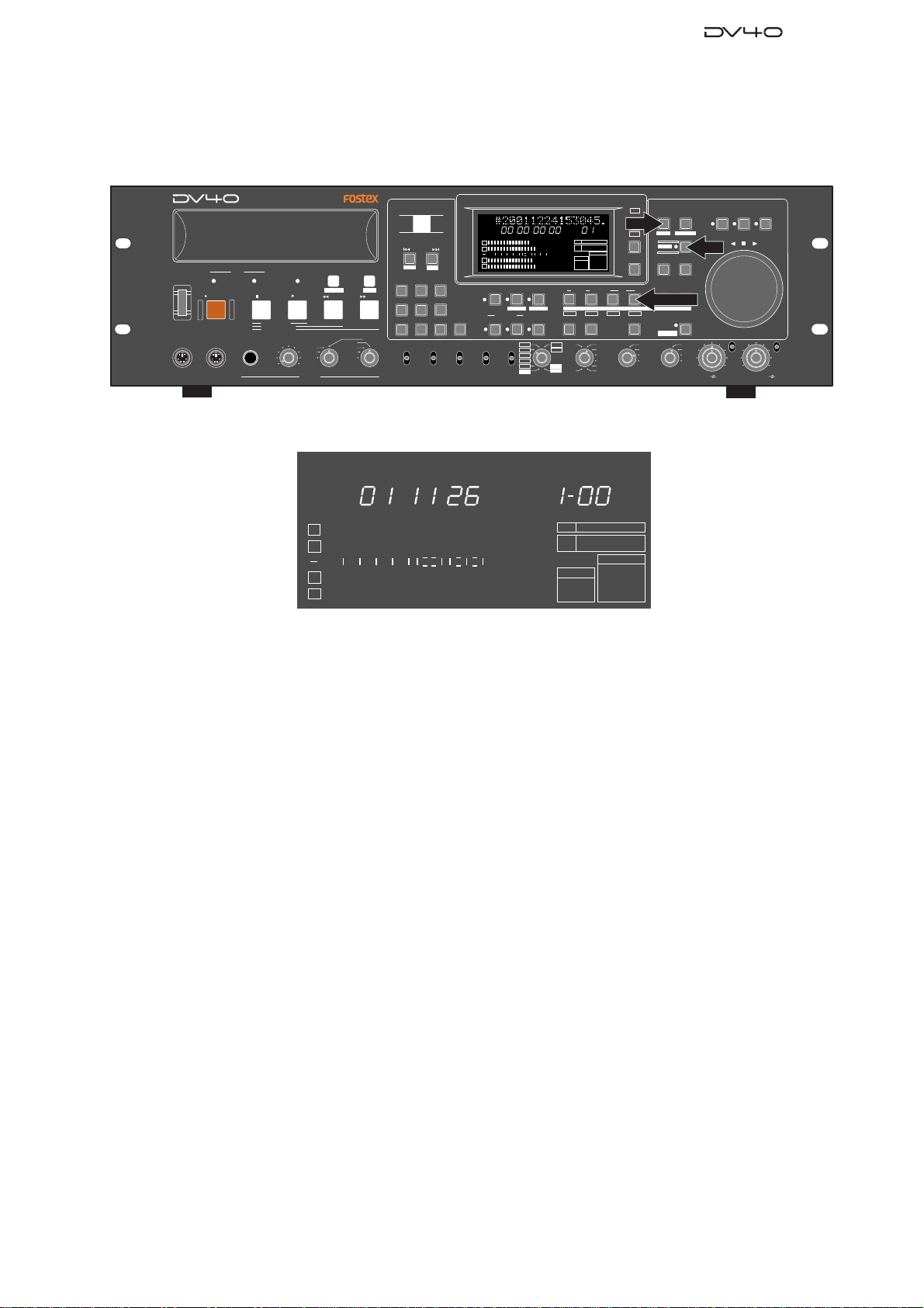
4-2-3. Software Version of Flash ROM on Display PCB
The way to check the software version of Flash ROM on the Display PCB is different from the one on the CPU Module
PCB (Main PCB) or Ether Card PCB. As indicated in the drawing below, press the [SETUP], [SHIFT] and [DEST
OUT] at a time.
SHUTTLEJOGVARI PITCH
IN DSTOUT
symbol
SKIP/CURSOR
LOCATE
ENTER/YESEXIT/NO
DISP
MARGIN
FILE SEL
STORE
AUDIO EDIT UNDO
2
ABC
3
DEF
89
65
PQRS TUV WXYZ
GHI JKL MNO
TC RDY
INSLATE TONEMUTE
INSERT
OPEN/CLOSE
07
4
1
RESET
TIME
LEVEL
MEMORYCUE POINT
SETUP
NEW FILE
INPUT MON
MUTE REC TONE REC
PREVIEW
HOLD
DIRECTORY
UTILITY
AUDIO RDY TR1
SOURCE OUT
space
BY-
PAS S
ON
OFF
MINMAX MAX
BY-
PASS
ON
OFF
MIN
VIDEO
WORD
INT
24H RUN
REC RUN
FREE RUN
EXT RUN
TR1 INPUT LEVELTR2 TR4TR3CLOCK
30DF
29.97
29.97DF
25
24
23.97
30
RSVD
PULL
48
44.1
48
(kHz)
192
44.1
16BIT
88.2
96
176.4
-0.1%
NORM
+0.1%
MULTI(4TR)
STEREO
MONO
DIGITAL
ANALOG
SDII
BWF
REMOTE
LOCAL
TC GEN MODE
CONTROL UP/DOWN SAMPLING FREQ
TR MODE
INPUT
AUDIO FILE FRAME RATE
DVD MASTER RECORDER
MONO
MAXMIN
POWER
TR4
TR3
TR2
TR1,3+2,4
TR3+4
TR1+2 TR1
LOCATE REC END
LOCATE ABS 0
F FWD
REWIND
PLAY
STOPRECORD
SOURCE PLAY
TC SETUP
LIST PLAYCHASE
EDIT
PHONES
HDDVD
DRIVE
KEYBOARD MOUSE
DIGITAL
TR2 TR3 TR4
SHIFT
DISP
HMSF
4
3
2
1
-INT-
BWF
FORMAT
CLOCK
-0.1%
kHz 4824
FS
BIT
PGM
ABS
∞
60 50 42 34 28 2018 12 86543210OL
+
-
TAPE MODE
24BIT
SHIFT
SETUP
DEST-OUT/TR4
YMD
4
3
2
1
-INT-
BWF
FORMAT
CLOCK
-0.1%
kHz 4824
FS
BIT
∞
60 50 42 34 28 2018 12 86543210OL
The example below indicates that the software version is V1.00 and the programming date is November 26, 2001.
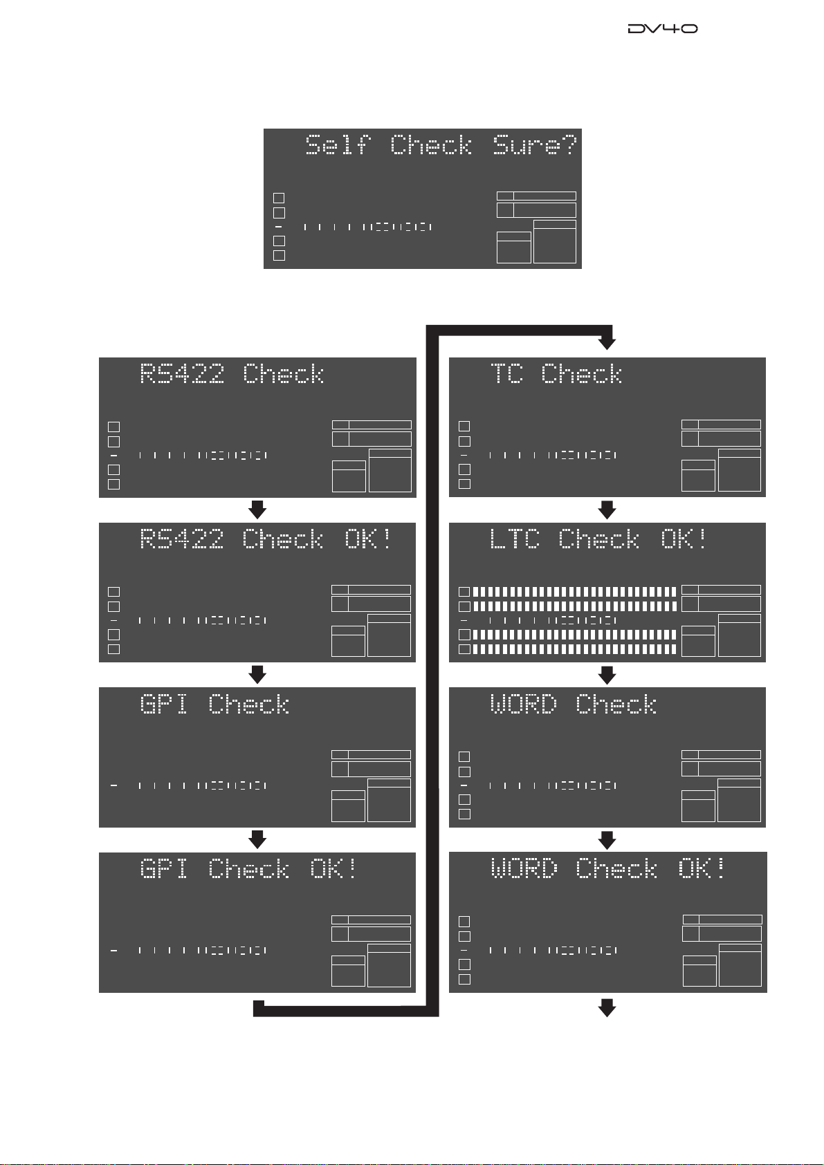
4-3. Self Check Mode
The Self Check mode helps you check if DV40 works properly or not and which circuits are causing a problem. In this
mode, the following circuit are tested in order.
• RS422 9-pin circuit
• GPI circuit
• TC circuit
• WORD circuit (Fs: 48kHz)
• WORD circuit (Fs: 96kHz)
• WORD circuit (Fs: 192kHz)
• ANALOG CH1 circuit
• ANALOG CH2 circuit
• ANALOG CH3 circuit
• ANALOG CH4 circuit
• DIGITAL CH1/2 circuit
• DIGITAL CH3/4 circuit
• Keyboard
• Mouse

14
Service Manual
4-3-1. Preparation
Before executing the Self Check mode, prepare the following cables, etc and connect them as indicated below.
• 7 x XLR (male) - XLR (female) balanced cables
ANALOG IN CH1 - ANALOG OUT CH1
ANALOG IN CH2 - ANALOG OUT CH2
ANALOG IN CH3 - ANALOG OUT CH3
ANALOG IN CH4 - ANALOG OUT CH4
DIGITAL IN CH1/2 - DIGITAL OUT CH1/2
DIGITAL IN CH3/4 - DIGITAL OUT CH3/4
TC IN - TC OUT
• 1 x BNC - BNC cable
WORD IN - WORD OUT
• 1 x D-SUB 9-pin male connector (Pin-2 & 8 / Pin 3 & 7 are shortened.)
To RS-422 9-pin connector
• 1 x MIDI cable
GPI IN - GPI OUT
• PS/2 keyboard
To KEYBOARD connector
• PS/2 mouse
To MOUSE connector
<Connection on DV40 Front Panel side>
<Connection on DV40 Rear Panel side>
SHUTTLEJOGVARI PITCH
IN DSTOUT
symbol
SKIP/CURSOR
LOCATE
ENTER/YESEXIT/NO
DISP
MARGIN
FILE SEL
STORE
AUDIO EDIT UNDO
2
ABC
3
DEF
89
65
PQRS TUV WXYZ
GHI JKL MNO
TC RDY
INSLATE TONEMUTE
INSERT
OPEN/CLOSE
07
4
1
RESET
TIME
LEVEL
MEMORYCUE POINT
SETUP
NEW FILE
INPUT MON
MUTE REC TONE REC PREVIEW
HOLD
DIRECTORY
UTILITY
AUDIO RDY TR1
SOURCE OUT
space
BY-
PASS
ON
OFF
MINMAX MAX
BY-
PAS S
ON
OFF
MIN
VIDEO
WORD
INT
24H RUN
REC RUN
FREE RUN
EXT RUN
TR1 INPUT LEVELTR2 TR4TR3CLOCK
30DF
29.97
29.97DF
25
24
23.97
30
RSVD
PULL
48
44.1
48
(kHz)
192
44.1
16BIT
88.2
96
176.4
-0.1%
NORM
+0.1%
MULTI(4TR)
STEREO
MONO
DIGITAL
ANALOG
SDII
BWF
REMOTE
LOCAL
TC GEN MODE
CONTROL UP/DOWN SAMPLING FREQ
TR MODE
INPUT
AUDIO FILE FRAME RATE
DVD MASTER RECORDER
MONO
MAXMIN
POWER
TR4
TR3
TR2
TR1,3+2,4
TR3+4
TR1+2 TR1
LOCATE REC END
LOCATE ABS 0
F FWD
REWIND
PLAY
STOPRECORD
SOURCE PLAY
TC SETUP
LIST PLAYCHASE
EDIT
PHONES
HDDVD
DRIVE
KEYBOARD MOUSE
DIGITAL
TR2 TR3 TR4
SHIFT
DISP
HMSF
4
3
2
1
-INT-
BWF
FORMAT
CLOCK
-0.1%
kHz 4824
FS
BIT
PGM
ABS
∞60 50 42 34 28 2018 12 86543210OL
+
-
TAPE MODE
24BIT
PS/2 keyboard PS/2 mouse
+4dBu
-10dBV +4dBu
-10dBV
+4dBu
-10dBV +4dBu
-10dBV
TR4 TR2
TR3 TR1 TR3 TR1BAL [+4dBu] BAL [+4dBu]
UNBAL
[-10dBV]
UNBAL
[-10dBV]
TR4 TR2
BAL [+4dBu] BAL [+4dBu]
UNBAL
[-10dBV]
UNBAL
[-10dBV]
OUTPUT
THRU
INPUT
10/100
LINK
TX/RX
TR4-3 TR2-1
TR2 TR1
TR1
TR2
1:GND
2:HOT
3:COLD
192kHz
176.4kHz
INPUT OUTPUT
INPUT
75Ω
ON OFF
INPUT
75Ω
ON OFF
TR4-3 TR2-1
TR2 TR1
THRU
THRU OUTPUT
AC IN
1: GND 2: HOT 3: COLD 1: GND 2: HOT 3: COLD
1: GND
2: HOT
3: COLD
15P-REMOTE 9P-REMOTE
GPI
DIGITAL OUTPUT WORD
TIME CODE ETHERNET
ANALOG INPUT BALANCED ANALOG OUTPUT DIGITAL INPUT VIDEO FAN
HI LO
XLR balanced cable
XLR balanced cable
XLR balanced cable
XLR balanced cable
XLR balanced cable
MIDI cable
BNC cable
BNC cable
BNC cable
D-SUB 9-pin male connector
with shorted pins
Pin-2 (Transmit A) & Pin-8 (Receive A)
Pin-3 (Receive B) & Pin-7 (Transmit B)
15
Service Manual
4
3
2
1
-INT-
BWF
FORMAT
CLOCK
-0.1%
kHz 4824
FS
BIT
SETUP
∞
60 50 42 34 28 2018 12 86543210OL
4
3
2
1
-INT-
CLOCK
kHz 96
24
FS
BIT
DIGITAL
∞
60 50 42 34 28 2018 12 86543210OL
BWF
FORMAT
4
3
2
1
-INT-
CLOCK
kHz 96
24
FS
BIT
DIGITAL
∞
60 50 42 34 28 2018 12 86543210OL
BWF
FORMAT
4
3
2
1
DIGITAL
-EXT-
CLOCK
kHz 96
24
FS
BIT
DIGITAL
SETUP
∞
60 50 42 34 28 2018 12 86543210OL
BWF
FORMAT
4
3
2
1
DIGITAL
-EXT-
CLOCK
kHz 96
24
FS
BIT
DIGITAL
SETUP
∞
60 50 42 34 28 2018 12 86543210OL
BWF
FORMAT
4
3
2
1
-INT-
CLOCK
kHz 96
24
FS
BIT
DIGITAL
∞
60 50 42 34 28 2018 12 86543210OL
BWF
FORMAT
4
3
2
1
24
BIT
∞
60 50 42 34 28 2018 12 86543210OL
BWF
FORMAT
kHz 48
FS
-INT-
CLOCK
4
3
2
1
24
BIT
∞
60 50 42 34 28 2018 12 86543210OL
BWF
FORMAT
kHz 48
FS
-INT-
CLOCK
4-3-2. Executing Self Check mode
Press the [ENTER/YES] key while “?” flashes.
4
3
2
1
-INT-
CLOCK
kHz 96
24
FS
BIT
DIGITAL
∞
60 50 42 34 28 2018 12 86543210OL
BWF
FORMAT
Continue to next page
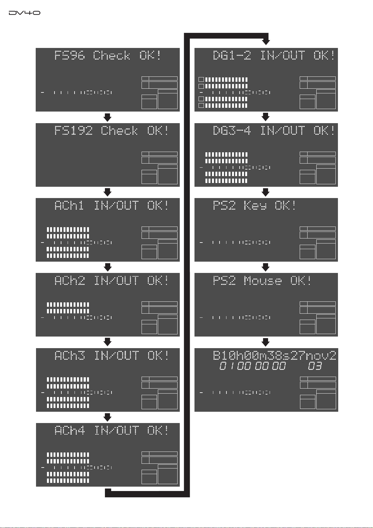
If DV40 works properly, the followings appear on the FL display and it automatically goes back to the normal display.
16
Service Manual
4
3
2
1
-INT-
CLOCK
kHz 192
24
FS
BIT
DIGITAL
∞
60 50 42 34 28 2018 12 86543210OL
FORMAT
4
3
2
1
-INT-
CLOCK
kHz 192
24
FS
BIT
DIGITAL
∞
60 50 42 34 28 2018 12 86543210OL
FORMAT
4
3
2
1
-INT-
CLOCK
-0.1%
kHz 192
24
FS
BIT
DIGITAL
∞
60 50 42 34 28 2018 12 86543210OL
BWF
FORMAT
4
3
2
1
-INT-
CLOCK
-0.1%
kHz 96
24
FS
BIT
DIGITAL
∞
60 50 42 34 28 2018 12 86543210OL
BWF
FORMAT
4
3
2
1
-INT-
CLOCK
kHz 96
24
FS
BIT
DIGITAL
∞
60 50 42 34 28 2018 12 86543210OL
BWF
FORMAT
4
3
2
1
-INT-
CLOCK
kHz 96
24
FS
BIT
DIGITAL
∞
60 50 42 34 28 2018 12 86543210OL
DVD
BWF
FORMAT
HMSF
4
3
2
1
DIGITAL
VIDEO
WORD
-EXT-
-INT-
CLOCK
kHz 4824
FS
BIT
PGM
DIGITAL
LTC
∞
60 50 42 34 28 2018 12 86543210OL
DVD
BWF
SDII
FORMAT
CD
4
3
2
1
-INT-
CLOCK
kHz 96
24
FS
BIT
DIGITAL
∞
60 50 42 34 28 2018 12 86543210OL
BWF
FORMAT
4
3
2
-INT-
CLOCK
kHz 192
24
FS
BIT
BWF
FORMAT
1DIGITAL
4
3
2
1
-INT-
CLOCK
kHz 192
24
FS
BIT
DIGITAL
∞
60 50 42 34 28 2018 12 86543210OL
FORMAT
4
3
2
1
-INT-
CLOCK
kHz 192
24
FS
BIT
DIGITAL
∞
60 50 42 34 28 2018 12 86543210OL
FORMAT

17
Service Manual
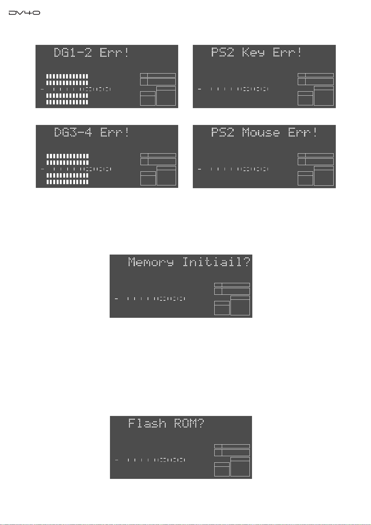
4-3-2. Error display examples
The followings are error display examples. Please remember that pressing the [ENTER/YES] key will retry each
checking item and pressing the [EXIT/NO] key will skip each checking item and go on to the next one.
4
3
2
1
-INT-
CLOCK
kHz 96
24
FS
BIT
DIGITAL
∞
60 50 42 34 28 2018 12 86543210OL
BWF
FORMAT
• Error on RS422 circuitry
4
3
2
1
DIGITAL
-EXT-
CLOCK
kHz 96
24
FS
BIT
DIGITAL
SETUP
∞
60 50 42 34 28 2018 12 86543210OL
BWF
FORMAT
• Error on GPI circuitry
4
3
2
1
-INT-
CLOCK
kHz 96
24
FS
BIT
DIGITAL
∞
60 50 42 34 28 2018 12 86543210OL
BWF
FORMAT
• Error on TC circuitry
4
3
2
1
24
BIT
∞
60 50 42 34 28 2018 12 86543210OL
BWF
FORMAT
kHz 48
FS
-INT-
CLOCK
• Error on WORD circuitry (48kHz)
4
3
2
1
-INT-
CLOCK
kHz 96
24
FS
BIT
DIGITAL
∞
60 50 42 34 28 2018 12 86543210OL
BWF
FORMAT
• Error on WORD circuitry (96kHz)
4
3
2
-INT-
CLOCK
kHz 192
24
FS
BIT
BWF
FORMAT
1DIGITAL
4
3
2
1
-INT-
CLOCK
kHz 192
24
FS
BIT
DIGITAL
∞
60 50 42 34 28 2018 12 86543210OL
BWF
FORMAT
4
3
2
1
-INT-
CLOCK
kHz 192
24
FS
BIT
DIGITAL
∞
60 50 42 34 28 2018 12 86543210OL
BWF
FORMAT
4
3
2
1
-INT-
CLOCK
kHz 192
24
FS
BIT
DIGITAL
∞
60 50 42 34 28 2018 12 86543210OL
BWF
FORMAT
4
3
2
1
-INT-
CLOCK
kHz 192
24
FS
BIT
DIGITAL
∞
60 50 42 34 28 2018 12 86543210OL
BWF
FORMAT
• Error on WORD circuitry (192kHz)
• Error on Analog input & output circuit (CH1)
• Error on Analog input & output circuit (CH2)
• Error on Analog input & output circuit (CH3)
• Error on Analog input & output circuit (CH4)
18
Service Manual
4
3
2
1
-INT-
CLOCK
kHz 96
24
FS
BIT
DIGITAL
∞
60 50 42 34 28 2018 12 86543210OL
BWF
FORMAT
• Error on DIGITAL input and output circuitry (CH 1/2) • Error on PS2 keyboard circuitry
4
3
2
1
-INT-
CLOCK
kHz
24
BIT
DIGITAL
∞
60 50 42 34 28 2018 12 86543210OL
BWF
FORMAT
192
FS
4
3
2
1
-INT-
CLOCK
kHz 96
24
FS
BIT
DIGITAL
∞
60 50 42 34 28 2018 12 86543210OL
BWF
FORMAT
• Error on DIGITAL input and output circuitry (CH 3/4) • Error on PS2 mouse circuitry
4
3
2
1
-INT-
CLOCK
kHz 96
24
FS
BIT
DIGITAL
∞
60 50 42 34 28 2018 12 86543210OL
BWF
FORMAT
4
3
2
1
-INT-
CLOCK
kHz 96
24
FS
BIT
DIGITAL
∞
60 50 42 34 28 2018 12 86543210OL
DVD
BWF
FORMAT
4-4. Memory Initialize
Executing this menu initializes the setting in each SETUP menu and MEMORY (time information of Last Play, Last
Record In / Out and Memory # 04 ~ 99). To do so, press the [ENTER/YES] key while “?” flashes.
4
3
2
-INT-
BWF
FORMAT
CLOCK
kHz 4824
FS
BIT
SETUP
∞
60 50 42 34 28 2018 12 86543210OL
1DIGITAL
4-5. Flash ROM
There is a Flash ROM Card PCB prepared for the CPU Module and Ether Card PCBs. The Flash ROM Card PCB is
used if something wrong happens while updating the software (e.g. power shutdown, blackout). The Flash ROM Card
PCB allows to boot up DV40, copy the system software in the Flash ROM Card PCB to the Flash ROM on the CPU
Module and Ether Card PCBs using this “Flash ROM” Service Menu. Furthermore, you can rewrite the program inside
the Flash ROM on the Flash ROM Card PCB. In other words, by rewriting the program, only one Flash ROM PCB can
work for both the CPU Module and Ether Card PCBs. Refer to the following procedures.
4
3
2
-INT-
BWF
FORMAT
CLOCK
kHz 4824
FS
BIT
SETUP
∞
60 50 42 34 28 2018 12 86543210OL
1DIGITAL

19
Service Manual
4-5-1. Boot Up using Flash ROM Card PCB & Rewriting Flash ROM Program on CPU Module
& Ether Card PCBs
1. Power off DV40 and disconnect the AC cable from the AC IN socket.
2. Open up the top cover.
3. Set the SW S1 on the Flash ROM PCB to “EXT
(FLASH)” side and plug it into either the PCB
assy which cannot be correctly booted up (CPU
Module PCB: J4 50-pin connector, Ether Card
PCB: J300 50-pin connector).
4. Connect the AC cable and power on DV40.
In this condition, DV40 is booted up using the
program inside the Flash ROM on the Flash ROM PCB.
5. Put DV40 into the Service Mode by pressing the [SETUP] key while holding down the [STOP] key and select the
“Flash ROM?” menu.
6. While “?” flashes, press the [ENTER/YES] key.
7. “FlashWrite Sure?” appears on the FL display. Press the [ENTER/YES] key again. The message “ERASE ROM”
and “Write PGM” appear on the FL display while copying the program.
With “Completed!” message, the program inside the Flash ROM on the Flash ROM Card PCB has been successfully
copied to the Flash ROM on either the CPU Module or Ether Card PCB.
8. After confirming that DV40 is correctly booted up, copy the latest software to the CD-ROM or DVD-RAM disk
and update accordingly.
4-5-2. Rewriting Flash ROM Program on Flash ROM Card PCB
[NOTE]
In order to rewrite the Flash ROM program on the Flash ROM Card PCB, preparing DV40 which is booted up
correctly is required.
1. Power off DV40 and disconnect the AC cable from the AC IN socket.
2. Open up the top cover.
3. Set the SW S1 on the Flash ROM PCB to “INT”
side and plug it into either the CPU Module or
Ether Card PCB from which you would like to
transfer the program to the Flash ROM on the
Flash ROM Card PCB.
4. Connect the AC cable and power on DV40.
In this condition, DV40 is booted up using the
program inside the Flash ROM on the CPU Module or Ether Card PCB.
5. Put DV40 into Service Mode by pressing the [SETUP] key while holding down the [STOP] key and select the
“Flash ROM?” menu.
6. While “?” flashes, press the [ENTER/YES] key.
7. “FlashWrite Sure?” appears on the FL display. Press the [ENTER/YES] key again. The message “ERASE ROM”
and “Write PGM” appear on the FL display while copying the program.
With “Completed!” message, the program inside the Flash ROM on either the CPU Module or Ether Card PCB
has been successfully copied to the Flash ROM on the Flash ROM Card PCB.
[CAUTION]
If power shutdown or blackout occurs while updating the Flash ROM program on the Display PCB assy and the
updating procedures are halted, replacing whole the PCB assy might be required. This is because the Display PCB
assy uses the flash ROM inside the Display CPU. There is no connector to connect the Flash ROM Card PCB assy
on the Display PCB.
Flash ROM Card PCB
SW S1
EXT
(FLASH)
INT
DV40
BOOTUP
Flash
ROM
CPU Module PCB
Ether Card PCB
Flash
ROM
Flash
ROM
Copy
Program.
Copy
Program.
Flash ROM Card PCB
SW S1
EXT
(FLASH)
INT
DV40
BOOTUP
Flash
ROM
CPU Module PCB
Ether Card PCB
Flash
ROM
Flash
ROM
Copy
Program.
Copy
Program.
20
Service Manual
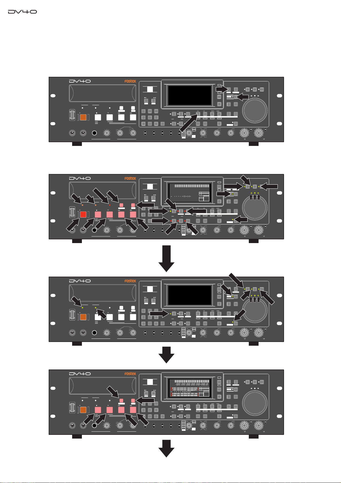
4-7. Display / Key / SW Test
This mode tests if all the FL display segments, LEDs, keys and switches on the DV40 front panel are correctly working.
4-7-1. FL Display and LED Test
Press the [SHIFT], [SETUP] and [SOURCE IN] key.
If DV40 works correctly, every time [SHUTTLE] key is pressed, keys and LEDs will be lit in the following manner.
< Key & LED lit pattern >
SHUTTLEJOGVARI PITCH
IN DSTOUT
symbol
SKIP/CURSOR
LOCATE
ENTER/YESEXIT/NO
DISP
MARGIN
FILE SEL
STORE
AUDIO EDIT UNDO
2
ABC
3
DEF
89
65
PQRS TUV WXYZ
GHI JKL MNO
TC RDY
INSLATE TONEMUTE
INSERT
OPEN/CLOSE
07
4
1
RESET
TIME
LEVEL
MEMORYCUE POINT
SETUP
NEW FILE
INPUT MON
MUTE REC TONE REC
PREVIEW
HOLD
DIRECTORY
UTILITY
AUDIO RDY TR1
SOURCE OUT
space
BY-
PASS
ON
OFF
MINMAX MAX
BY-
PASS
ON
OFF
MIN
VIDEO
WORD
INT
24H RUN
REC RUN
FREE RUN
EXT RUN
TR1 INPUT LEVELTR2 TR4TR3CLOCK
30DF
29.97
29.97DF
25
24
23.97
30
RSVD
PULL
48
44.1
48
(kHz)
192
44.1
16BIT
88.2
96
176.4
-0.1%
NORM
+0.1%
MULTI(4TR)
STEREO
MONO
DIGITAL
ANALOG
SDII
BWF
REMOTE
LOCAL
TC GEN MODE
CONTROL UP/DOWN SAMPLING FREQ
TR MODE
INPUT
AUDIO FILE FRAME RATE
DVD MASTER RECORDER
MONO
MAXMIN
POWER
TR4
TR3
TR2
TR1,3+2,4
TR3+4
TR1+2 TR1
LOCATEREC END
LOCATEABS 0
F FWD
REWIND
PLAY
STOPRECORD
SOURCE PLAY
TC SETUP
LIST PLAYCHASE
EDIT
PHONES
HDDVD
DRIVE
KEYBOARD MOUSE
DIGITAL
TR2 TR3 TR4
SHIFT
DISP
+
-
TAPE MODE
24BIT
SETUP
SHIFT
SOURCEIN/TR1
SHUTTLEJOGVARI PITCH
IN DSTOUT
symbol
SKIP/CURSOR
LOCATE
ENTER/YESEXIT/NO
DISP
MARGIN
FILE SEL
STORE
AUDIO EDIT UNDO
2
ABC
3
DEF
89
65
PQRS TUV WXYZ
GHI JKL MNO
TC RDY
INSLATE TONEMUTE
INSERT
OPEN/CLOSE
07
4
1
RESET
TIME
LEVEL
MEMORYCUE POINT
SETUP
NEW FILE
INPUT MON
MUTE REC TONE REC
PREVIEW
HOLD
DIRECTORY
UTILITY
AUDIO RDY TR1
SOURCE OUT
space
BY-
PASS
ON
OFF
MINMAX MAX
BY-
PASS
ON
OFF
MIN
VIDEO
WORD
INT
24H RUN
REC RUN
FREE RUN
EXT RUN
TR1 INPUT LEVELTR2 TR4TR3CLOCK
30DF
29.97
29.97DF
25
24
23.97
30
RSVD
PULL
48
44.1
48
(kHz)
192
44.1
16BIT
88.2
96
176.4
-0.1%
NORM
+0.1%
MULTI(4TR)
STEREO
MONO
DIGITAL
ANALOG
SDII
BWF
REMOTE
LOCAL
TC GEN MODE
CONTROL UP/DOWN SAMPLING FREQ
TR MODE
INPUT
AUDIO FILE FRAME RATE
DVD MASTER RECORDER
MONO
MAXMIN
POWER
TR4
TR3
TR2
TR1,3+2,4
TR3+4
TR1+2 TR1
LOCATEREC END
LOCATEABS 0
F FWD
REWIND
PLAY
STOPRECORD
SOURCE PLAY
TC SETUP
LIST PLAYCHASE
EDIT
PHONES
HDDVD
DRIVE
KEYBOARD MOUSE
DIGITAL
TR2 TR3 TR4
SHIFT
DISP
+
-
TAPE MODE
24BIT
Press the [SHUTTLE] key.
DVD, HD, INPUT MON, STORE, SHIFT, VARI PITCH, JOG, SHUTTLE
LEDs and LEDs above JOG dial are lit in GREEN.
DVD
HD
INPUT MON
SHIFT
VARI PITCH
SHUTTLE
JOG
STORE
SHUTTLEJOGVARI PITCH
IN DSTOUT
symbol
SKIP/CURSOR
LOCATE
ENTER/YESEXIT/NO
DISP
MARGIN
FILE SEL
STORE
AUDIO EDIT UNDO
2
ABC
3
DEF
89
65
PQRS TUV WXYZ
GHI JKL MNO
TC RDY
INSLATE TONEMUTE
INSERT
OPEN/CLOSE
07
4
1
RESET
TIME
LEVEL
MEMORYCUE POINT
SETUP
NEW FILE
INPUT MON
MUTE REC TONE REC
PREVIEW
HOLD
DIRECTORY
UTILITY
AUDIO RDY TR1
SOURCE OUT
space
BY-
PASS
ON
OFF
MINMAX MAX
BY-
PASS
ON
OFF
MIN
VIDEO
WORD
INT
24H RUN
REC RUN
FREE RUN
EXT RUN
TR1 INPUT LEVELTR2 TR4TR3CLOCK
30DF
29.97
29.97DF
25
24
23.97
30
RSVD
PULL
48
44.1
48
(kHz)
192
44.1
16BIT
88.2
96
176.4
-0.1%
NORM
+0.1%
MULTI(4TR)
STEREO
MONO
DIGITAL
ANALOG
SDII
BWF
REMOTE
LOCAL
TC GEN MODE
CONTROL UP/DOWN SAMPLING FREQ
TR MODE
INPUT
AUDIO FILE FRAME RATE
DVD MASTER RECORDER
MONO
MAXMIN
POWER
TR4
TR3
TR2
TR1,3+2,4
TR3+4
TR1+2 TR1
LOCATEREC END
LOCATEABS 0
F FWD
REWIND
PLAY
STOPRECORD
SOURCE PLAY
TC SETUP
LIST PLAYCHASE
EDIT
PHONES
HDDVD
DRIVE
KEYBOARD MOUSE
DIGITAL
TR2 TR3 TR4
SHIFT
DISP
+
-
TAPE MODE
24BIT
Press the [SHUTTLE] key.
RECORD key, TAPE MODE / MUTE / SLATE TONE / NEW FILE /
INSERT /TC RDY LEDs are lit in RED.
DVD / HD LEDs and CHASE / LIST PLAY / STOP / PLAY / REWIND /
F FWD keys are lit in ORANGE.
INPUT MON / SHIFT / STORE /VARI PITCH / JOG / SHUTTLE LEDs
and LEDs above the jog/shuttle dial are lit in GREEN.
All the segments on the FL display are lit.
STOP
PLAY
REWIND
F FWD
LIST PLAY
CHASE
2
1
-INT-
CLOCK
-0.1%
kHz 44.1
16
FS
BIT
∞
60 50 42 34 28 2018 12 86543210OL
SDII
FORMAT
RECORD
DVD
HD
TAPE MODE
NEW FILE
INSERT
TC RDY
INPUT MON SLATE TONE
MUTE
SHIFT
HOLD
VARI PITCH SHUTTLE
JOG
SHUTTLEJOGVARI PITCH
IN DSTOUT
symbol
SKIP/CURSOR
LOCATE
ENTER/YESEXIT/NO
DISP
MARGIN
FILE SEL
STORE
AUDIO EDIT UNDO
2
ABC
3
DEF
89
65
PQRS TUV WXYZ
GHI JKL MNO
TC RDY
INSLATE TONEMUTE
INSERT
OPEN/CLOSE
07
4
1
RESET
TIME
LEVEL
MEMORYCUE POINT
SETUP
NEW FILE
INPUT MON
MUTE REC TONE REC PREVIEW
HOLD
DIRECTORY
UTILITY
AUDIO RDY TR1
SOURCE OUT
space
BY-
PASS
ON
OFF
MINMAX MAX
BY-
PASS
ON
OFF
MIN
VIDEO
WORD
INT
24H RUN
REC RUN
FREE RUN
EXT RUN
TR1 INPUT LEVELTR2 TR4TR3CLOCK
30DF
29.97
29.97DF
25
24
23.97
30
RSVD
PULL
48
44.1
48
(kHz)
192
44.1
16BIT
88.2
96
176.4
-0.1%
NORM
+0.1%
MULTI(4TR)
STEREO
MONO
DIGITAL
ANALOG
SDII
BWF
REMOTE
LOCAL
TC GEN MODE
CONTROL UP/DOWN SAMPLING FREQ
TR MODE
INPUT
AUDIO FILE FRAME RATE
DVD MASTER RECORDER
MONO
MAXMIN
POWER
TR4
TR3
TR2
TR1,3+2,4
TR3+4
TR1+2 TR1
LOCATEREC END
LOCATEABS 0
F FWD
REWIND
PLAY
STOPRECORD
SOURCE PLAY
TC SETUP
LIST PLAYCHASE
EDIT
PHONES
HDDVD
DRIVE
KEYBOARD MOUSE
DIGITAL
TR2 TR3 TR4
SHIFT
DISP
+
-
TAPE MODE
24BIT
Press the [SHUTTLE] key.
CHASE, LIST PLAY, STOP, PLAY, REWIND and F FWD keys are lit
in ORANGE.
All the segments on the FL display are lit.
STOP
PLAY
REWIND
F FWD
LIST PLAY
CHASE
H
YM
MS
D
F
H
SF
MS
dB
%
4
3
2
1
DIGITAL
VIDEO
WORD
-EXT-
-INT-
CLOCK
-0.1%
kHz 44.1 88.2 176.4
192
DSD
96
32
4824
32 2016
FS
BIT LEVELMARGINNEXTMBPGM
CHASERDYTCDIGITAL
CHASE OFFSET
UB
GENMEMORY
ABSCUE
LOCATE
REMAIN
DATEINLTC
SETUP
∞60 50 42 34 28 2018 12 86543210OL
DVD
BWF
SDII
FORMAT
CD
Other manuals for DV-40
10
Table of contents
Other Fostex DVD Recorder manuals


