Fostex DV-40 User manual
Model
8288 486 000
Operation Manual
(Preliminary)
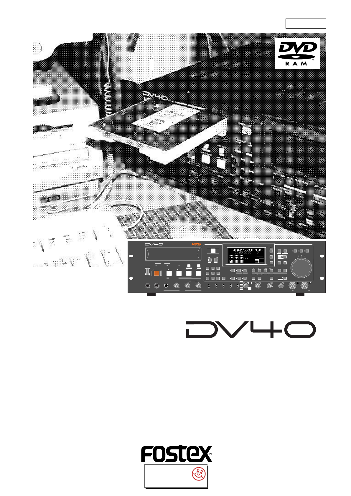
DVD Master Recorder
SHUTTLEJOGVARI PITCH
IN DSTOUT
symbol
SKIP/CURSOR
LOCATE
ENTER/YESEXIT/NO
DISP
MARGIN
FILE SEL
STORE
AUDIO EDIT UNDO
2
ABC
3
DEF
89
65
PQRS TUV WXYZ
GHI JKL MNO
TC RDY
INSLATETONEMUTE
INSERT
OPEN/CLOSE
07
4
1
RESET
TIME
LEVEL
MEMORYCUE POINT
SETUP
NEW FILE
INPUT MON
MUTE REC TONE REC
PREVIEW
HOLD
DIRECTORY
UTILITY
AUDIO RDY TR1
SOURCE OUT
space
BY-
PASS
ON
OFF
MINMAX MAX
BY-
PASS
ON
OFF
MIN
VIDEO
WORD
INT
24H RUN
REC RUN
FREE RUN
EXT RUN
TR1 INPUT LEVELTR2 TR4TR3CLOCK
30DF
29.97
29.97DF
25
24
23.97
30
RSVD
PULL
48
44.1
48
(kHz)
192
44.1
16BIT
88.2
96
176.4
-0.1%
NORM
+0.1%
MULTI(4TR)
STEREO
MONO
DIGITAL
ANALOG
SDII
BWF
REMOTE
LOCAL
TC GEN MODE
CONTROL UP/DOWN SAMPLING FREQ
TR MODE
INPUT
AUDIO FILE FRAME RATE
DVD MASTER RECORDER
MONO
MAXMIN
POWER
TR4
TR3
TR2
TR1,3+2,4
TR3+4
TR1+2 TR1
LOCATEREC END
LOCATEABS 0
F FWD
REWIND
PLAY
STOPRECORD
SOURCE PLAY
TC SETUP
LIST PLAYCHASE
EDIT
PHONES
HDDVD
DRIVE
KEYBOARD MOUSE
DIGITAL
TR2 TR3 TR4
SHIFT
DISP
HMSF
4
3
2
1
-INT-
BWF
FORMAT
CLOCK
-0.1%
kHz 4824
FS
BIT
PGM
ABS
∞
60 50 42 34 28 2018 12 86543210OL
+
-
TAPE MODE
24BIT
CLR
interstage
Phistersvej 31, 2900 Hellerup, Danmark
Telefon 3946 0000, fax 3946 0040
www.interstage.dk
-pro audio with a smile

2
CAUTION: TO REDUCE THE RISK OF ELECTRIC SHOCK,
DO NOT REMOVE COVER (OR BACK).
NO USER - SERVICEABLE PARTS INSIDE.
REFER SERVICING TO QUALIFIED SERVICE PERSONNEL.
CAUTION
RISK OF ELECTRIC SHOCK
DO NOT OPEN
9. Heat-Theappliance shouldbesituatedawayfrom heatsources
such as radiators, heat registers, stoves, or other appliances
(including amplifiers) that produce heat.
10. Power Sources- Theapplianceshouldbeconnectedtoa power
supply only of the type described in the operating instructions or
as marked on the appliance.
11. Grounding orPolarization- Theprecautionsthat shouldbetaken
so that the grounding or polarization means of an appliance is
not defeated.
12. Power Cord Protection - Power supply cords should be routed
so that they are not likely to be walked on or pinched by items
placeduponoragainstthem, payingparticular attentiontocords
at plugs, convenience receptacles, and the point where they
exit from the appliance.
13. Cleaning - The appliance should be cleaned only as
recommended by the manufacturer.
14. Nonuse Periods - The power cord of the appliance should be
unplugged from the outlet when left unused for a long period of
time.
15. Object and Liquid Entry - Care should be taken so that objects
do not fall and liquids are not spilled into the enclosure through
openings.
16. Damage Requiring Service - The appliance should be serviced
by qualified service personnel when:
A. The power supply cord or the plug has been damaged; or
B. Objects have fallen, or liquid has been spilled into the appliance; or
C. The appliance has been exposed to rain; or
D. The appliance does not appear to operate normally or
exhibits a marked change in performance; or
E. The appliance has been dropped, or the enclosure damaged.
17. Servicing - The user should not attempt to service the appliance
beyond that described in the operating instructions.
All other servicing should be referred to qualified service
personnel.
The lightning flash with arrowhead symbol, within an equilateral
triangle, is intended to alert the user to the presence of
uninsulated "dangerous voltage" within the product's enclosure
that may be of sufficient magnitude to constitute a risk of electric
shock to persons.
The exclamation point within an equilateral triangle is intended
to alert the user to the presence of important operating and
maintenance (servicing) instructions in the literature
accompanying the appliance.
CAUTION:
TO PREVENT ELECTRIC SHOCK, MATCH WIDE BLADE OF
PLUG TO WIDE SLOT, FULLY INSERT.
ATTENTION:
POUR EVITER LES CHOCS ELECTRIQUES, INTRODUIRE
LA LAME LA PLUS LARGE DE LA FICHE DANS LA BORNE
CORRESPONDANTE DE LA PRISE ET POUSSER JUSQU'
AU FOND.
An appliance and cart combination should be moved with care.
Quick stops, excessive force, and uneven surfaces may cause
the appliance and cart combination to overturn.
7. Wall or Ceiling Mounting - The appliance should be mounted to
a wall or ceiling only as recommended by the manufacturer.
8. Ventilation -The applianceshouldbe situatedsothat itslocation
or position dose not interfere with its proper ventilation.
For example, the appliance should not be situated on a bed,
sofa, rug, or similar surface that may block the ventilation
openings;or,placed inabuilt-in installation,such as abookcase
orcabinetthat may impedethe flow ofairthrough the ventilation
openings.
"WARNING"
"TO REDUCE THE RISK OF FIRE OR ELECTRIC SHOCK,
DO NOT EXPOSE THIS APPLIANCE TO RAIN OR
MOISTURE."
SAFETY INSTRUCTIONS
1. Read Instructions - All the safety and operating instructions
should be read before the appliance is operated.
2. Retain Instructions - The safety and operating instructions
should be retained for future reference.
3. Heed Warnings - All warnings on the appliance and in the
operating instructions should be adhered to.
4. Follow Instructions - All operating and use instructions should
be followed.
5. Water and Moisture - The appliance should not be used near
water - for example, near a bathtub, washbowl, kitchen sink,
laundry tub, in a wet basement, or near a swimming pool, and
the like.
6. Carts and Stands - The appliance should be used only with a
cart or stand that is recommended by the manufacturer.

3
Table of Contents
Chapter-1 Before using the DV40
Turning on the power............................................................................................1-2
Setting the internal clock.......................................................................................1-3
Loading a DVD-RAM disk.......................................................................................1-4
Formatting a DVD-RAM disk..................................................................................1-5
About audio files on a formatted disk...................................................................1-7
About REMAIN display............................................................................................1-8
Chapter-2 Names of Functions
Front panel part 1...................................................................................................2-3
Front panel part 2...................................................................................................2-6
FL display..................................................................................................................2-11
Front panel part 3..................................................................................................2-12
Rear panel.................................................................................................................2-14
Chapter-3 Reformatting/optimizing a DVD-RAM disk
Reformatting a DVD-RAM disk..............................................................................3-2
Optimizing a disk....................................................................................................3-5
Chapter-4 Recording/Playback the audio signal
About the expression for audio files in this manual............................................4-2
About the NEW FILE and INSERT mode.................................................................4-2
Recording an analog source in the NEW FILE mode.............................................4-3
Preparation......................................................................................................4-3
Preparation for recording.............................................................................4-4
Recording.........................................................................................................4-5
Playback of recorded audio...................................................................................4-6
Multiple-undo function...........................................................................................4-6
You can create an audio file before recording.....................................................4-7
Recording an analog source in the INSERT mode.................................................4-8
Preparation for recording.............................................................................4-8
Recording.........................................................................................................4-8
Selecting a desired file on a disk............................................................................4-9
Recording to a “Tape mode” audio file in the INSERT mode.............................4-10
Creating a “Normal mode” audio file on a disk formatted in the Tape mode.4-11
Recording a digital source in the NEW FILE mode.............................................4-12
Preparation......................................................................................................4-12
Preparation for recording.............................................................................4-13
Recording.........................................................................................................4-13
Recording a digital source in the INSERT mode.................................................4-14
Preparation for recording.............................................................................4-14
Recording.........................................................................................................4-14
MUTE recording.......................................................................................................4-15
Slate tone function..................................................................................................4-16
Cueing by the jog function...................................................................................4-17
Cueing/high speed shuttle by the shuttle function...........................................4-17

4
Chapter-5 Time code recording
Time code recording...............................................................................................5-2
Selecting the recording mode......................................................................5-2
Selecting source time code...........................................................................5-2
Recording time code generated by the internal time code generator................5-3
Settings of the DV40......................................................................................5-3
Recording external time code................................................................................5-4
Connection to external devices/Setting of the DV40.................................5-4
TC Setup mode details............................................................................................5-5
To enter the TC Setup mode.........................................................................5-5
Setting the internal TC generator start time...............................................5-6
Force-jamming to external time code..........................................................5-6
Selecting output time code...........................................................................5-7
Editing the chase offset.................................................................................5-7
Trimming the chase offset............................................................................5-8
Editing the LTC start time.............................................................................5-8
Catch offset.....................................................................................................5-9
Chase mode selection....................................................................................5-9
Chapter-6 Storing time data
Location memory keys............................................................................................6-2
Storing a time to an edit point memory................................................................6-3
Capturing a time “on the fly”.......................................................................6-3
Storing a time to an edit point using the numeric keys.............................6-4
Storing a time to locate memory (CUE/MEMORY)...............................................6-5
Storing a time to a locate point memory
(CUE or MEMORY point memory) “on the fly”..................................6-6
Storing a time to a locate point using the numeric keys............................6-7
Editing a name of CUE or MEMORY point.............................................................6-8
Clearing a CUE or MEMORY point memory...........................................................6-9
Chapter-7 Locate Function
A variety of locate functions..................................................................................7-2
Location to the beginning (ABS 0) of an audio file.....................................7-2
Location to the end (REC END) of the current audio file...........................7-2
Location to the last playback start position................................................7-3
Location to the last recording start position...............................................7-3
Location to the last recording end position................................................7-3
Location to the point where the recorder located last time......................7-4
Location to an audio file edit point..............................................................7-4
Location to a CUE point.................................................................................7-4
Location to a MEMORY point........................................................................7-5
Location to the next or previous
CUE/MEMORY point using the skip mode (Skip locate function)....7-5
Chapter-8 Preview Function
Preview at an edit point.........................................................................................8-2
Preview at a locate point........................................................................................8-3
Trimming while previewing audio........................................................................8-4

5
Chapter-9 Audio file management
Creating a new file..................................................................................................9-2
Creating a new file on a disk just after formatted in the Normal mode...9-2
Creating a new file on a disk just after formatted in the Tape mode.......9-3
Storing an audio file...............................................................................................9-4
Selecting a file using the file select function...............................................9-4
Selecting a file using the skip function........................................................9-4
Editing an audio file name.....................................................................................9-5
Deleting an audio file.............................................................................................9-6
Restoring a delete audio file..................................................................................9-7
Duplicating an audio file........................................................................................9-8
Converting the audio file format...........................................................................9-9
Dividing an audio file.............................................................................................9-10
Combining audio files.............................................................................................9-11
To combine into a STEREO file...................................................................9-11
To combine into a MULTI file.....................................................................9-12
Chapter-10 Editing track data
Pasting track data.................................................................................................10-2
Inserting track data..............................................................................................10-4
Erasing track data.................................................................................................10-6
Cutting track data.................................................................................................10-8
Chapter-11 Setup mode
How to access and set a Setup menu...................................................................11-2
Display contrast setting........................................................................................11-3
Reference level setting..........................................................................................11-3
Digital input track selection................................................................................11-3
Digital output signal format selection................................................................11-3
Skipped item selection for the skip mode..........................................................11-4
Auto EE mode On/Off...........................................................................................11-4
Self diagnoses On/Off...........................................................................................11-4
Panel lock On/Off..................................................................................................11-5
Peak hold time setting..........................................................................................11-5
GPI On/Off..............................................................................................................11-5
Slate tone recording time.....................................................................................11-6
Mute recording time.............................................................................................11-6
Save/load of setup data.......................................................................................11-6
Saving setup data.........................................................................................11-6
Loading setup data......................................................................................11-7
TCP/IP settings.......................................................................................................11-8
Showing the IP address...............................................................................11-8
Setting the IP address..................................................................................11-8
Showing the router IP address...................................................................11-9
Setting the router IP address......................................................................11-9
Showing the subnet mask...........................................................................11-9
Setting the subnet mask.............................................................................11-9
Setting the log-in names and passwords.................................................11-10
Showing the MAC address..........................................................................11-10

6
Showing the main software version...................................................................11-11
Showing the ethernet software version.............................................................11-11
Showing the running time...................................................................................11-11
Chapter-12 Preview Function
How to select a Utility menu................................................................................12-2
Selecting Rec Protect On or Off............................................................................12-3
Renumbering CUE points.....................................................................................12-3
Releasing undo files..............................................................................................12-4
Selecting On or Off of the resume function........................................................12-4
Chapter-13 Importing an audio file to a computer
Chapter-14 Specifications
1-1
Chapter-1
Before using the DV40
Before using the DV40, you must carry out some preparations. This chap-
ter describes how to set the internal clock and how to format a DVD-RAM
disk.
1-2
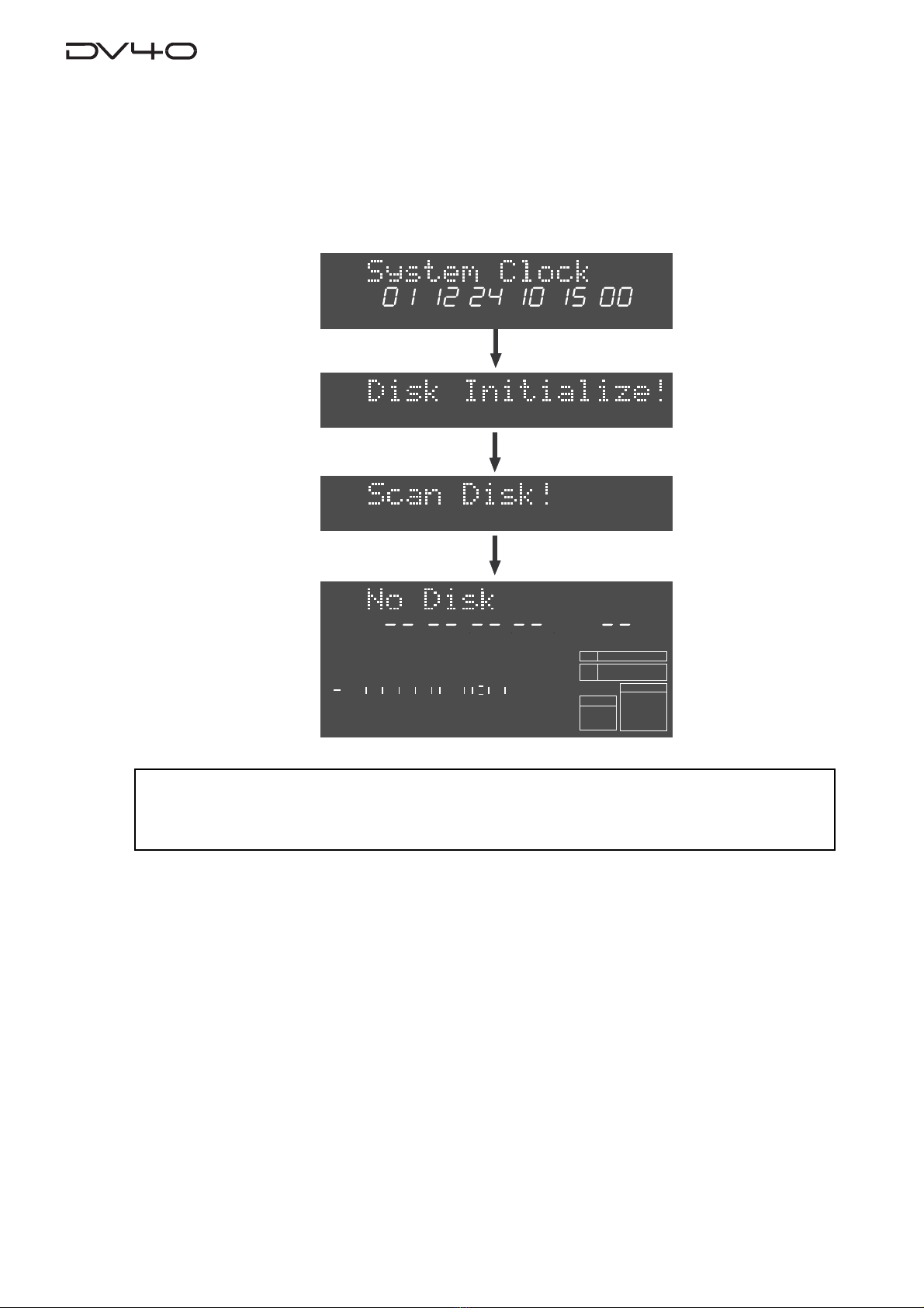
Turning on the power
After connecting the supplied power cord, you can turn on the power of the unit.
1. Press down the [POWER] switch.
After showing the start-up display (showing the system clock, followed by "Disk Initialize!"), the unit
activates and scans the disk (showing "Scan Disk!"), then shows "No Disk".
<Note>
When turning off the power, make sure that the unit is not in the Setup mode and ceases disk
access.
YMDHM S
DATE
HMSF
4
3
2
1
-INT-
BWF
FORMAT
CLOCK
kHz 4824
FS
BIT
PGM
ABS
∞
60 50 42 34 28 2018 12 86543210OL
1-3
Setting the internal clock
The internal clock is built in the unit, which is adjusted to the Japanese time when shipped.
Set the clock to your local time before using according to the following procedure. The clock time
information is used for tentative names when creating audio files and necessary data when execut-
ing the multiple undo function.
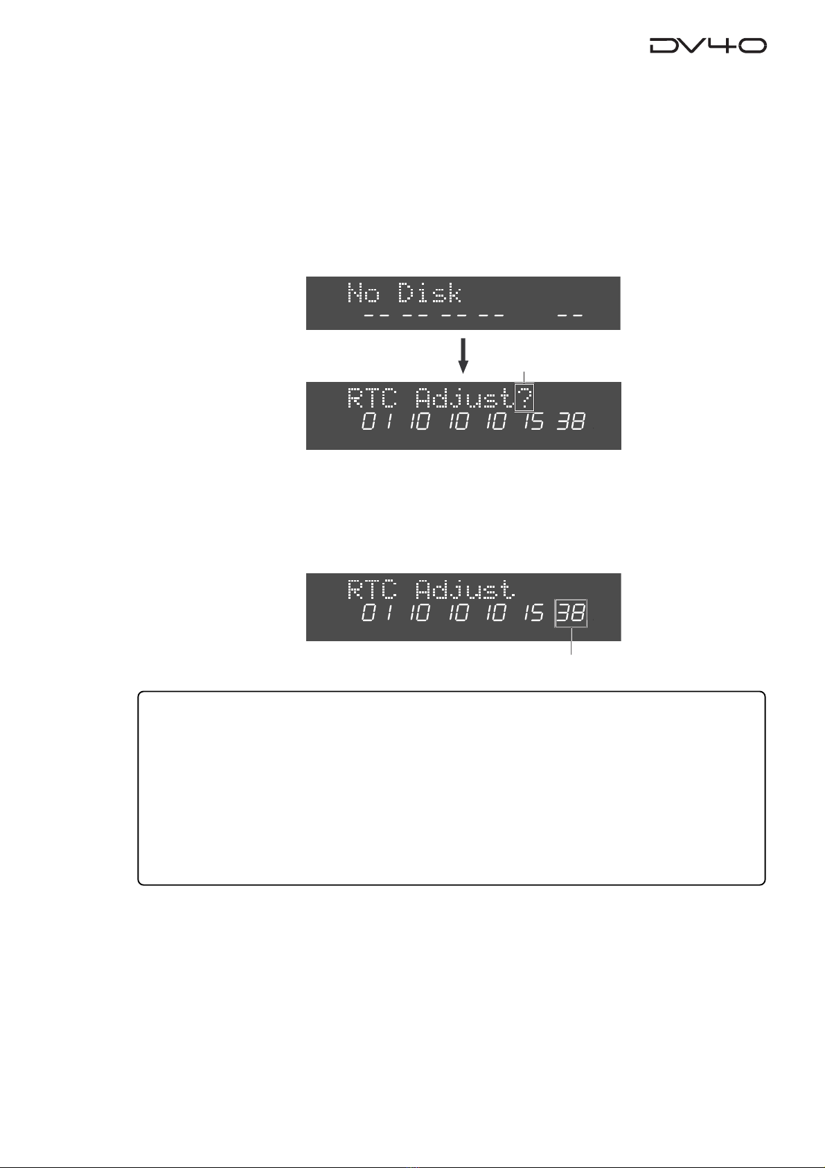
1.Press the [SETUP] key.
The display changes to the "RTC Adjust?", one of menu items in the Setup mode, from "No Disk".
The current internal clock time is shown.
HMSF
ABS
YMDHM S
SETUP
2.Press the [ENTER/YES] key.
"?" disappears while the number in the "second" digit starts flashing, showing that the date/time
value now can be edited.
Set the date/time value appropriately according to the following methods.
• Use the [SKIP/CURSOR] I<</>>I keys to move the editing point, and use the jog dial to enter
the value.
or
• Use the numeric keys to enter the date/time value directly.
When entering data using the numeric keys, regardless of the current editing point, the value is
entered from the right-hand (second) digit which moves left as additional digits are entered.
For example, to set the clock to 3:10:00 p.m. of December 1. 2001, press the numeric keys in the
following order.
0 -> 1 -> 1 -> 2 -> 0 -> 1 -> 1 -> 5 -> 1 -> 0 -> 0 -> 0
YMDHM S
SETUP
Flashing
3.Press the [ENTER/YES] key after enter the value.
The internal clock starts from the entered date/time value.
You can precisely set the clock by listening to the time signal when pressing the [ENTER/YES] key.
4.Press the [EXIT/NO] key.
The unit exits the Setup mode and the display shows "No Disk" again.
Flashing
1-4
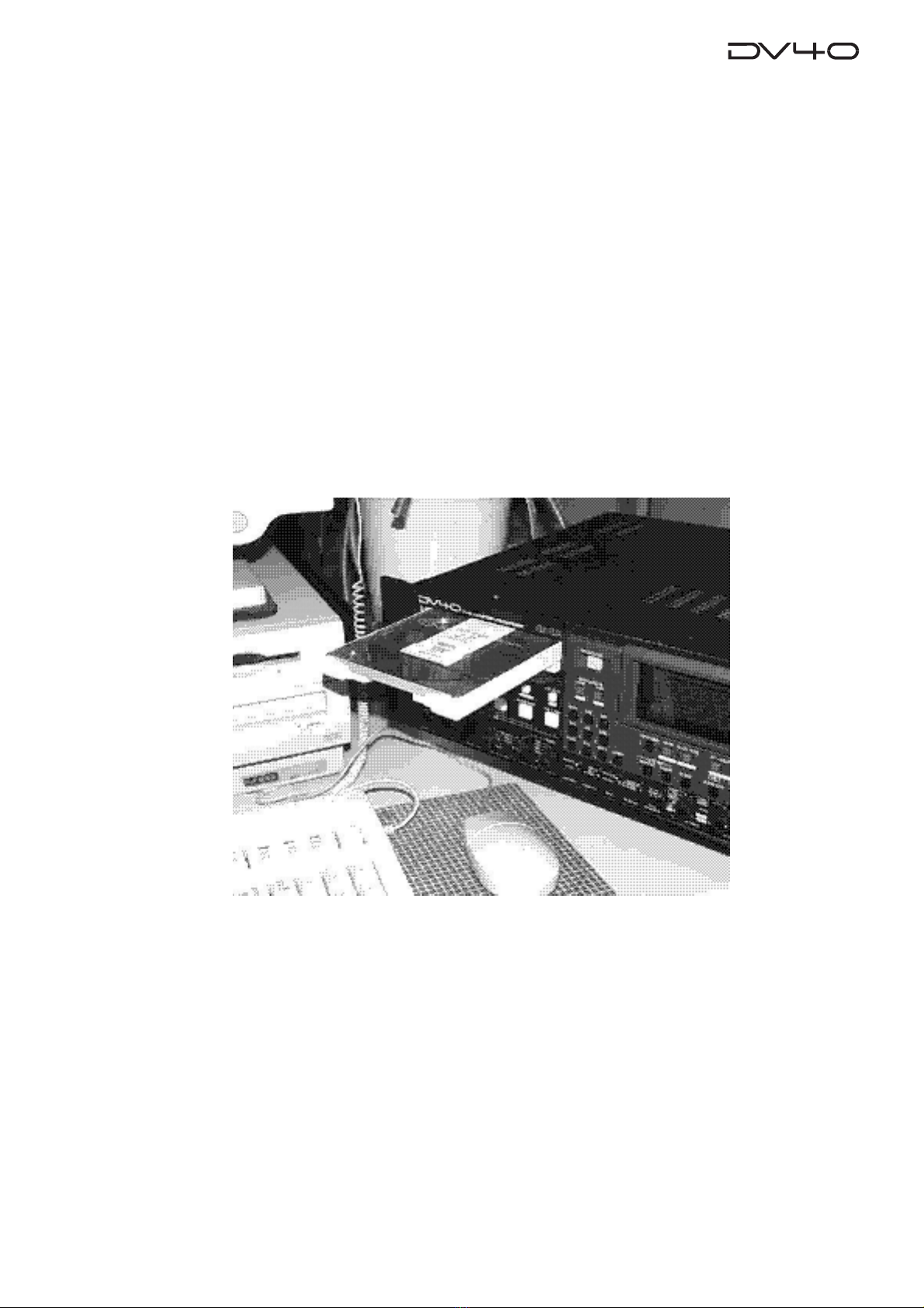
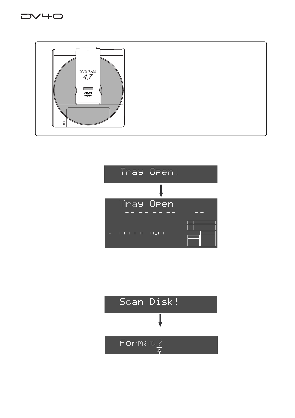
Loading a DVD-RAM disk
1.Press the [OPEN/CLOSE] key.
The display shows "Tray Open!" and the tray opens.
2.Place a DVD-RAM disk in the tray, and press the [OPEN/CLOSE] key again (or push
the front of the tray lightly).
The disk is loaded. After the unit scans the disk ("Disk Scan!" is shown as a flashing display while
scanning), it automatically recognizes that the disk is unformatted and enters the "Format" menu
("Format" with flashing "?" is shown).
You can format the disk by the following procedure in the next page.
REWRITABLE
About usable DVD-RAM disks
TYPE 2, one-side disks with 4.7 GB capacity can be used
with the DV40.
Flashing
HMSF
4
3
2
1
-INT-
BWF
FORMAT
CLOCK
kHz 4824
FS
BIT
PGM
ABS
∞60 50 42 34 28 2018 12 86543210OL
1-5
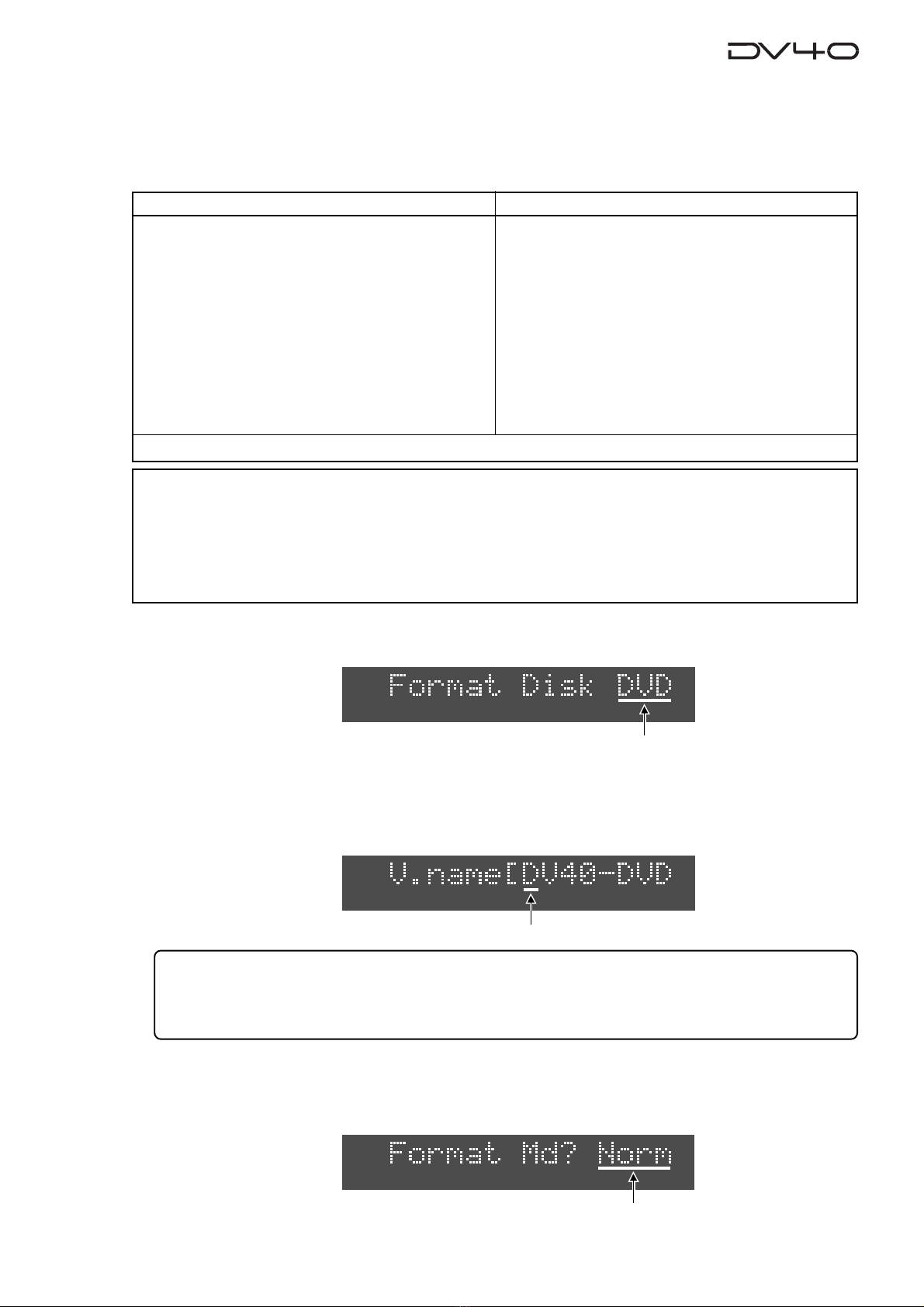
Formatting a DVD-RAM disk
To make a DVD-RAM disk usable with the DV40, format the disk by the “UDF format”.
Two format modes, “Normal” and “Tape”, are available with this unit. Use either format according to
the situation.
1.While "Format" with flashing "?" is shown on the display,press the [ENTER/YES] key.
The display changes to show "Format Disk DVD" (in which "DVD" is flashing).
Tips: How to enter a desired volume name
Press the [MARGIN RESET/CLR] key repeatedly until the tentative name currently shown is erased.
By using the jog dial (or using the appropriate numeric key), you can enter the desired character at the
editing point (flashing point). You can move the editing point by pressing [SKIP/CURSOR] I<</>>I key.
2.Press the [ENTER/YES] key again.
The display changes to show "V.name [DV40-DVD" (in which "D" of "DV40" is flashing).
This shows the volume name of the disk can be edited and "DV40-DVD" is the tentative name.
See the following Tips for details about how to enter a desired volume name. Of course, you may use
the tentative name.
3.After entering a volume name, press the [ENTER/YES] key.
The display changes to show "Format Md?" with flashing "Norm".
You can select the format mode between "Norm" (Normal) and "Tape" using the jog dial.
Normal Mode Tape Mode
Normally, format a disk by selecting the format mode
to Normal.
No audio file is automatically created when formatting
the disk in the Normal mode ("No Audio Files!" is shown
after formatting is completed).
On a "Normal format" disk, a "Normal mode" audio
file ("BWF" or "SDII") is automatically created when
executing recording in the NEW FILE mode.
Or you can also create "Normal mode" audio files us-
ing the file select function before recording. Up to 200
audio files can be created.
Two “Tape mode” audio files (“BWF” or “SDII”) of ap-
proximately 2 GB each are automatically created on a
disk when formatting the disk in the Tape mode.
Like an analog tape, a “Tape mode” audio file has the
fixed available space, and can playback recorded data
even if the system unexpectedly shuts down during
recording and the system data is destroyed. There-
fore, a “Tape mode” audio file is suitable for live re-
cording or preserving recorded data for a long period
of time.
You can also create “Normal mode” audio files in the
remaining space (approximately 0.7 GB) on a disk for-
matted in the Tape mode.
<Notes for formatting a disk in theTape mode>
When a disk is formatted in the Tape mode, an audio file is automatically created. Therefore, before formatting,
you must set the AUDIO FILE, TR MODE and SAMPLING FREQ switches on the front panel appropriately. Note that
you cannot change the settings after formatting.)
When formatting a disk in the Normal mode, you do not need to set these switches. however, you must set them
appropriately when making recording in the NEW FILE mode or creating a new audio file using the file select
function.
* See "About audio files on a formatted disk" on page 1-7 for details about audio files.
Flashing
Flashing
Flashing
1-6
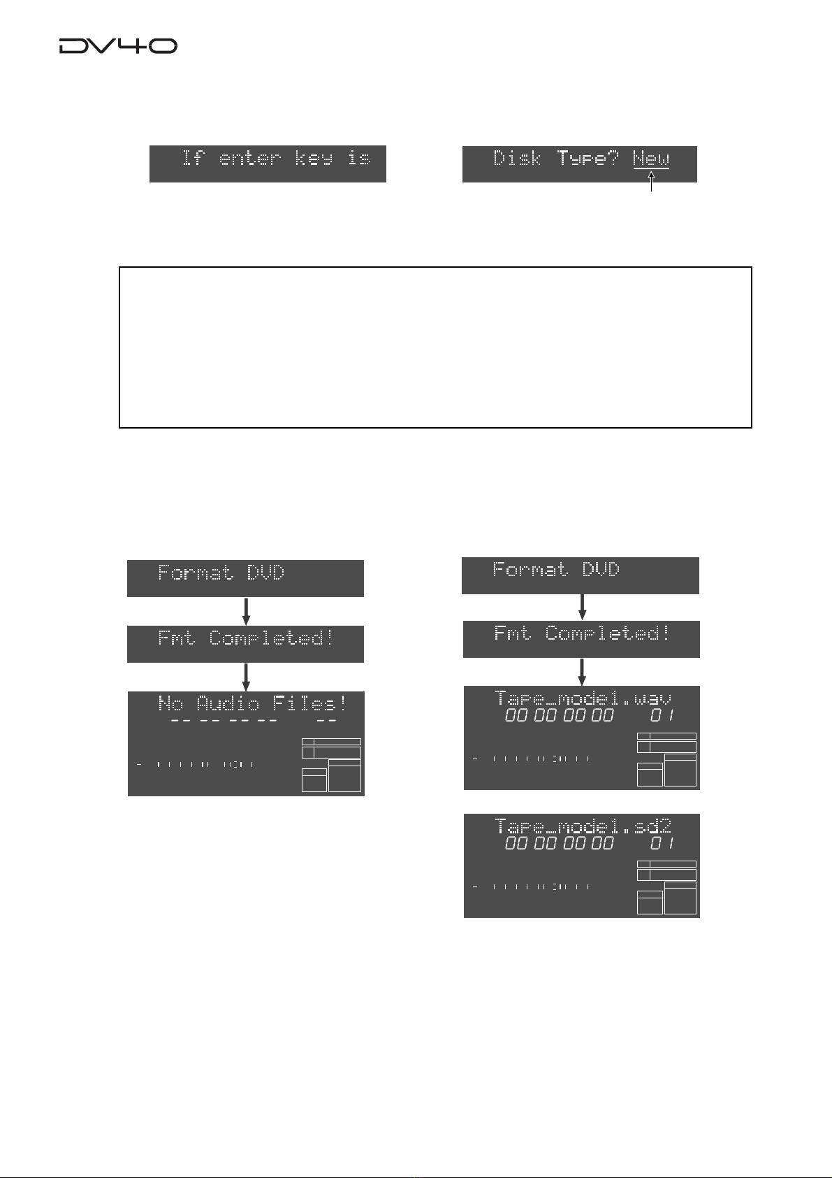
4.Select the format mode and press the [ENTER/YES] key.
If you select "Norm", the display shows "If enter key is pushed, will start formatting and delete DVD area data.
Are you sure?". If you are sure, proceed to the next step.
5.Press the [ENTER/YES] key.
If you set the disk type to "New", regardless of the format mode ("Norm" or "Tape"), the formatting
is completed quickly and "Fmt Completed!" is shown, followed by the screens as below depending on
the formatting mode.
HMSF
4
3
2
1
-INT-
BWF
FORMAT
CLOCK
kHz 4824
FS
BIT
PGM
ABS
∞
60 50 42 34 28 2018 12 86543210OL
If you select "Tape", the display shows "DiskType?" with flashing "New" for selecting disk type.
Select "New" or "Used" using the jog dial, and then go to the next step.
Formatting a disk in the Normal mode Formatting a disk in theTape mode with "DiskType" set to "New"
After completing formatting a disk in the Nor-
mal mode, "No Audio Files!" appears, showing
that there is no audio file on the disk.
or
After completing formatting, a single "Tape mode" audio
file is created, with appropriate audio file format, TR mode
and sampling frequency according to the settings of the
[AUDIO FILE], [TR MODE] and [SAMPLING FREQ] switches.
Also, the “TAPE MODE” indicator (red) on the front panel
is lit.
<Note>
• When formatting a used disk in the Tape mode, select
"Used"
. If you select
"New"
, the existing
data may not be erased, with the result that a recording error may occur when a new recording
is made.
• If you format a disk in the Tape mode with "Disk Type" set to
"used"
, it takes some time for
formatting. The display counts down the unformatted area.
Because each of two
“Tape mode”
audio file reserves approximately 2 GB of recording space,
the count-down of REMAIN starts from approximately 4 GB.
Flashing
HMSF
2
1
-INT-
BWF
FORMAT
CLOCK
-0.1%
kHz 4824
FS
BIT
PGM
ABS
∞
60 50 42 34 28 2018 12 86543210OL
HMSF
2
1
-INT-
SDII
FORMAT
CLOCK
-0.1%
kHz 4824
FS
BIT
PGM
ABS
∞
60 50 42 34 28 2018 12 86543210OL

1-7
About audio files on a formatted disk
As described earlier, two format modes, Normal and Tape, are available with this unit, and in result, there are
two audio file types; "Normal mode" file and "Tape mode" file.
In short, a "Normal mode" file is a typical disk recorder file that can be edited comprehensively, while a "Tape
mode" file is more straightforward and you may regard it as a tape-like file.
The following describes detail information about disks formatted in Normal and Tape modes.
•A disk formatted in the "Normal" format mode
No audio file is created on the disk when formatted. A "Normal mode" audio file is created automatically
when performing recording in the NEW FILE mode. You can also create "Normal mode" audio files
manually using the file select function. Up to 99 audio files can be created. Two directories, “bwff” for
BWF (Broadcast Wave Format) and “sd2f” for SDII (Sound Designer II) files, may be created and managed
on a disk.
•A disk formatted in the "Tape" format mode
Two “Tape mode” audio files (“BWF” or “SDII”) of approximately 2 GB each created on a disk formatted in
the “Tape” format mode. The file format of the “Tape mode” files is determined by the [AUDIO FILE] switch
setting when formatted.
The two “Tape mode” audio files are more tape-like, so you may regard as if there were two analog tapes
on a disk. If an accident, such as a sudden power failure or shutdown of the unit, may happens during
recording, data on a “Tape mode” audio file recorded before the accident will survive (while, in the same
situation, data on a “Normal mode” audio file will be all lost).
Note that, though you cannot create more than two “Tape mode” audio files on a disk formatted in the
“Tape” mode, you can create one or more “Normal mode” audio files (“BWF” or “SDII”).
Each “Normal mode” audio file is also stored in the appropriate directory (“bwff” or “sd2f”).
Disk just after formatted
Disk just after formatted
“No Audio Files!”
See "Chapter 4: Audio recording/playback" and "Chapter 9: Editing an audio file" for details about how to
create an audio file.
bwff
*************.wav (01)
*************.wav (02)
*************.wav (03)
*************.wav (04)
*************.wav (05)
sd2f
*************.sd2 (01)
*************.sd2 (02)
*************.sd2 (03)
*************.sd2 (04)
*************.sd2 (05)
bwff
Tape_mode.wav (01)
Tape_mode.wav (02)
*************.wav (03)
*************.wav (04)
*************.wav (05)
sd2f
*************.sd2 (01)
*************.sd2 (02)
*************.sd2 (03)
*************.sd2 (04)
*************.sd2 (05)
bwff
************.wav (01)
************.wav (02)
************.wav (03)
************.wav (04)
************.wav (05)
sd2f
Tape_mode.sd2 (01)
Tape_mode.sd2 (02)
*************.sd2 (03)
*************.sd2 (04)
*************.sd2 (05)
bwff
or
sd2f
Tape Mode
File-1 Tape Mode
File-2

1-8
About REMAIN display
You can check the remaining (recordable) time/space by selecting the appropriate display using the [DISP
TIME] key. The unit can show the remaining time and space that can be used for "Normal mode" files, regard-
less of whether the disk is formatted in the "Normal" or "Tape" mode.
• If a disk is formatted in the Normal mode
1.While a disk is stopped and the display shows "No Audio FIles!", press the [DISP
TIME] key three times.
The display shows the "FreeArea" screen, in which the recordable space (in MB) and time (in hours/minutes/
seconds) for files with the current [TRACK MODE] and [SAMPLING FREQ] switch settings are shown.
The screen example on the right below shows the recordable time and space when the disk is formatted with the
[TR MODE] and [SAMPLING FREQ] switch settings to "MONO" and "44.1 kHz/24 bit" respectively.
2.Press the [TR MODE] and [SAMPLING FREQ] switches as desired.
By changing the [TRACK MODE] and [SAMPLING FREQ] switch settings, you can check the recordable space and
time according to the current switch settings.
The screen examples below shows the values in two cases when the [TR MODE] switch is set to "STEREO" and
"MULTI (4TR)" while the [SAMPLING FREQ] switch is fixed to "44.1 kHz/24 bit".
TR MODE -> "STEREO" TR MODE -> "MULTI (4TR)"
HMSF
1
24BIT
PGM
ABS
HMS
1
24
BIT
MB
REMAIN
HMS
BIT
MB
REMAIN
HMS
1
24
BIT
MB
REMAIN
<Tips>
The recordable space of each “Tape mode” file is fixed to approximately 2.0 GB, which is not included in the Free
Area, as shown above. You can see the maximum recordable time of the “Tape mode” audio file by following the
operation below.
* While a disk is stopped, press the [F FWD] key while holding down the [STOP] key.
The current position moves to the end of the “tape”, and the maximum recordable time of a “Tape mode” file, with
the track mode and sampling frequency/bit length selected by the [TR MODE] and [SAMPLING FREQ] switches
when formatted, is shown on the display. The example on the right below shows that the maximum recordable
time in mono is approximately 3 hours 53 minutes. You can calculate the remaining time of a “tape mode” file by
subtracting the elapsed time from the maximum recordable time.
• If a disk is formatted in theTape mode
1.While the "Tape mode" audio file is selected, press the [DISPTIME] key three times.
The display shows the “FreeArea” screen, as with a disk formatted in the Normal mode. In this screen, the recordable
space (in MB) and time (in hours/minutes/seconds) for “Normal mode” files, with the same track mode and sampling
frequency/bit length settings as when the disk is formatted, are shown. In other words, the recordable space shown
here is the value calculated by subtracting 4.0 GB from all recordable space of the disk.
The screen example on the right below shows the values when the disk is formatted by setting the [TR MODE] and
[SAMPLING FREQ] switches to “MONO” and “48kHz/24bit” respectively.
The recording time in mono is 47 minutes 30 seconds, while the available space is 0.4 GB.
Note that, with a disk formatted in the Tape mode, if you change the settings of the [TR MODE] and [SAMPLING FREQ]
switches, the values on the display may not be changed.
HMSF
1
24
BIT
PGM
ABS
HMSF
1
24
BIT
PGM
ABS
HMSF
1
24
BIT
PGM
ABS
HMS
1
24
BIT
MB
REMAIN
2-1
Chapter-2
Names and Functions
This chapter describes names and functions of controls on the front panel, as well as
those of connectors on the rear panel.
2-2
SHUTTLEJOGVARI PITCH
IN DSTOUT
symbol
SKIP/CURSOR
LOCATE
ENTER/YESEXIT/NO
DISP
MARGIN
FILE SEL
STORE
AUDIO EDIT UNDO
2
ABC
3
DEF
89
65
PQRS TUV WXYZ
GHI JKL MNO
TC RDY
INSLATE TONEMUTE
INSERT
OPEN/CLOSE
07
4
1
RESET
TIME
LEVEL
MEMORYCUE POINT
SETUP
NEW FILE
INPUT MON
MUTE REC TONE REC
PREVIEW
HOLD
DIRECTORY
UTILITY
AUDIO RDY TR1
SOURCE OUT
space
BY-
PASS
ON
OFF
MINMAX MAX
BY-
PASS
ON
OFF
MIN
VIDEO
WORD
INT
24H RUN
REC RUN
FREE RUN
EXT RUN
TR1 INPUT LEVELTR2 TR4TR3CLOCK
30DF
29.97
29.97DF
25
24
23.97
30
RSVD
PULL
48
44.1
48
(kHz)
192
44.1
16BIT
88.2
96
176.4
-0.1%
NORM
+0.1%
MULTI(4TR)
STEREO
MONO
DIGITAL
ANALOG
SDII
BWF
REMOTE
LOCAL
TC GEN MODE
CONTROL UP/DOWN SAMPLING FREQ
TR MODE
INPUT
AUDIO FILE FRAME RATE
DVD MASTER RECORDER
MONO
MAXMIN
POWER
TR4
TR3
TR2
TR1,3+2,4
TR3+4
TR1+2 TR1
LOCATE REC END
LOCATE ABS 0
F FWD
REWIND
PLAY
STOPRECORD
SOURCE PLAY
TC SETUP
LIST PLAYCHASE
EDIT
PHONES
HDDVD
DRIVE
KEYBOARD MOUSE
DIGITAL
TR2 TR3 TR4
SHIFT
DISP
H
YM
MS
D
F
H
SF
MS
dB
%
4
3
2
1
DIGITAL
VIDEO
WORD
-EXT-
-INT-
DVD
BWF
SDII
FORMAT
CLOCK
-0.1%
kHz 44.1 88.2 176.4
192
DSD
96
32
4824
32 2016
FS
BIT
LEVELMARGINNEXTMBPGM
CHASERDYTCDIGITAL
CHASEOFFSET
UB
GENMEMORY
ABSCUE
LOCATE
REMAIN
DATEINLTC
SETUP
∞
60 50 42 34 28 2018 12 86543210OL
+
-
TAPE MODE
24BIT
+4dBu
-10dBV +4dBu
-10dBV
+4dBu
-10dBV +4dBu
-10dBV
TR4 TR2
TR3 TR1 TR3 TR1BAL [+4dBu] BAL [+4dBu]
UNBAL
[-10dBV]
UNBAL
[-10dBV]
TR4 TR2
BAL [+4dBu] BAL [+4dBu]
UNBAL
[-10dBV]
UNBAL
[-10dBV]
OUTPUT
THRU
INPUT
10/100
LINK
TX/RX
TR4-3 TR2-1
TR2 TR1
TR1
TR2
1:GND
2:HOT
3:COLD
192kHz
176.4kHz
INPUT OUTPUT
INPUT
75Ω
ON OFF
INPUT
75Ω
ON OFF
TR4-3 TR2-1
TR2 TR1
THRU
THRU OUTPUT
AC IN
1: GND 2: HOT 3: COLD 1: GND 2: HOT 3: COLD
1: GND
2: HOT
3: COLD
15P-REMOTE 9P-REMOTE
GPI
DIGITAL OUTPUT WORD
TIME CODE ETHERNET
ANALOG INPUT BALANCED ANALOG OUTPUT DIGITAL INPUT VIDEO
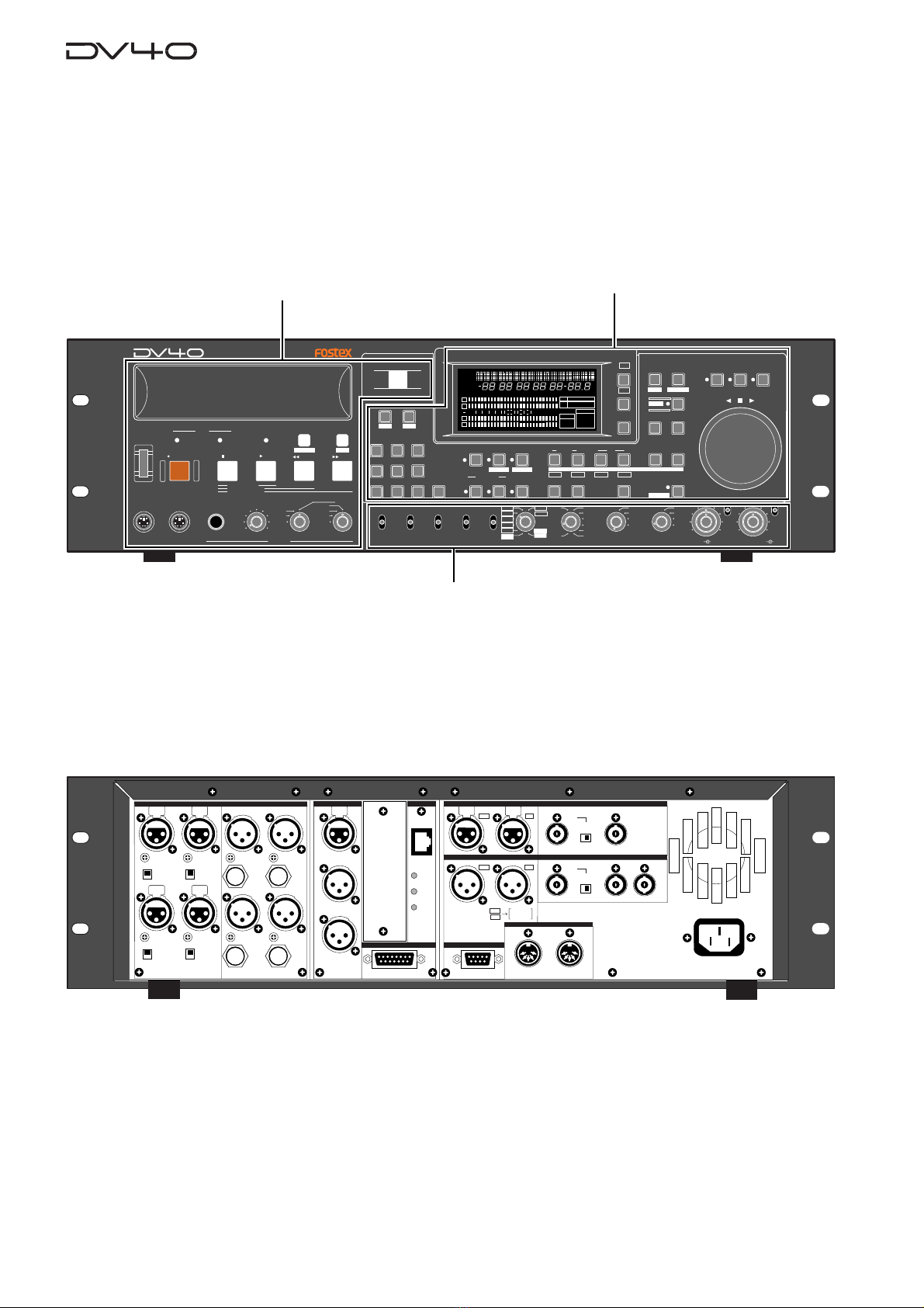
Front panel
We divide the front panel into three parts and describe names and functions of controls for each section.
*Some keys have the secondary function which is available when the SHIFT indicator is lit, while the primary
function is available when the SHIFT indicator is unlit. In this manual, we sometimes say "when shifted" and
"when unshifted" instead of "when the SHIFT indicator is lit" and "when the SHIFT indicator is unlit" respec-
tively.
Rear panel
Front panel part 1 Front panel part 2
Front panel part 3

2-3
Front panel part 1
SKIP/CURSOR
2
ABC
3
DEF
89
65
PQRS TUV WXYZ
GHI JKL MNO
OPEN/CLOSE
07
4
1
space
DIGITAL
ANALOG
SDII
BWF
REMOTE
LOCAL
CONTROL INPUT
AUDIO FILE
DVD MASTER RECORDER
MONO
MAXMIN
POWER
TR4
TR3
TR2
TR1,3+2,4
TR3+4
TR1+2 TR1
LOCATE REC END
LOCATE ABS 0
F FWD
REWIND
PLAY
STOPRECORD
SOURCE PLAY
TC SETUP
LIST PLAYCHASE
EDIT
PHONES
HDDVD
DRIVE
KEYBOARD MOUSE
+
-
TAPE MODE
2
3456 7
9
1011
1
8
POWER
HDDVD
DRIVE
1. [POWER] switch
Turns on or off the power of the unit.
2. Disk tray
Loads a DVD-RAM disk. Use the [OPEN/CLOSE] key to open or close the tray.
3. [DRIVE (DVD/HD)] indicators
The indicator for the current (currently selected) drive is lit.
In the initial condition, the "DVD" drive is selected. If the optional HD drive is in-
stalled, you can select the "HD" drive using the "Drive Sel?" menu in the Utility mode.
See "Chapter12: Utility mode" for details.
4. [TAPE MODE] indicator
It is lit when a "TAPE mode" audio file is loaded.
See "Chapter 1: Before using the DV40" for details about the format mode.
5. [CHASE] ([TC SETUP]) key
This key has primary (unSHIFTed) and secondary (SHIFTed) functions.
When unSHIFTed:
Turns on or off the chase mode.
When on, "CHASE" flashes in red on the display, which lights steadily when the unit
chase-locked to the external device.
When SHIFTed:
Enters the TC (Timecode) setup mode, in which you can make settings for recording/
playback of timecode.
See "Chapter 6: Recording/playback of timecode" for details.
TC SETUP
CHASE
2-4
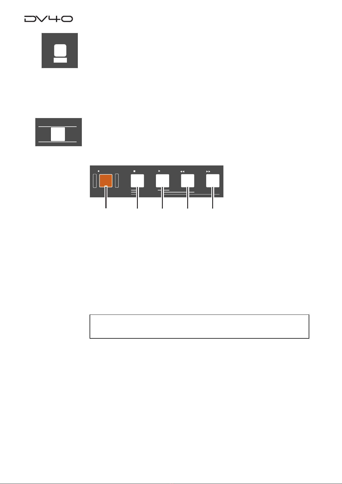
a. [RECORD] key
Normally, pressing this key starts recording when one of the AUDIO RDY indicators
([NEW FILE] or [INSERT]) is lit.
• In the NEW FILE mode:
Starts recording to a new file which is automatically created. If the "TC RDY" indicator
is lit, timecode is also recorded.
• In the INSERT mode:
Starts recording from the current position of the current file. If the "TC RDY" indica-
tor is lit, timecode is also recorded.
See "Chapter 4:Audio recording/playback" and "Chapter 5:Timecode recording" for details.
<Note>
If you press the
[RECORD]
key when the
"REC PROTECT"
setting in the Utility mode is set to
"On"
,
"Protected!"
is shown and you cannot start recording.
8.Transport keys
b. [STOP] key
Normally, pressing this key stops the recorder.
In the Setup, Utility and all sort of editing mode, pressing this key exits the current
mode.
Also, pressing the [PLAY], [<<REWIND] or [>>F FWD] key while holding down this key
executes the following.
• [STOP] + [PLAY]
Plays back sound data on the clipboard and stops the recorder.
• [STOP] + [<<REWIND]
Locates to ABS0 and stops the recorder.
• [STOP] + [>>F FWD]
Locates to REC END and stops the recorder.
LOCATE REC END
LOCATE ABS 0
F FWD
REWIND
PLAY
STOPRECORD
SOURCE PLAY
abcde
6. [LIST PLAY] ([EDIT]) key
This key has primary (unSHIFTed) and secondary (SHIFTed) functions.
When unSHIFTed:
When a play list is recorded in the BMF file, pressing this key starts playback accord-
ing to the play list.
(Note that this function is not available with an SDII file.)
When SHIFTed:
Pressing this key enables editing of the recorded play list.
See "Executing a play list/Editing a play list" on page XX for details.
LIST PLAY
EDIT
OPEN/CLOSE
7. [OPEN/CLOSE] key
Opens or closes the disk tray.

2-5
c. [PLAY] key
Normally, pressing this key starts playback.
Pressing this key during recording stores cross fade data to the memory and stops.
If any sound data is available on the clipboard, pressing this key while holding down
the [STOP] key plays back the sound data.
d. [|<<REWIND] key
Pressing this key while stopped rewinds the recorder at maximum 30 x speed.
Pressing this key during playback rewinds with sound (cues backwards) at 2 x speed.
Pressing this key while holding down the [STOP] key locates the "REC END" position
(the last recording position).
e. [>>| F FWD] key
Pressing this key while stopped fast-forwards the recorder at maximum 30 x speed.
Pressing this key during playback fast-forwards with sound (cues forwards) at 2 x
speed.
Pressing this key while holding down the [STOP] key locates the "ABS 0" position (the
beginning position of the file).
9. Monitor section
a. PHONES jack
Connects headphones for monitoring.
b. Headphones level control
Adjust the level of headphones.
c. Monitor track selection switch
Selects tracks to be monitored from among "3+2, 4", "3+4" or "1+2"", or selects
MONO. When selecting MONO, you can select any mono track by using the Mono
track select switch.
d. Mono track select switch
Selects a track to be monitored from among tracks 1 through 4 when the Monitor
track selection switch is set to MONO.
10. [MOUSE] connector
Connecting a mouse to this connector allows you to control the unit.
See "Chapter 13: Advanced functions" for details.
MONO
MAXMIN
TR4
TR3
TR2
TR1,3+2,4
TR3+4
TR1+2 TR1
PHONES
MOUSE
11. [KEYBOARD] connector
Connecting a computer keyboard to this connector allows you to control the unit.
See "Chapter 13: Advanced functions" for details.
KEYBOARD

2-6
Front panel part 2
12. [SKIP/CURSOR |<<, >>|] ([-], [+]) keys
This key has primary (unSHIFTed) and secondary (SHIFTed) functions.
When unSHIFTed:
• Skips to the next (>>|) or previous (|<<) "ABS 0" of an audio file, cue point or MEM
point, depending on the setting of the "Skip Mode?" menu in the Setup mode.
In the initial setting, "File" is selected, so each press of the key skips to the next or
previous "ABS 0" of an audio file.
• In a character entering mode in which you have to move the cursor to a position to
be edited, pressing the key moves the cursor.
• While executing the list play, pressing the key moves to the next (>>|) or previous
(|<<) CUE point.
When SHIFTed:
• Enters the plus or minus sign while editing a time value.
13. FL display
Displays time information, track levels and other setting items, etc.
14. [MARGIN RESET/CLR] key
When the margin level is shown on the display, pressing this key resets the margin
level.
When editing a file name, pressing this key clears the character in the current cursor
position.
SHUTTLEJOGVARI PITCH
IN DSTOUT
symbol
SKIP/CURSOR
LOCATE
ENTER/YESEXIT/NO
DISP
MARGIN
FILE SEL
STORE
AUDIO EDIT UNDO
2
ABC
3
DEF
89
65
PQRS TUV WXYZ
GHI JKL MNO
TC RDY
INSLATE TONEMUTE
INSERT
OPEN/CLOSE
07
4
1
RESET
TIME
LEVEL
MEMORYCUE POINT
SETUP
NEW FILE
INPUT MON
MUTE REC TONE REC
PREVIEW
HOLD
DIRECTORY
UTILITY
AUDIO RDY TR1
SOURCE OUT
space
BY-
PASS
ON
OFF
MINMAX MAX
BY-
PASS
ON
OFF
MIN
VIDEO
WORD
INT
24H RUN
REC RUN
FREE RUN
EXT RUN
TR1 INPUT LEVELTR2 TR4TR3CLOCK
30DF
29.97
29.97DF
25
24
23.97
30
RSVD
PULL
48
44.1
48
(kHz)
192
44.1
16BIT
88.2
96
176.4
-0.1%
NORM
+0.1%
MULTI(4TR)
STEREO
MONO
DIGITAL
ANALOG
SDII
BWF
REMOTE
LOCAL
TC GEN MODE
CONTROL UP/DOWN SAMPLING FREQ
TR MODE
INPUT
AUDIO FILE FRAME RATE
DIGITAL
TR2 TR3 TR4
SHIFT
DISP
H
YM
MS
D
F
H
SF
MS
dB
%
4
3
2
1
DIGITAL
VIDEO
WORD
-EXT-
-INT-
DVD
BWF
SDII
FORMAT
CLOCK
-0.1%
kHz 44.1 88.2 176.4
192
DSD
96
32
4824
32 2016
FS
BIT
LEVELMARGINNEXTMBPGM
CHASERDYTCDIGITAL
CHASEOFFSET
UB
GENMEMORY
ABSCUE
LOCATE
REMAIN
DATEINLTC
SETUP
∞
60 50 42 34 28 2018 12 86543210OL
+
-
24BIT
15
12 13 14 16 17 181920 21 22
23
24
25
26
27
28
29
30
31
32
33
34
35
36
37
38
39
40
41
42
SKIP/CURSOR
+
-
MARGIN
RESET
Other manuals for DV-40
10
Table of contents
Other Fostex DVD Recorder manuals


